With the torque tube mated to the transaxle, I could move forward on my shift linkage. Many of these steps could have been performed earlier, but I chose to wait until I could get everything set up and adjusted before starting this part of the project. If you're planning to work on your shift linkage with the drivetrain in the car, this writeup isn't going to help you much except maybe to illustrate how everything fits together and maybe highlight some potential issues before you get under the car. In this case you might find some of the steps on the Disassembly Page and/or Reassembly Page helpful.
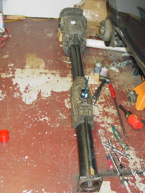
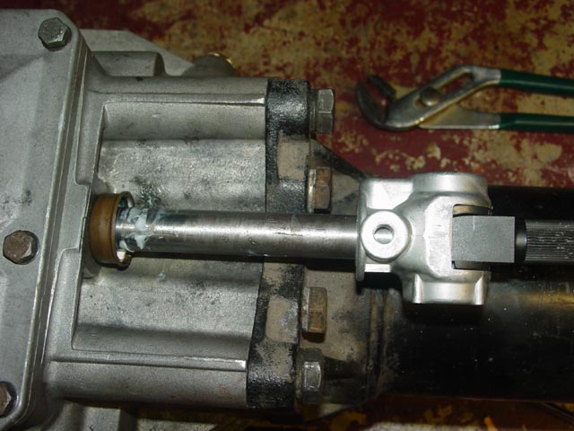
Picking up where I left off on the TT rebuild, here is the TT mated to the trans and torqued down.
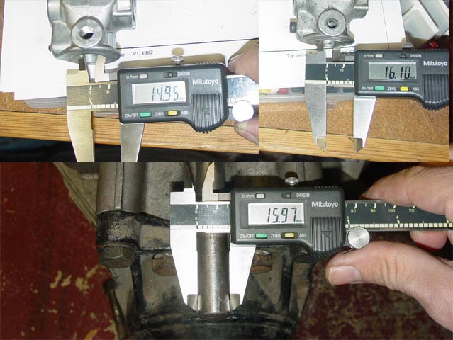
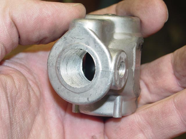
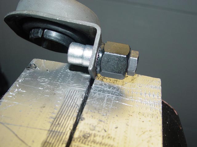
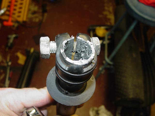
The first SNAFU with the shift linkage was discovering that the selector shaft on the transmission was a larger diameter than the replacement shift coupling(upper left). I was tempted to call it a day and call the vendor about the issue, but I quickly discovered that none of my online resources or PET showed a different part for the coupling. All years showed the same part number.

It's typical of Porsche to supersede with a part that doesn't work. Another example of this is the forward shift bushing, below. On the coupler, since it showed the same part for all years, it was hard to see where Porsche screwed up. However, the bushing that the selector shaft rides in, 928.301.502.00 "Guide Bush" is shown in PET as being used up to 1984. So the G28.07/08 seems to have the same diameterselector shaft as the '78. From this, I infer that the following transmissions would need a new shift coupler modified to fit: G28/03, 05, 07, 08, 09. Please contact me with any information you may have to help understand what transmissions have what size selector shafts.
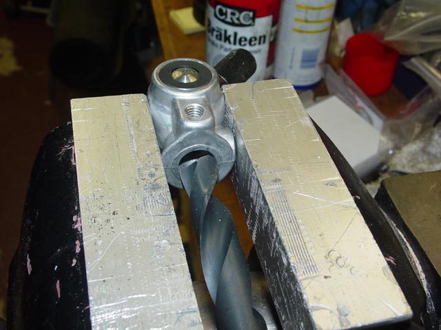
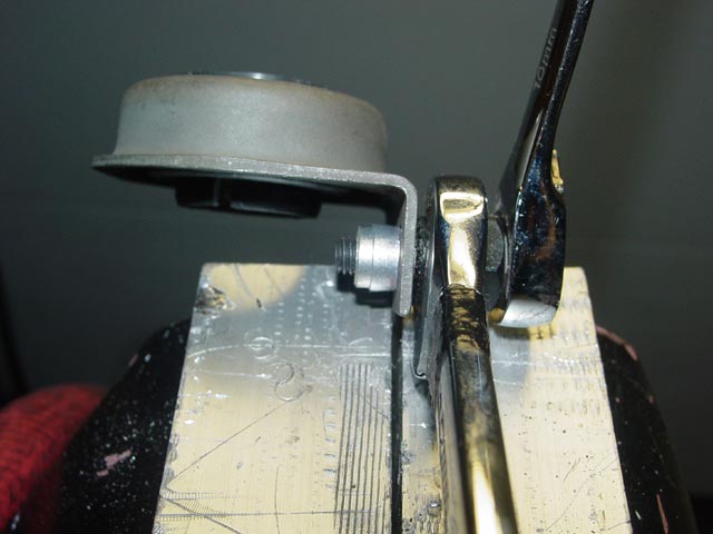
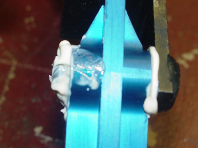
After doing a little head-scratching, I figured a 5/8" drill would get me in the ballpark, so I ran off to Home Depot to get one and drilled the new coupler out. I angled the spline shaft over to the side to get maximum depth with the drill. I lined the coupler up carefully in the vise so I could use the vise jaws to eyeball and guide the drill in straight.
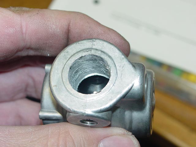
The resulting hole was still small, but close -- and a bit rough.
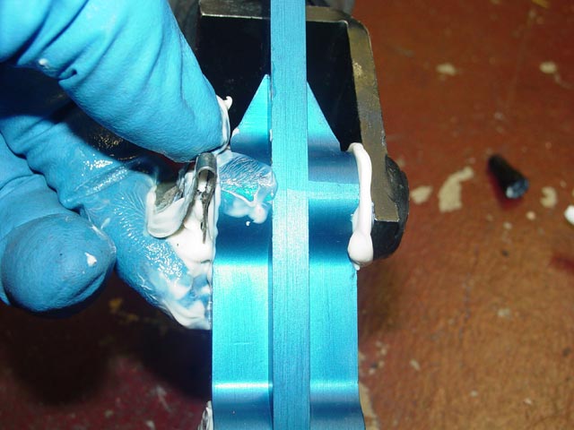
I used a well-worn 1/2" sanding drum on the Dremel to carefully open up the hole, test-fitting it to the selector shaft regularly.
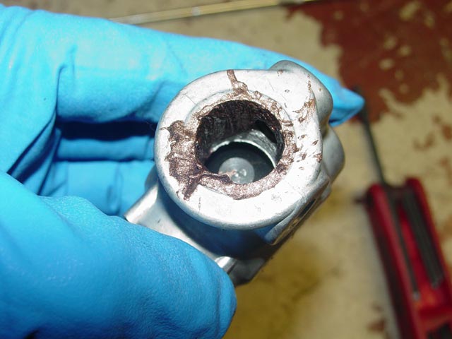
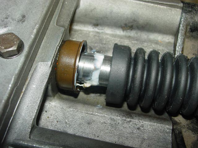
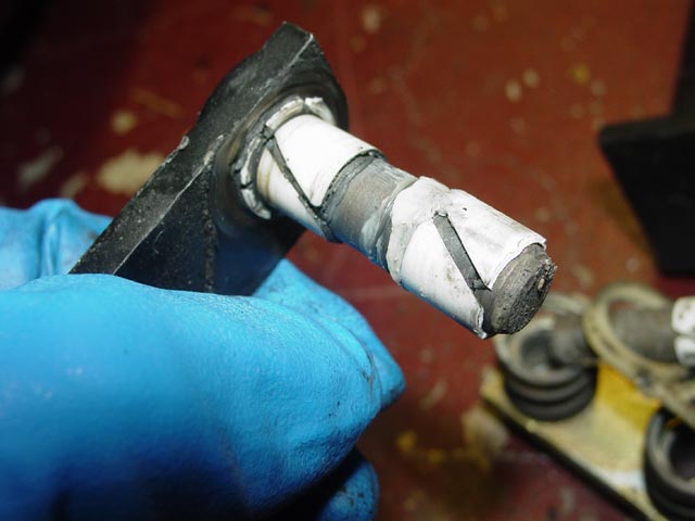
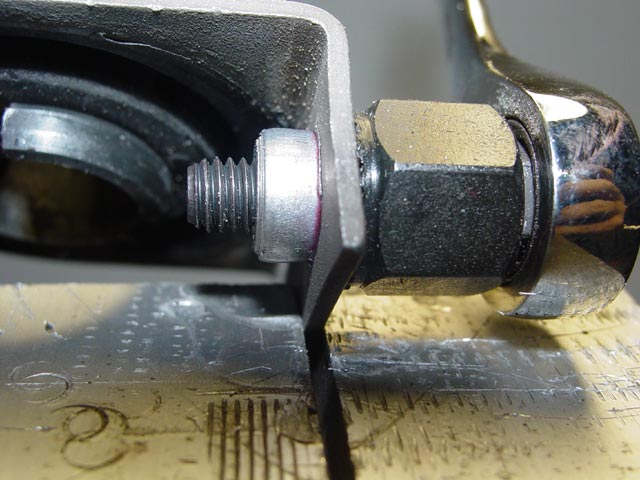
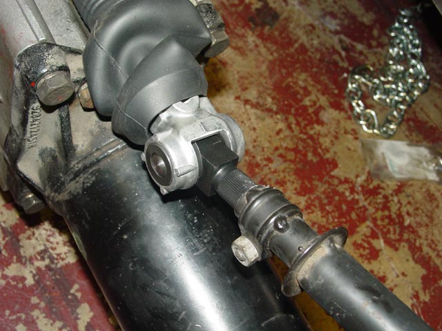
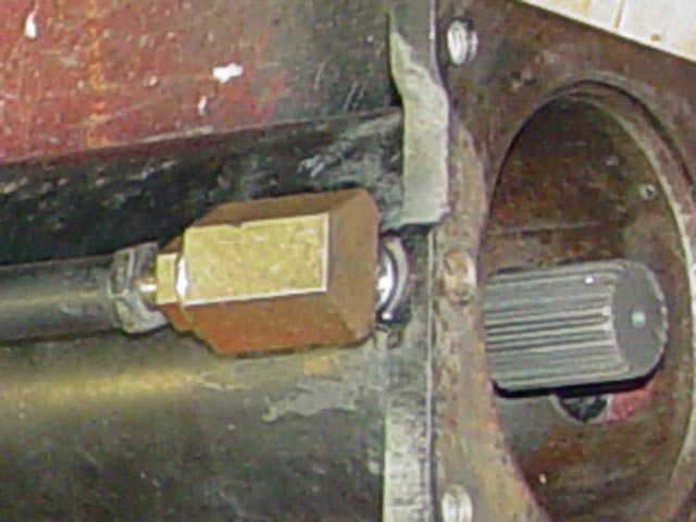
Finally I had it to where it would slip on the selector shaft. It was still a tight fit. Note the grease on the selector shaft near the seal, to hopefully increase the life of the seal. When I received the transaxle the seal was dry, and tended to fold under when the selector shaft was moved to the rear. This dab of Lubriplate cured the problem of the seal lip folding under.
Once I felt sure I was done making chips, I blew out the coupler thoroughly with compressed air to get rid of any chips and aluminum dust.
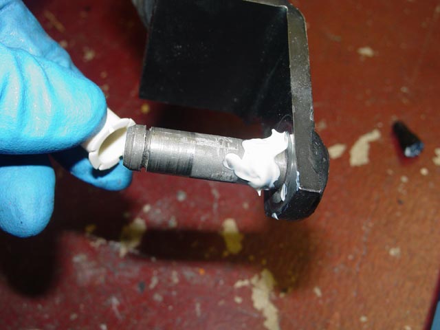
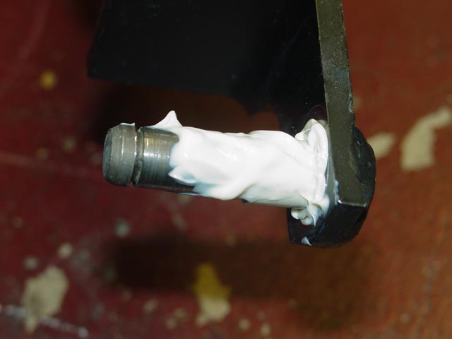
I then gave it a coat of copper anti-seize. If and when I ever need to take it off, I don't want it to be frozen to the selector shaft.
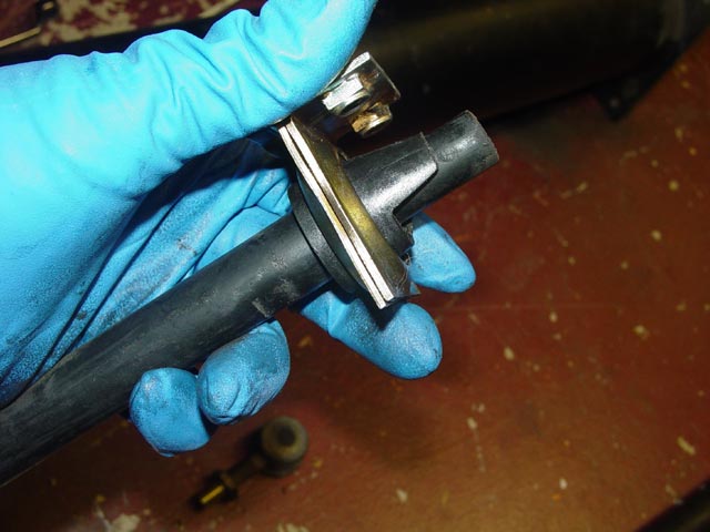
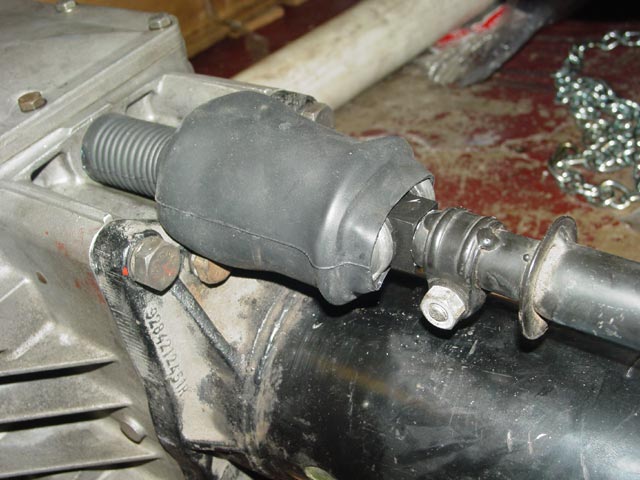
This is the new boot for the rear shift coupler. Note the groove just inside.
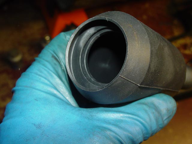
The groove mentioned above is supposed to fit over this ring welded to the rear of the selector shaft. It's a PITA to get it on there, but if you don't then the boot is not going to seal properly.
I slipped the boot over the selector shaft. The small end has a groove in it that snaps over this lip on the seal to hold it in place.
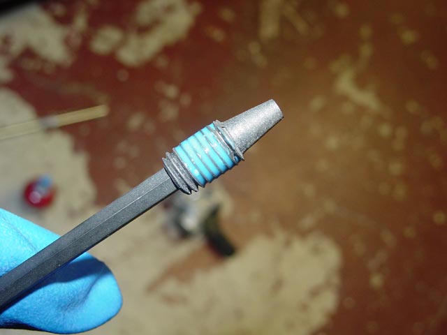
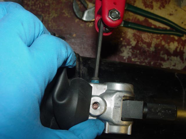
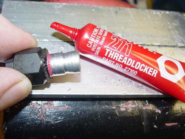
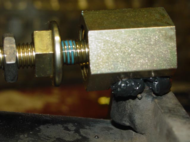
I put some blue loctite on the cone-shaped set screw that engages with the hole in the selector shaft.
While pulling the boot rearward, I installed the coupler then put the set screw in. This really only goes one way, the cone on the end of the set screw will pull the coupler into alignment as it engages with the hole in the selector shaft(assuming it's close to begin with). There is no torque spec given for the set screw, I went with the "tight-as-you-dare" approach.
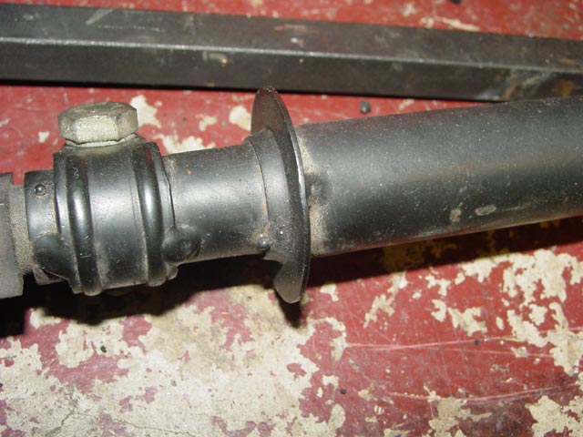
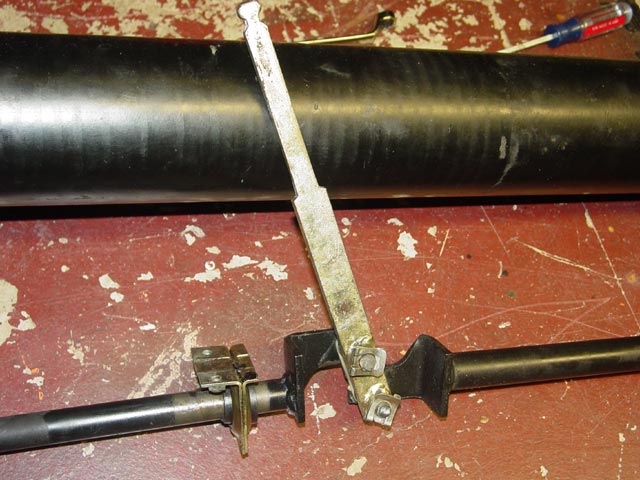
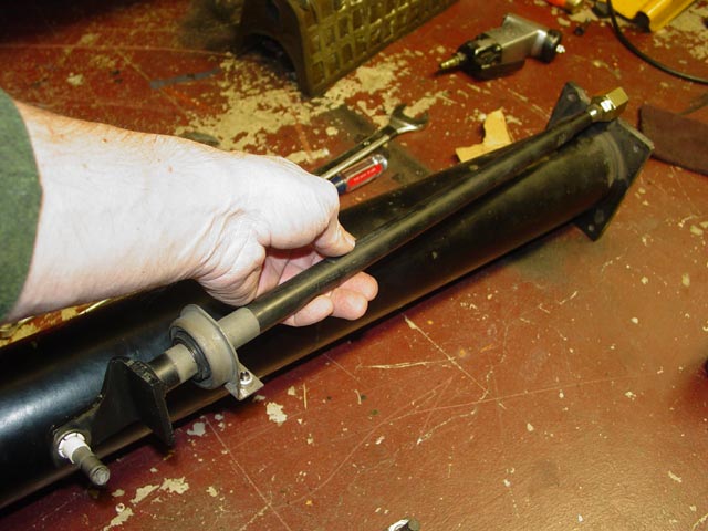
Time to turn my attention to the shift linkage. My first order of business was to take it down to its component parts so I could clean it up for reassembly. In case you found this page without reading through the disassembly section, the front section of the assembly is to the left, and on the forward rod you can see the forward shift bushing which attaches to the underside of the car.
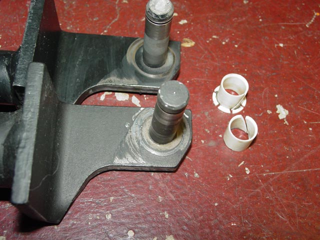
The clips that hold the shifter to the selector rods are very easy to remove, I just pulled the outer tab away from the pivot pin and slid the clip off.
The bushings are fragile, thin plastic. This one came apart just trying to pull the shifter off of the pivot pin. I wouldn't try to remove a shifter without having a new set of bushings on hand if it could be helped.
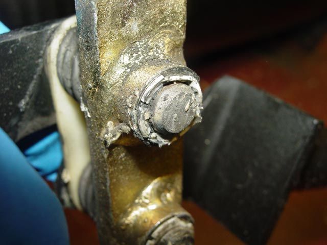
The "White Paste" grease had hardened up almost to the consistency of wax. The bushings didn't seem particularly worn, just brittle.
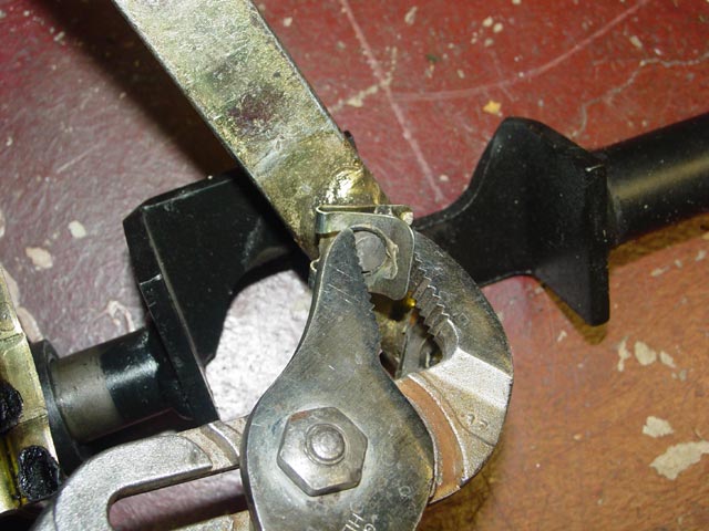
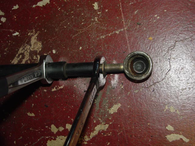
I took the old shift ball cup off with a 17mm wrench on the locknut and another on the flats that are formed in the shift rod. With the rod still on the car, this has to be a real challenge, getting a wrench on those flats to counter-hold. I suppose a workaround would be use a crowfoot wrench or to have a helper inside the car counter-hold with a crescent wrench on the L-shaped bracket that the shifter attaches to.
With the ball cup off I was able to slip the forward shift bushing off and get to work on making the replacement fit my car.
The part number for the correct forward shift bushing is superseded by the incompatible later version.
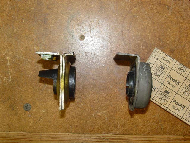
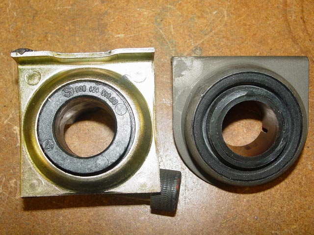
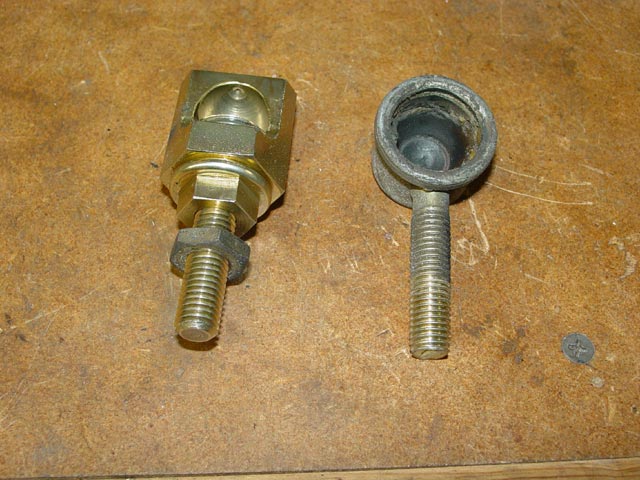
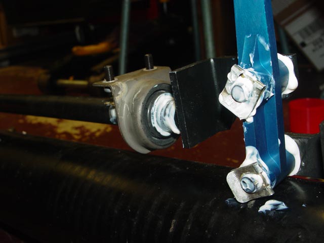
After seeing that the bushing was not very worn I debated whether to replace it or not. The plastic seemed very hard, even a bit brittle, so I figured it would be better to replace it before it broke. The original, on the left, is attached to the body via two 6mm bolts from above. The replacement, on the right, is attached to a bracket with studs on the torque tube with two nuts. 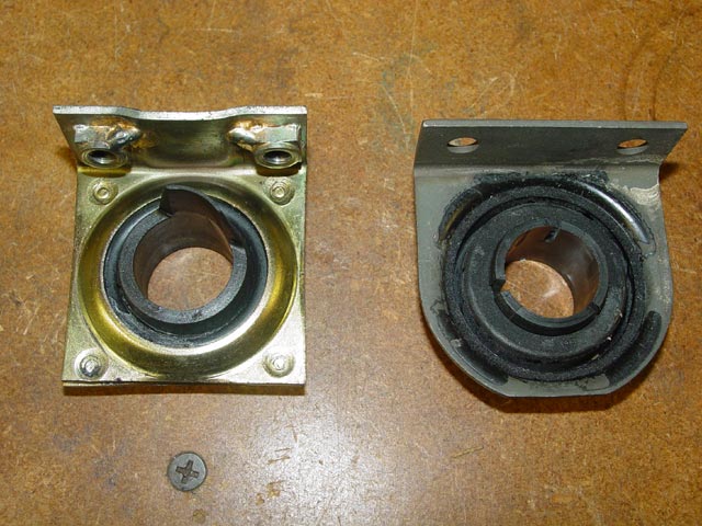
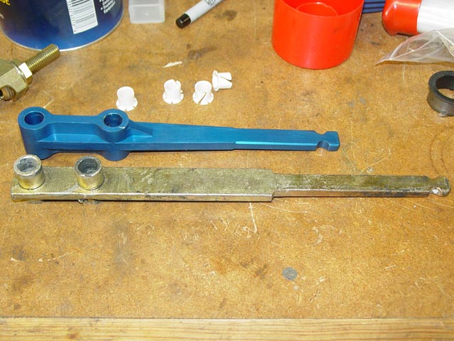
This is the Devek short shifter that I've had laying around for years. I hesitated to put it in at first because the transmission was occasionally very hard to get into gear, especially when cold -- so I didn't want to make it any harder. With a new transmission I hoped that wouldn't be an issue anymore. Between the shorter length above the top pivot and the greater distance between the pivots this shifter has about 1/2 the throw of the original. Add a new ball cup, coupler, and a rebuilt transmission to the mix, it ought to be pretty tight. My experience with the "Devek Radiator" had soured me on their "Quality Performance Parts" by the time I got around to needing the shifter, but that wasn't really a concern in this particular case. There's not much you can do to screw up a shifter.
I cleaned up the selector rods with mineral spirits as well as the bushings. I was curious to get a good look at the bushings, and as I mentioned earlier they were not particularly worn.
I have had good results in the past with Nutserts, I used them ~20 years ago to install the interior panels on my truck and they have held up fine. More recently I used them to fix the rear visors on the 928. Some alternate approaches would have been to get a later torque tube, or find out the dimensions and location for the bracket and fab one up and weld it to the torque tube. Another alternative would be to try to weld nuts to the new bushing, but the NutSerts were by far the simpler solution for me. Below is the installation tool and a couple of the Nutserts. I bought about a dozen of the Nutserts since 6mmx1.0 is so common. You never know when you'll need them.
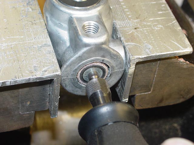
Comparison of the original hole size and the 3/8" hole required for the Nutsert.
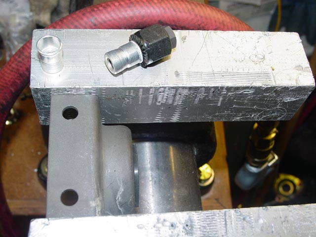
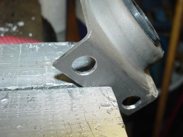
I wanted to be able to show a side view of the installation so I put the drilled part in the vise at an angle.
Whenever I use Nutserts I like to put a thin bead of loctite around the edge, just as insurance. I have some that have lasted decades without it, but it can't hurt, eh?
I pushed the Nutsert into the hole so it was bottomed out.
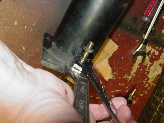
While pushing hard left with the gear wrench to keep the Nutsert bottomed out and a wrench counterholding the tool, I began to crank on the gearwrench to pull the threaded portion into the sleeve.
It's easy to tell when it's fully swaged, the threaded portion stops moving inside the sleeve and the torque required to turn the tool goes way up.
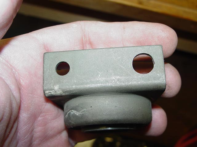
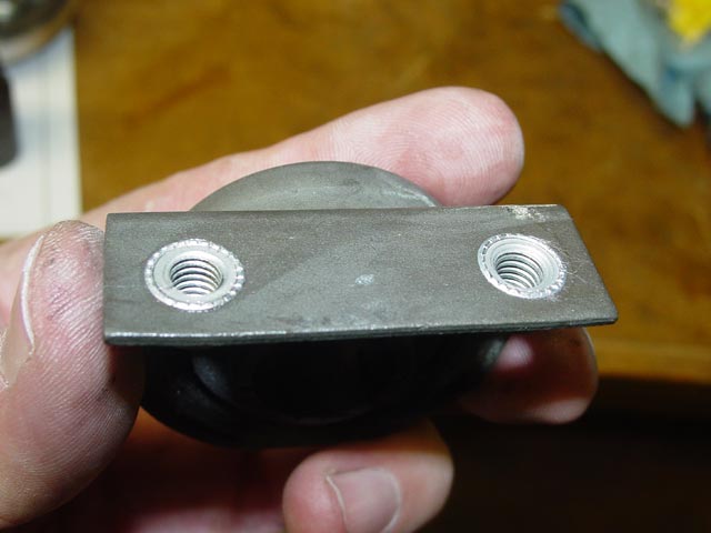
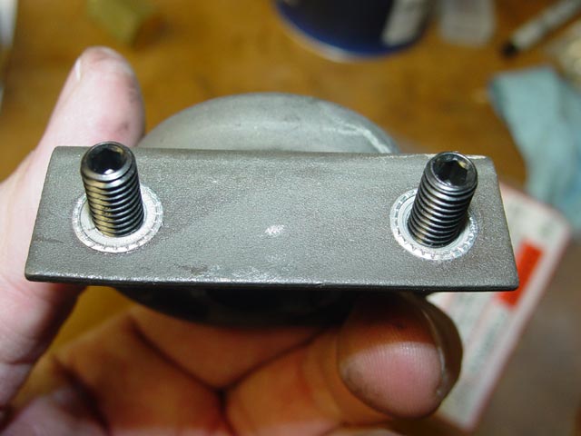
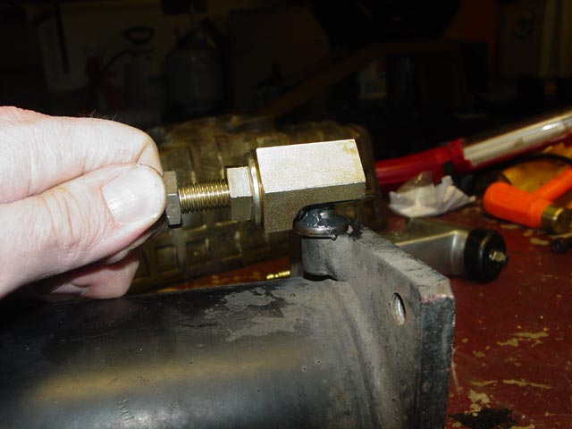
Bottom view with both Nutserts installed.
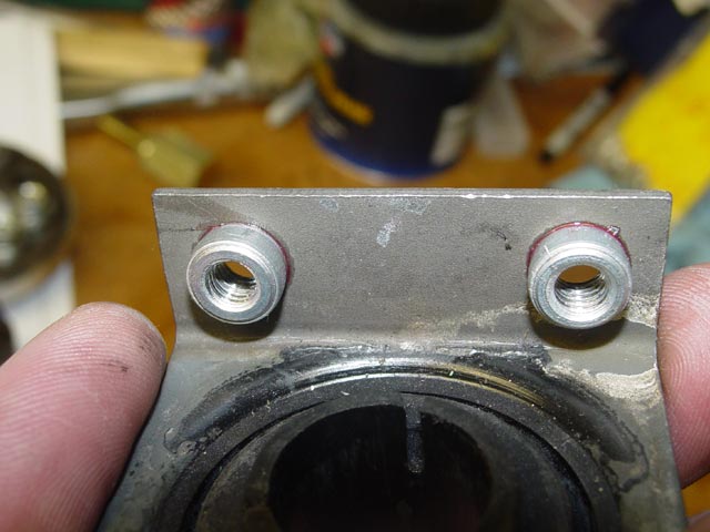
Top view with both Nutserts installed, after wiping away excess loctite. This part is now a direct replacement for the NLA original.
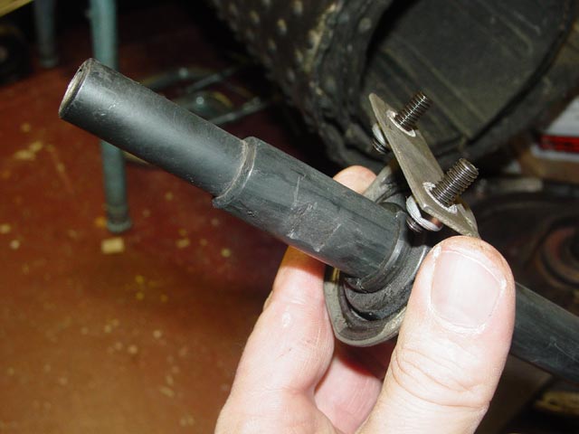
I thought it might be a bit of a challenge to get the bushing lined up with the holes in the body, so I screwed these long set screws into the bushing as an aid to get it positioned properly.
At this point I was able to slip the bushing over the front shift rod and forget about it for a bit. BTW, here's a better look at the wrench flats on the front shift rod.
I transferred the locknut from the old shift ball cup to the new one. The new one is Carl's design(928motorsports.com). It's a brilliant design, with a beefy steel body that hooks over the front of the shift ball and a large threaded portion with a concave face that screws up against the rear of the shift ball, allowing the desired play to be set. The large nut close to the body locks in this adjustment. It's a very nice piece, plated for corrosion protection, and only costs a few dollars more than the plastic Porsche version.
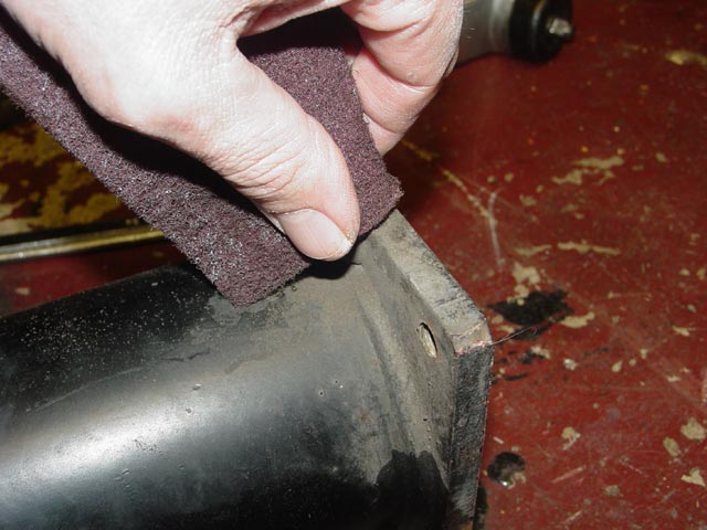
I cleaned the petrified grease, dirt, and the little bit of corrosion off of the shift ball with some scotchbrite.
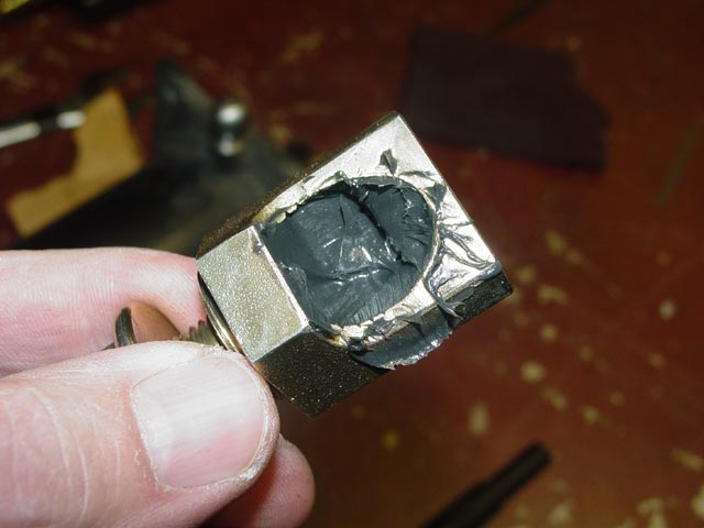
I put a nice glop of grease inside the cup...
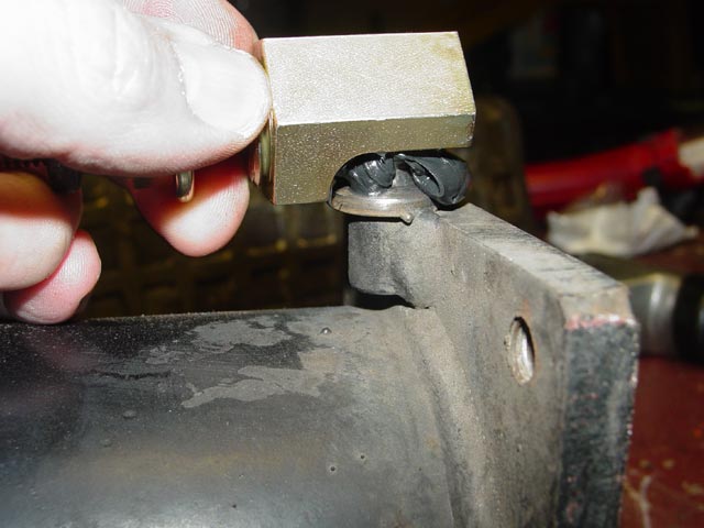
...and installed the cup on the ball.
I turned the threaded rod to move the concave adjustment screw forward, setting it finger tight. This gave nearly zero play yet allowed free movement. At this point I put some blue loctite on the threads where the locknut would end up.
Then I torqued the locknut down.
After cleaning up the excess grease, I double-checked the adjustment. Perfect!
I threaded the shift rod onto the ball cup. The old bushings were put onto the shifter pivot pins to facilitate adjustment. I didn't want to beat up the new bushings, since they are pretty delicate.
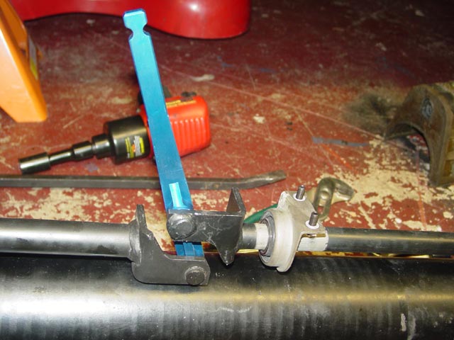
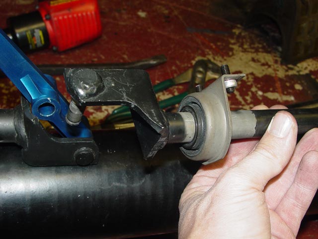
I gave the rear shift rod clamp that grips the spline on the rear shift coupler a healthy dose of anti-seize.
I slipped the rod onto the coupler spline...
...and snugged it up just enough that it wouldn't flop around, but it could still be moved.
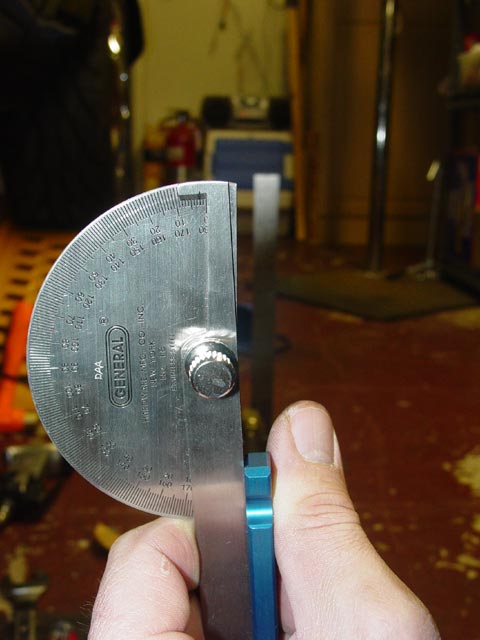
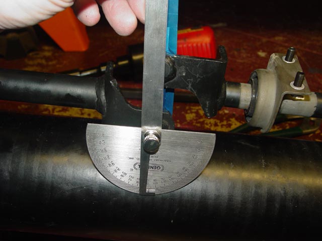
The WSM calls for the shifter to lean 2-3° to the left when the shifter is in neutral on the 2-3 plane. I slipped the shifter over the shift rods(no need for the clips just yet) and eyeballed it against the square standing on the floor in the background using this protractor. Once I was satisfied, I torqued the coupler clamp to spec.
At this point the shifter was angled much too far to the rear.
To correct this, I simply pulled the forward shift rod off of the shifter and threaded it further onto the ball cup to move it forward.
The WSM calls for the shifter to be leaning to the rear 2-3°. I was able to eyeball it pretty close with the protractor. At this point I locked down the locknut on the ball cup that binds against the forward shift rod, taking care to keep the ball cup level.
I didn't get a good picture of how I ensured that the front ball cup was level and not likely to bind, but the below pic from the WSM illustrates the issue nicely. The ball cup must have clearance at either end of travel between the R-1 plane and the 4-5 plane. Pic below shows shift rod in 4-5 plane.
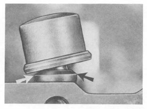
Here is a portion of the last pic on this page, blown up so you can see the ball cup. Pic below shows shift rod in neutral, 2-3 plane.
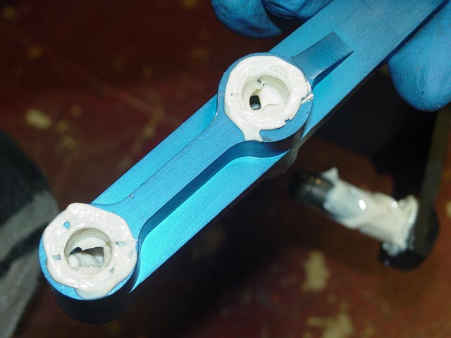
I wanted the pivots on the shifter to be well-lubricated, so I made an extra effort to fill all of the voids in the assembly with Lubriplate. I started with a nice glop of grease under the bushing.
After installing the bushing, I put a thick coat of grease over the outside of the bushing and over the pin where there will be a void inside the shifter.
Similarly, I coated the outside and inside of the bushings on the other side, and left a generous amount of grease inside the shifter.
I then slid the assembly over the pivot pins, holding the bushings to prevent them from slipping out.
Finally, I slid the clips into place. I'm not worried about the excess grease, if anything it will help keep the grease inside from drying out.
I also greased the forward shift bushing thoroughly.
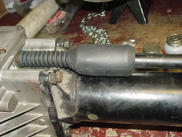
I worked the shift coupler boot over the ring on the rear shift rod. Note the lip that must be pulled over the ring for proper sealing.
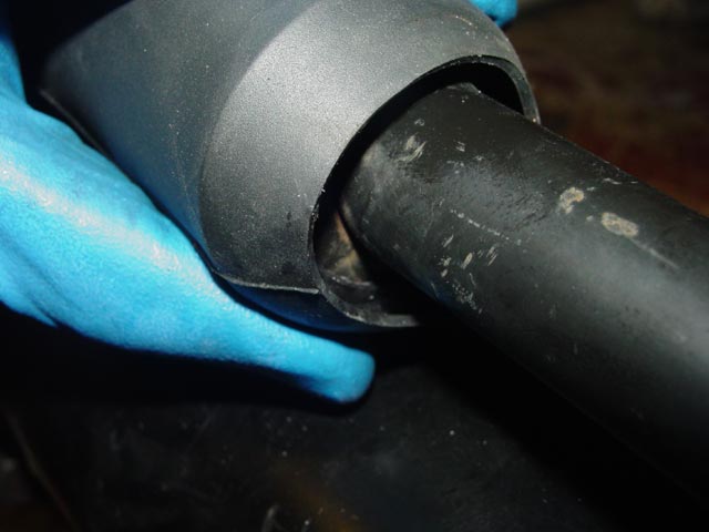
Rear coupler boot installed.
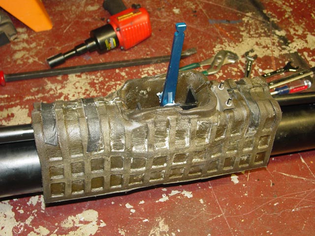
The next step was to replace the foam insulation that keeps hot air from getting into the console. The old tape that was on there to facilitate assembly was still sticky enough to hold things together. Once the assembly is in the car it is held in place by compression against the tunnel.
Below is the full assembly, waiting to be installed in the car. It only needs that "Add Oil" tag removed from the vent on the top cover of the transmission and it's ready to go. The transmission is propped up on wood blocks to keep it from tipping over. The core is packed up and ready to ship, top right of picture. Next step, Reassembly.