On this page I will run through the teardown. Since I knew the car would be up in the air for a while and I suspected that I would need some extra jackstands to support things during the project I decided to put the front on ramps. This meant that in addition to the two 3-1/2 ton jackstands that would otherwise be available, I had two 6-ton jackstands free for whatever I might need to use them on. Ultimately I only needed one of the 6-ton stands once the car was up, but I'm glad it was available since I was alone when it came time to drop the torque tube & transaxle assembly.
The preferred(and WSM recommended) approach to removing the transaxle is to completely remove the rear suspension and crossmember. It has been said that on the '78 cars, the transaxle can be removed without disturbing the crossmember, this is accomplished by removing the battery box and maneuvering the transaxle out through the space formerly occupied by the battery box. There were two reasons why I decided against this approach.
First, as best I could determine all of the people who had taken this approach had separated the transaxle from the torque tube in order to get it out. I did not feel this was a viable option, since it is easy to snap the input shaft fingers if the transaxle is allowed to hang from the driveshaft, and since I could not be sure I would have help for this part of the project I decided it would be safer to remove the torque tube and transaxle as an assembly.
Second, since I was planning to install Carl's(928 Motorsports) excellent steel front shift cup I felt that it would be preferable to get my shift linkage adjustments done with the trans and torque tube assembled on the floor. Even with Carl's assurances that it could be done with the drivetrain in the car, I felt it would be far easier to work with on the floor.
I had a debate with myself and some of the folks on Rennlist about whether I needed to drop the whole crossmember, the alternative being to just remove the 6 bolts that hold it to the body and remove the 6 nuts that hold the tops of the shocks to the body, swinging the crossmember down on the Weissach joints to provide clearance. I wanted to avoid having to have the car realigned since the rear bushings are worn to the extent that some of the adjuster eccentrics are maxed and I was worried that the car would be unalignable if I put it back together a little "off" from the original location.
I plan to replace rear suspension bushings as well as shocks at a later date, perhaps late summer/early fall 2009. Ultimately I decided to swing the crossmember down a few inches, just enough so that I could maneuver the TT/trans assembly forward and out. Once this was accomplished I intended to lift the crossmember back up enough to eliminate strain on the Weissach joints while I did other work and waited for parts. I was told to anticipate at least a two week wait for the rebuilt transaxle, and Constantine was still making final adjustments to the design and manufacturing process for his improved torque tube bearing carriers, so I expected a 2-3 week wait for those.
So, with parts ordered and a plan of action in place, it was time to get dirty.
 I wasn't going to daily drive the car anymore with the seized TO bearing, so I figured I might as well get a jump on taking it apart and determining what additional parts I might need. I did drive the car to San Jose Auto Steam Cleaning to have them give it a quick blast around the transaxle to remove most of the grease. I didn't ask them for a perfect job, just get the worst of it -- whatever they could easily reach. They only charged $40, I'm sure that if I had asked for and received a more thorough job it would have been more.
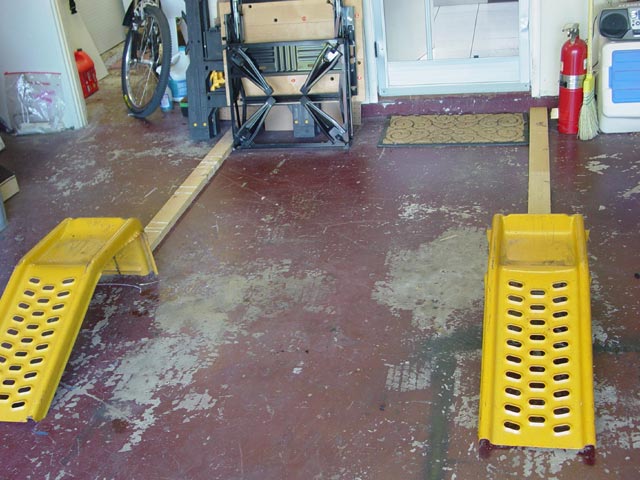
The first step was to determine where I wanted the car in my limited garage space. I wanted easy access from all sides, and of course I wanted to be able to close the garage door once the car was lifted. Once I had it in the position I wanted, I marked the front tire location on the floor with chalk and positioned the ramps over the marks.
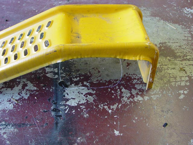
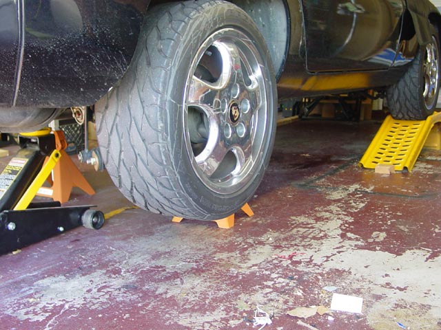
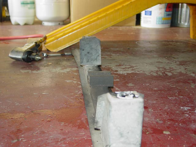
I discovered some time ago that I couldn't get the car onto the ramps in the garage because they tend to slide on the smooth garage floor. I resolved this by cutting some 2x4s to length to brace the ramps against the concrete foundation.
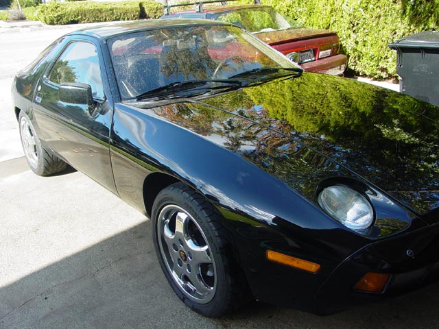
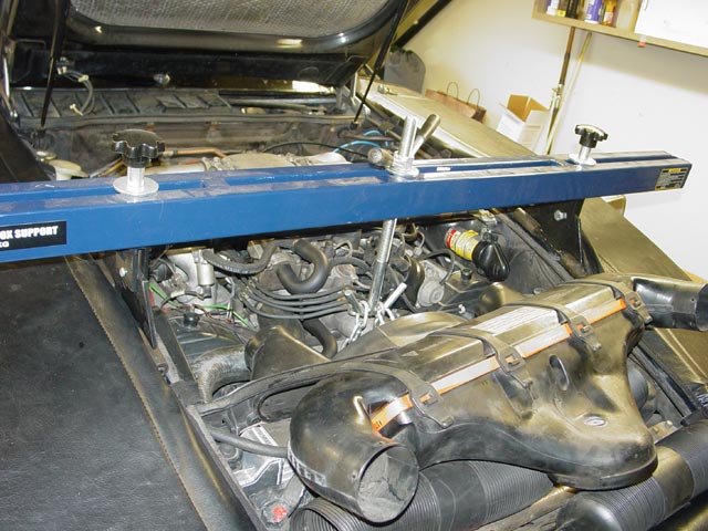
Whenever I use my service covers I make sure the fenders are clean so I am not grinding dirt into the paint. As you can see, the rest of the car needs a bath but I figured why bother? It's going to collect dust for a month or more anyway...
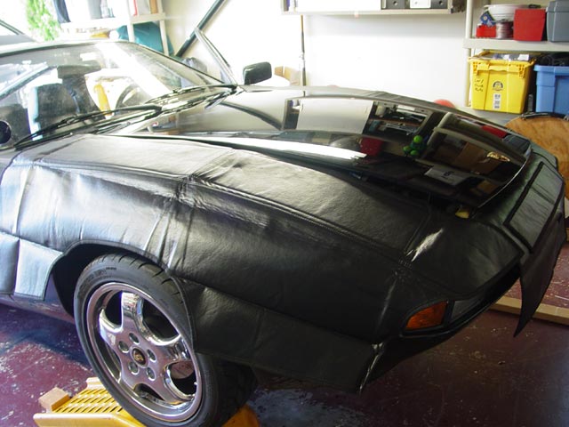
As soon as she was dry, I put her up on the ramps and put the service covers in place.
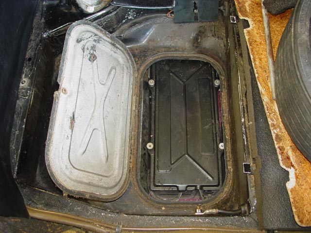
Next up, I figured it would be easier to pull the battery before lifting the rear end. As you can see, the lid on the '78 box(if you have it) makes it a bit more complicated than on later models.
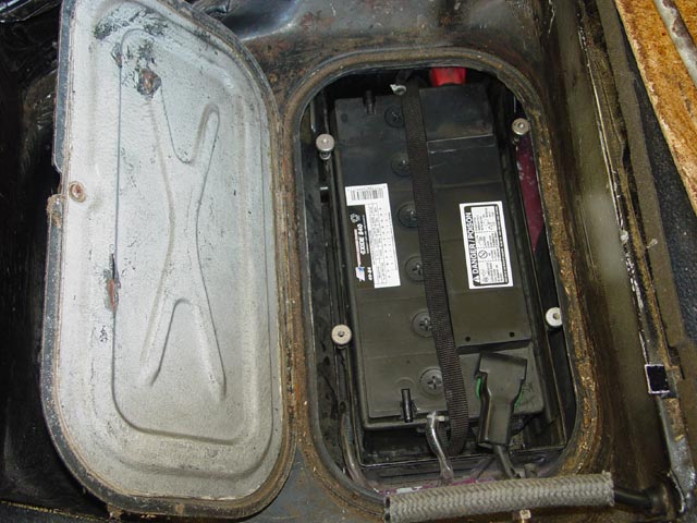
Lower lid removed, battery exposed.
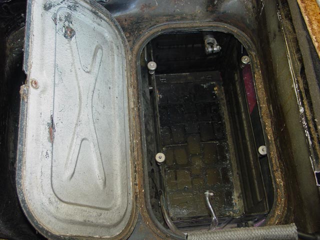
Battery out. I put the battery on a couple of 2x4s on the side of the garage.
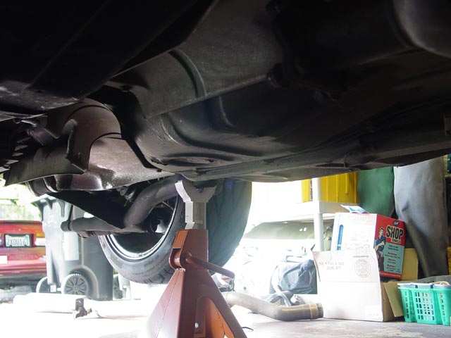
Next I lifted the rear of the car as high as I could get it with my jack, positioned the jackstands, then put a 4x4 between the jack and the rear crossmember to lift it a few more inches. I kept pushing the jack forward as I lifted to keep the front tires in the wells on the ramps. If I had not paid attention to this, and the front tires rolled over the lip on the ramps, it could have been ugly... As always when lifting a car, once it was settled on the jackstands I gave it a firm shake in all directions to make sure it was stable before proceeding.
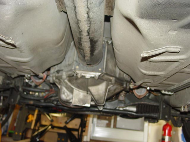
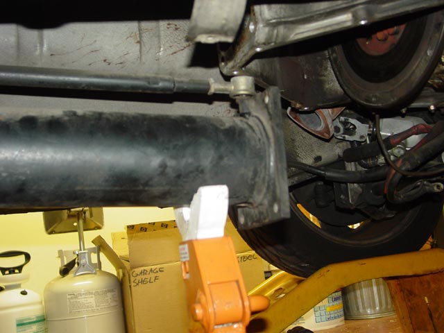
The first part to come off was the cross brace that runs under the exhaust pipes and the bellhousing.
Next out was the cat-back exhaust...
Then the cat itself came out.
Then the heatshields were removed from the front. This took a bit of patience -- the rubber insulation on the firewall had melted a bit and stuck the front heatshield to its mounts. I freed it with a utility knife and worked it loose. All hardware was put back where it came from, for example on the cross brace mount points(visible below), or bagged & tagged, for example the heat shield hardware.
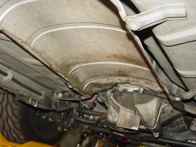
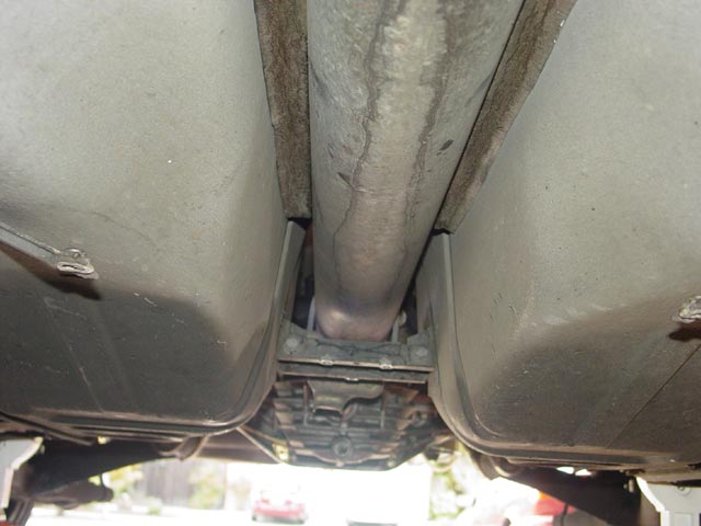
The rear heat shields were a bit more straightforward -- they came right out. I think the liquid marks on the underside of the TT are from the air conditioner drain dropping water on the side of the TT. Additionally, I used some evaporator cleaner to flush out the evaporator, which must have added to the mess.
When I dropped the lower bellhousing I found this piece of plastic inside. I wasn't sure at this point where it came from, but after looking at the replacement throwout bearing I figured that's where it came from. On the early cars the starter is attached to the lower bellhousing instead of the steel bracket that mounts to the block, so the starter had to come off in addition to the slave cylinder. Note the hardware threaded back into the lower BH... Also, I tie-wrapped the clutch slave cylinder to the swaybar so it would not get bumped inadvertantly, and I tied a piece of rope from the clutch pedal to the steering wheel to prevent myself from accidentally popping the rod out of the clutch slave.
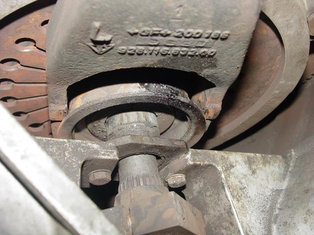
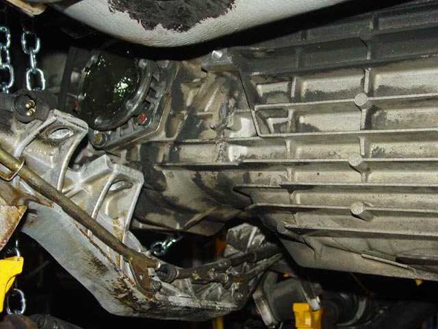
First look at the TO bearing. It appears that the grease worked its way out of the bearing and dripped down the release arm. The guide tube was dry as a bone too. I guess I should have greased this up in my first weeks with the car when I adjusted the intermediate plate, but in my ignorance I left it be and didn't dig deeper since it was operating properly. I now consider this a maintenance item -- I plan to get into the clutch and inspect/lube as needed every 25K or so. At this point I had popped the release arm free from the pivot ball(or so I thought). I removed the pinch bolts on the collar that connects the drive shaft to the stub shaft, and pushed the collar back into the torque tube. I removed the two guide tube bolts and the six bolts holding the pressure plate to the flywheel and the clutch came right out. I was very careful to not drop it on my head, a rite of passage that I wanted to skip.

Note that on the very early cars there are no dowel pins locating the intermediate plate or pressure plate to the flywheel, these parts are kept concentric by engaging with a lip on the flywheel. The above mentioned steps involved some back and forth between the clutch area and the crank pulley where I was turning the crank with a wrench. I've heard that turning the engine with a screwdriver on the starter ring can damage the teeth on the starter ring and I wanted to avoid that.
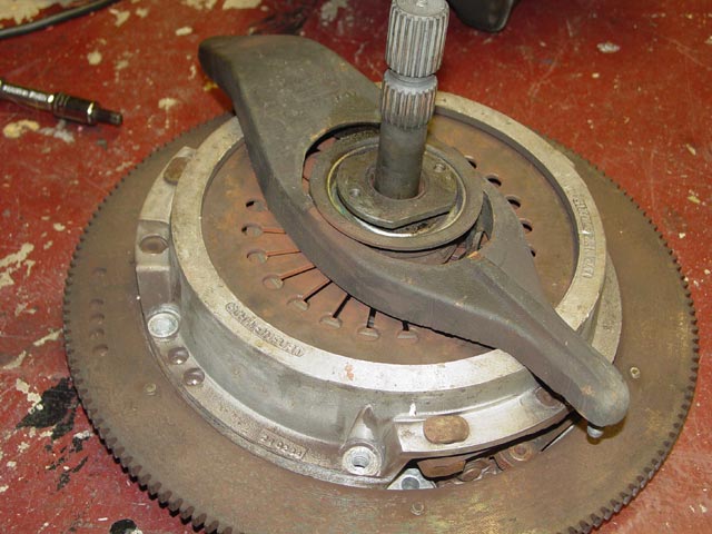
Here is the clutch pack out on the floor. Note that the pivot ball is still attached to the release arm. Not a good sign. I ended up having to replace the upper bellhousing. Details of why the upper BH needed replacement, of clutch pack disassembly, loose TO bearing pieces, and other issues found during disassembly are on the Analysis Page.
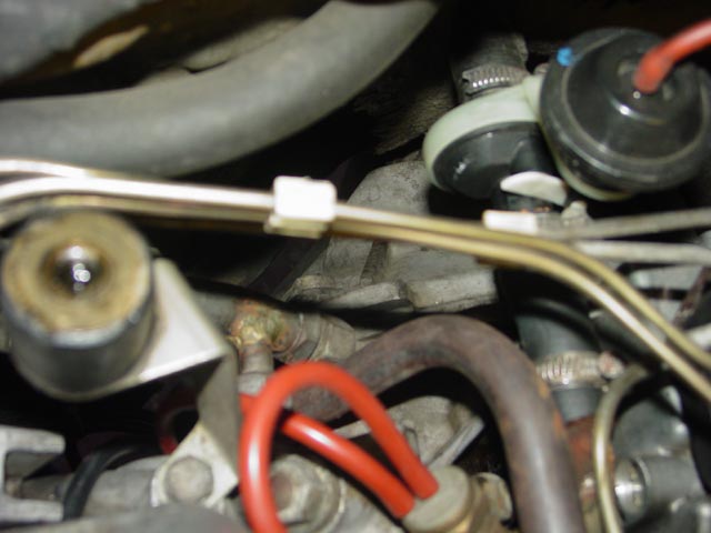
The upper bellhousing bolts are a bit of a pain to get to, especially this one, on the passenger side. I had done this before with Bill Ball, on Matt Edco's car but the different equipment on the '78 required a different approach. For the life of me I could not get to this bolt from above, though I could see it. The wrench would only engage in one position, and in that position it had no clearance to move to loosen the bolt. The bolt head is visible halfway between the loop of orange vacuum hose and the plastic clip on the injector lines, center of pic.
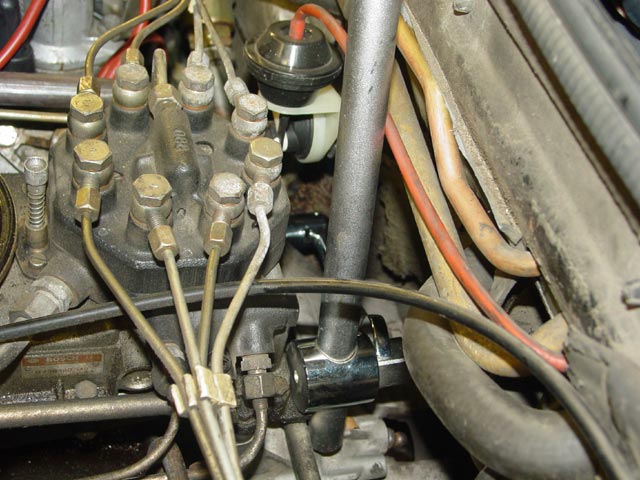
Luckily the upper BH bolts are 19mm, so I was able to use a 3/4" breaker bar engaged with the open end of a swivel-end wrench to gain some leverage. I tried a number of different approaches; this is what finally worked. Once I settled on this method the bolt broke free with little effort.
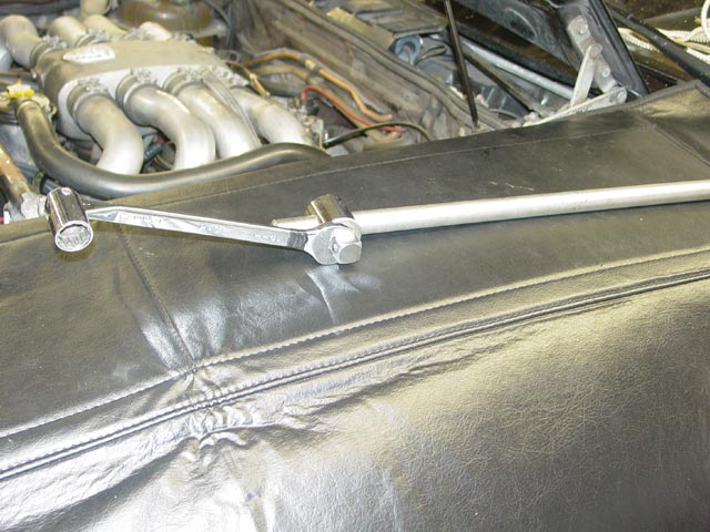
The driver side upper BH bolt came off just as easily, with the wrench rotated 90� on the breaker bar as shown below. I would remove the lower bolts on the upper bellhousing later, after the torque tube was disconnected.
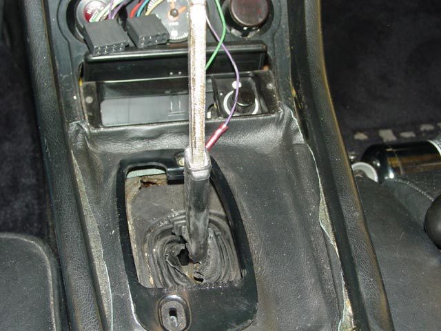
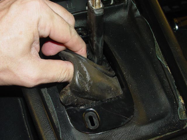
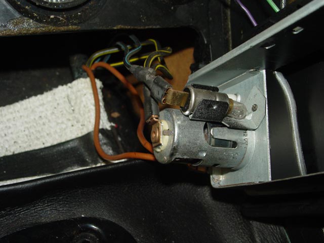
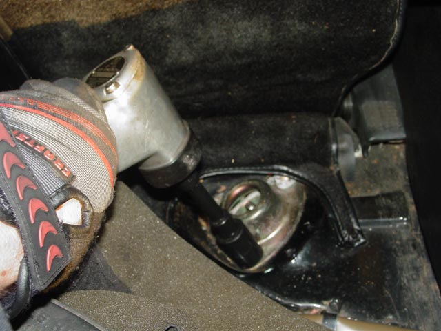
Next I needed to remove the shift knob and boot, also I needed access to the bolts that hold the forward shift bushing to the body. Later cars have the forward shift bushing attached to the torque tube, and in that case it is only necessary to remove the shift knob and boot. In this pic I have done so, and additionally I removed the radio and the trim that extends from behind the shifter to the center vent. The shift boot is attached to the shift gate by means of a drawstring that closes the large end of the boot over the exposed ridge on the shift gate. The connectors at the top of the pic are for the radio. Note that there was a screw missing from the shift gate/boot mount. There is a clip that that screw engages with; I eventually found the clip and replaced the screw(Reassembly Page).
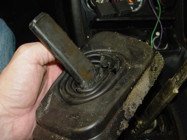
I carefully removed the lower shift boot. The flap that you see at the lower left extends around the boot, and it sits between the tunnel and the interior insulation. It was a whole lot easier to remove than it was to install the replacement.
Lower shift boot removed.
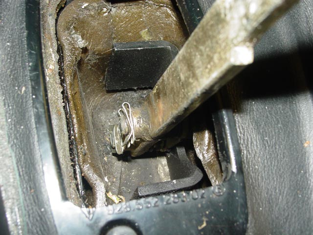
Shifter pivots and retaining clips exposed. I could have removed the shifter at this point, but I decided to leave it to see of I could maneuver the trans/TT assembly out of the car with it in place. This is a tight area to work in, by some accounts a PITA to get those clips off and back on. Consistent with my goal to pre-assemble the shifter upon reassembly, I decided to leave this assembled in order to determine if there were going to be any clearance issues.
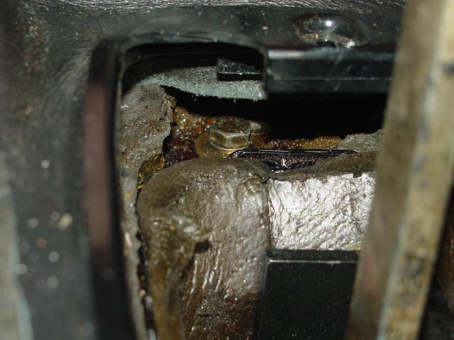
With the lower shift boot removed, I could see the bolts that hold the forward shift bushing to the body. It's probably possible to get to them from here, but there is an easier way pointed out in the WSM...
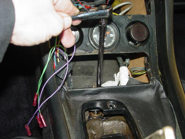
Removing the ashtray provides easy access to the bushing mount bolts. This pic was taken as a reference to ensure that I put the wires back in the correct locations upon reassembly.
The bolts are easily accessed with a 10mm universal socket and extension through the ashtray opening. They are easily lost, as are the washers... so be careful!
I wanted to give the transaxle plenty of time to drain while I was occupied elsewhere on the car, so I positioned my drain pan and pulled the plug. The lube looked pretty good for having 33K miles on it. Interestingly, the rear drain plug has no magnet on it.
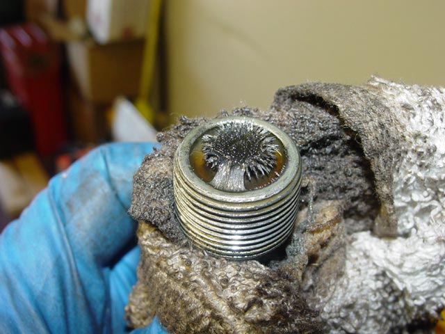
I wanted to get as much lube out of the transaxle as possible for shipping, so I pulled the front drain plug as well. The front drain plug did have a magnet, and on casual inspection it looked pretty hairy and scary.
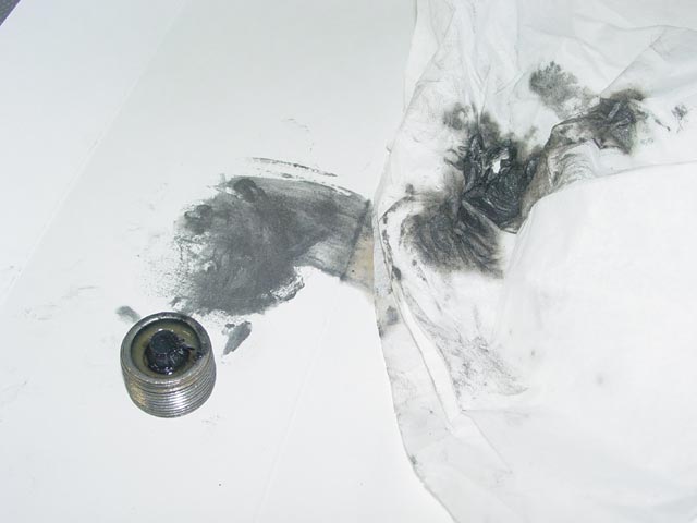
When I cleaned off the magnet and smeared the result on a piece of paper and a paper towel the metal that came off turned out to be a very fine powder. Not bad -- I was expecting chunks.
While the transaxle was draining I removed the rear wheels and calipers, wiring the calipers up in the wheelwells so there was no strain on the brake lines. The brake hoses are definitely showing signs of age, but I think they will make it a few moths until I am ready to switch over to S4 brakes. The passenger side was easy to tie up to one of the fuel line mounting straps.
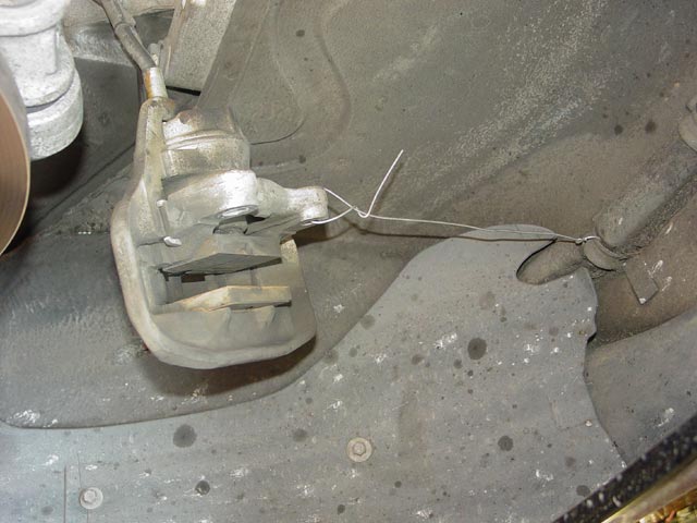
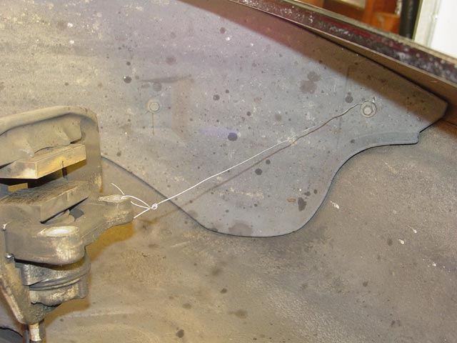
The driver side had no convenient place to hang the wire, so I loosened one of the liner bolts, wrapped the wire around it, and tightened it back up.
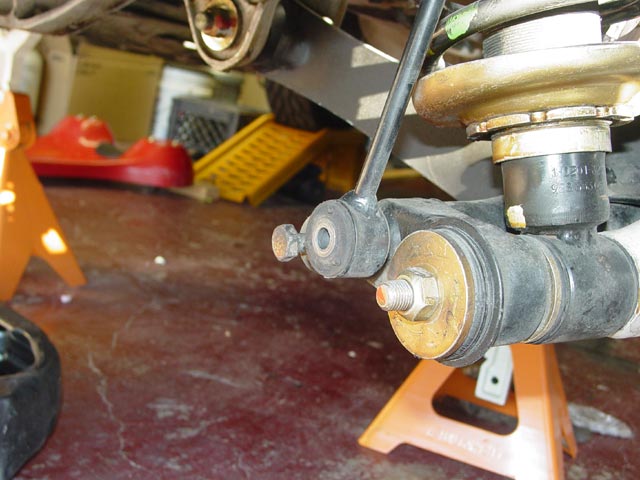
I also disconnected the drop links, replacing the bolts on the suspension arms to help keep track of them.
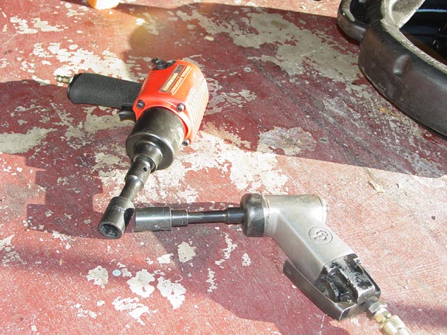
This 3/8" Chicago Pneumatic air wrench was invaluable during the teardown. It is light and compact, and had plenty of oomph for every fastener that I used it on, except for the caliper bolts. For that I broke out the heavy artillery. The Central Pneumatic(Harbor Freight) 1/2" "Earthquake" impact wrench is claimed to produce 625 lb/ft of torque. With the regulator set to the middle position, a quick tap on the trigger freed and spun each caliper bolt almost all the way out. Impressive!

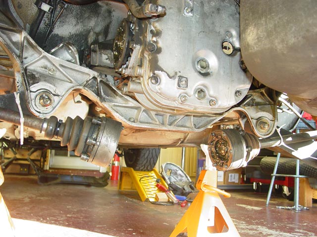
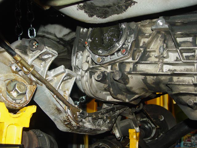
I released the parking brake so I could spin the axles around. With the transaxle drained, I replaced the drain plugs so it wouldn't drip on me and removed the battery box. It is attached to the studs on the rear differential cover and two bolts that screw into the bosses just visible above and below the trans output shaft. It's a lot easier to get at the CV bolts with the battery box out of the way. The 3/8" air wrench made short work of the CV bolts, and I tie-wrapped them to the suspension arms to keep them from flopping around. On the early cars it's pretty easy to completely remove the halfshafts(especially with air tools) since you don't have to break loose the big 332ft/lb axle nut, but I didn't see any point in going to the extra effort.
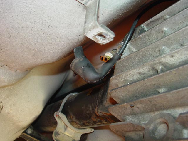
The reverse switch is on the upper front driver side of the transmission. Unplugging it is easy enough, but also be sure to remove the steel clips that attach it to the top fin along the side of the transaxle.
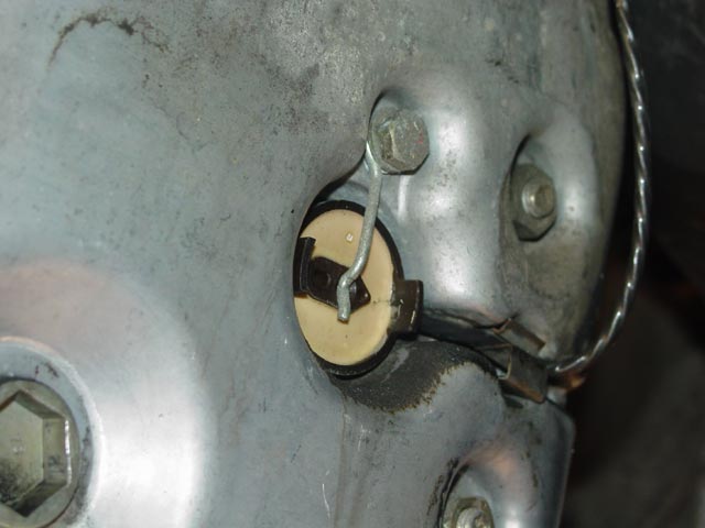
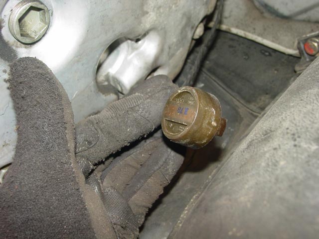
The speedo sensor, for the uninitiated, is held to the rear differential cover with a single bolt and wire arrangement. The sensor wire is held by a retaining clip pushed into a recess in the housing.
There is no seal here, the sensor drops right out once the bolt and clip are removed.
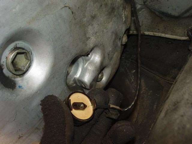
Here's the front side of the sensor, for the curious.
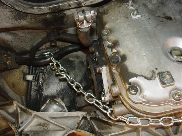
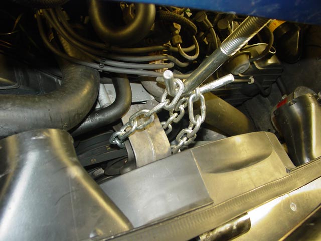
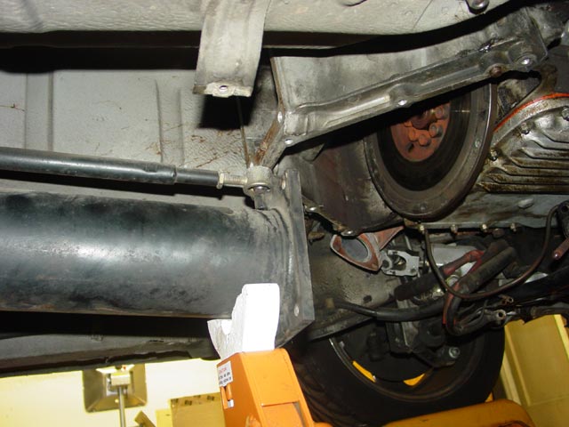
Preparatory to dropping the crossmember, I duplicated and improved upon the Porsche tool(which is a fixed-length cable) by using a few dollars worth of chain and some S-hooks from the local hardware store to support the transaxle from the swaybar. Per the WSM recommendation I attached one end to the bend in the swaybar...
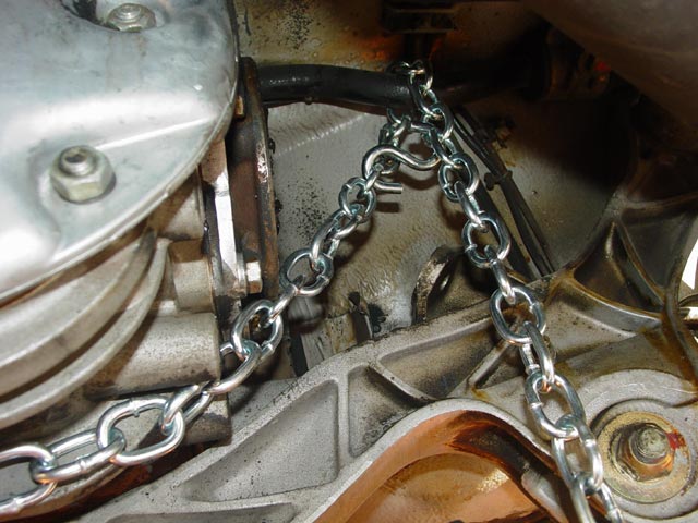
...On the passenger side(not that it matters which side) I connected the S-hook to the bend on the other side of the swaybar and let the extra chain hang down. Not shown, I removed the two bolts that attach the transmission mounts to the crossmember, then with a jack and a piece of 4x4 I lifted the transaxle until it contacted the underside of the body, then took as much slack as possible out of the chain. Once I lowered the jack the transaxle was hanging from the chain, not touching the crossmember.
After marking the shock mounting studs(they only fit one way, but I didn't want to have to guess on reassembly) I removed all six of the nuts holding the shocks to the body.
Before proceeding I thought it prudent to support the engine to keep it from rocking forward, which would only make it more difficult to line things back up later. Since I was not trying to support the whole weight of the engine, I felt that one chain was more than sufficient.
I would not recommend supporting the weight of the engine from this bracket, but for my purposes this was plenty strong enough.
Before dropping the crossmember, I marked all of the mounting locations with a bit of grey primer so I could get them back in the exact same position. I didn't want to scribe them since that would require scribing through the undercoating and perhaps the paint and primer as well.
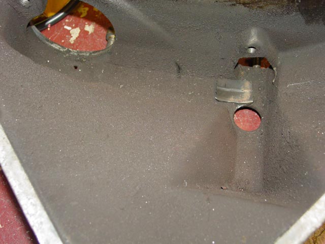
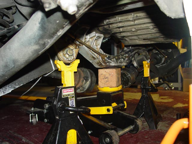
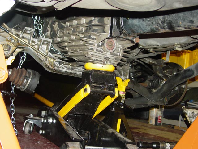
Dropping the crossmember at this point was very easy. There are six bolts that hold it in place, two at each end and two more, one adjacent to each transmission mount just inboard of the lower control arm bushing. You can see one of these inner mounting tabs in the pic below, just to the left of the shadow from the flash. The tab to the right of the shadow is for the transmission mount. First I put the jack under the crossmember to hold it up, then removed the bolts, and lowered the jack. I lowered the crossmember to the point where I could see that it was putting some strain on the Weissach joints, then jacked it back up a couple inches and supported it on jackstands. I didn't want to put undue strain on the bushings. In fact, after removing the transaxle, I jacked the crossmember up a couple more inches.
At this point the job slowed dramatically since I did not have help and needed to be very careful not to drop the transaxle. I didn't want to damage a good core, and I especially didn't want to drop it on myself. I put a jackstand under the front of the torque tube and removed the bolts holding it to the upper bellhousing.
Next, I jacked up the transmission to relieve the tension on the chain, and moved the S-hook to provide a couple inches of slack. I lowered the transmission carefully, walking the S-hook down the chain so that it never had more than a couple of inches of slack at one time(safety before speed). I stopped when the trans mounts were about 1/2" above the crossmember.
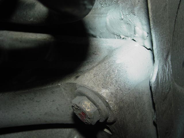
At this point I removed the transmission mounts from the transmission. This is necessary since the transmission tunnel under the car narrows toward the front of the car and the mounts will stop forward progress before you clear the crossmember. They are held on by one bolt each. Technically I could have done this earlier, but by waiting until this point it was a straight shot with an air wrench to get the bolts out. Both mounts were beginning to show cracks in the rubber. You can see a crack on the top of the rear block of rubber in this pic. It looks superficial but later I probed it with a feeler gauge -- the crack was about 5mm deep.
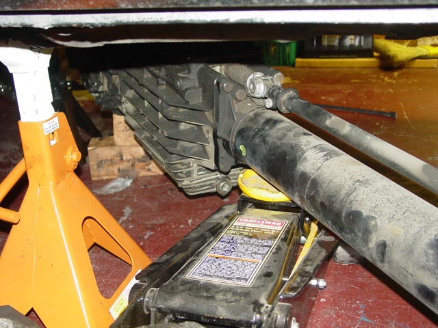
By this time the transaxle was low enough that I could reach it without a 4x4 in the jack. I discovered that with the jack under the front drain plug as shown, the assembly balanced almost perfectly, a bit heavy at the front. I could tilt it fore or aft with one finger. I was still being extra careful though...
I kept the torque tube supported as long as possible with a jackstand.
As it moved forward it needed to tilt down more, lower than the jackstand would fit under so I used about an 8" length of 4x4.
Still moving forward -- it's a pretty tight fit. This is about where I started getting nervous, since the transaxle was so far forward that the chain would no longer stay put under the transaxle. A slip at this point could get messy.
Almost there... about another inch to go to clear the crossmember.
Finally clear of the crossmember. It was too early to relax though, I needed to get it off of the jack. It was too tall at this point to roll it out from under the car. It was much too heavy to lift off of the jack while laying under the car.
The torque tube had to be supported still, or the rear of the transaxle would stick against the underside of the car. The shift lever was tall enough to be a problem too.
I popped the front ball cup loose and laid the shifter down so the TT would swing out from under the car. There would be enough room to reverse the process with the short shifter in place and the ball cup installed. It would have been a bit trickier if I were putting it back together with the original shifter. I would have had to disconnect one of the pivot pins at the shifter in that case.
I supported the assembly with some wood blocks under the differential housing, which allowed me to reposition the jack under the torque tube. The assembly was no longer balanced at this point, but I could maneuver it well enough by pushing down on the forward end of the torque tube with maybe 30 lbs of force. Doing so allowed me to lift it off of the blocks, at which point I lowered the jack as much as possible and rolled the assembly out from under the car.
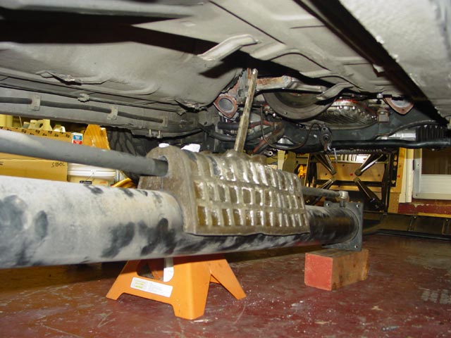
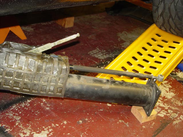
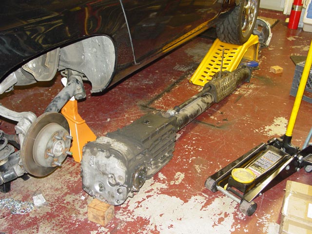
After a bit of jockeying the assembly was out, though there was little I could do with it at this point -- the rebuilt transmission had not yet arrived, nor had the torque tube bearings from Constantine.
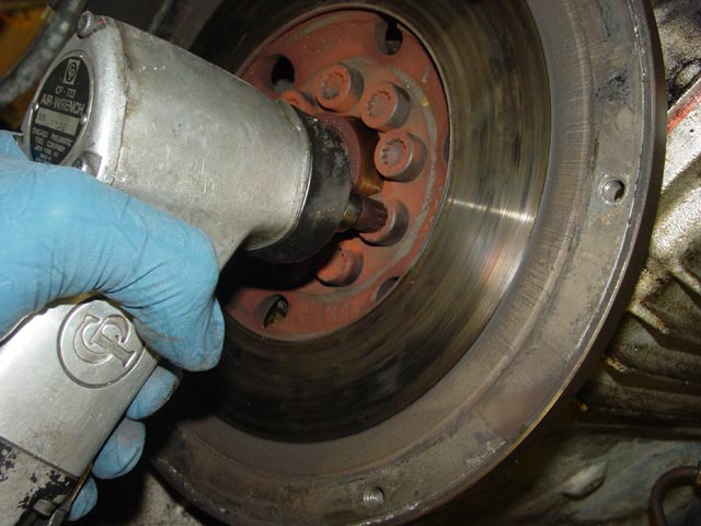
I did, however, have my resurfaced and balanced flywheel/clutch pack back from the machinist along with the replacement upper bellhousing so I went ahead with that end of the project. Since even my compact air wrench could not reach all of the flywheel bolts without the tedious and repetitive turning of the crank(I could reach maybe 2 or 3 of the bolts at a time) I went ahead and removed the remaining two bellhousing bolts and zipped the flywheel bolts out.
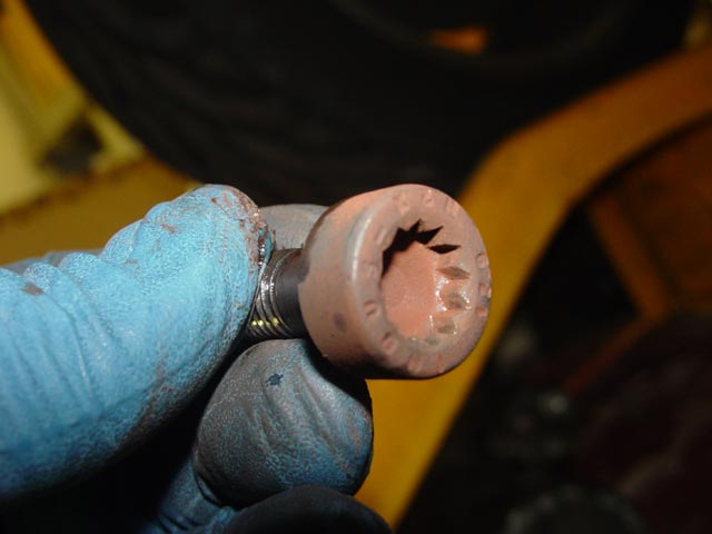
I have heard that these screw heads strip easily because of the shallow tool engagement, but I had no problems at all. I barely even left tool marks on the bolts, though I replaced them just the same -- cheap insurance. I think the problems arise from the tight working space and the high breakaway torque. It takes a bit of extra care to remove them under those circumstances IMHO.
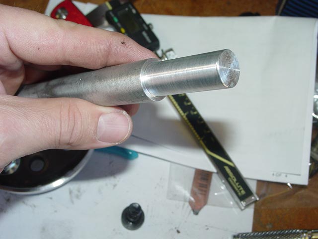
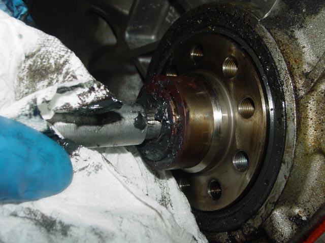
As an experiment I wanted to try the "hydraulic" method of removing the pilot bearing. This method involves filling the cavity in the crank forward of the pilot bearing with grease, then pounding a dowel in to force the bearing out due to the incompressibility of the grease. I had the machinist make up an aluminum dowel out of scrap for the purpose. It took him less than 5 minutes on top of the other work he did for me, so he charged me $5. The working diameter is about 14.8mm.
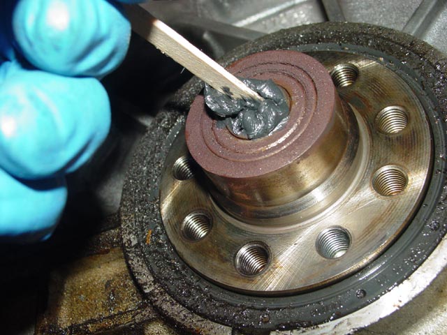
I used a popsicle stick from the revlimiter's craft drawer to work the grease into the cavity. It took me a couple of tries to get the air bubbles worked out. The first time I inserted the dowel it felt spongy, indicating that there was quite a bit of air in the cavity.
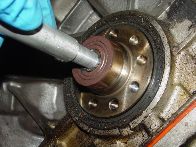
Once I had most of the air out, and I felt firm resistance when pushing the dowel in, I was ready to go...
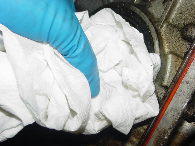
...well, almost. I've heard of people trying this method and squirting grease everywhere, so I wrapped some paper towels around the dowel to catch it.
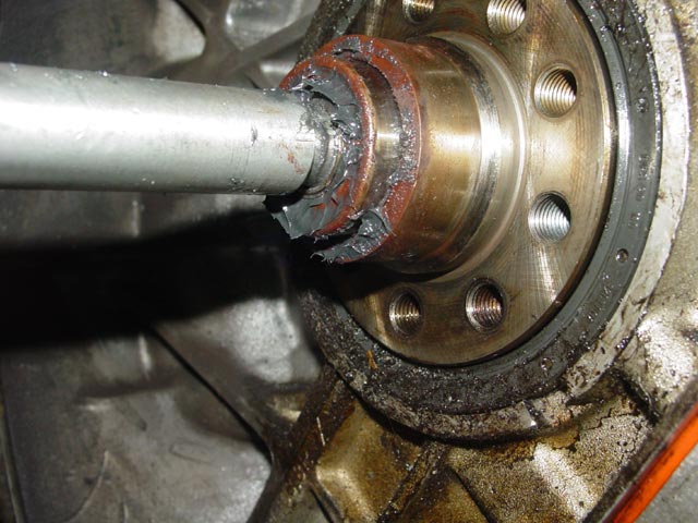
After a firm smack with a deadblow hammer, the dowel bottomed out against the crank, but the bearing moved. Note that most of the grease on the surface of the bearing got there while I was trying to get the air bubbles out.
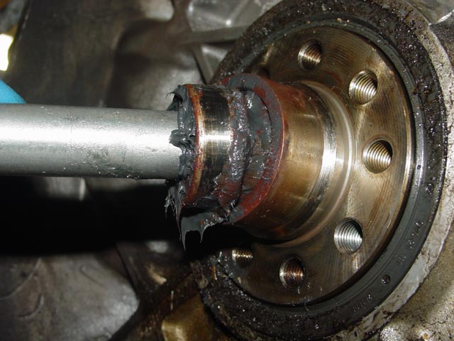
A little more grease and another smack with the hammer, and the bearing was almost out.
One more round of adding grease and smacking it, and the bearing was out.
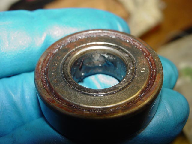
It's interesting to note that this method produces significant hydraulic force, enough to deform the metal shield on the bearing.
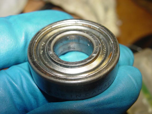
Here is the other shield for comparison. Since this is an NTN bearing made in Canada, I'm guessing it's not the original. All of the original bearings seem to be made by FAG. This bearing turned smoothly before I started messing with it, but IMHO it would be stupid to go to all this work and not replace the pilot bearing. After seeing the results, I doubt that the "hydraulic" method would work on a bearing that is shielded on only one side or on a bearing with only a rubber seal. YMMV.
I will go into detail on RMS removal(and of course, installation) on the Clutch Page.
Are we having fun yet?