On this page I document the steps that I took to refresh the clutch, and the RMS work is detailed here too since it's logically part of the clutch job IMHO. As you'll see, I went a bit "above and beyond", but if you've been reading along you should know by now that's my MO.

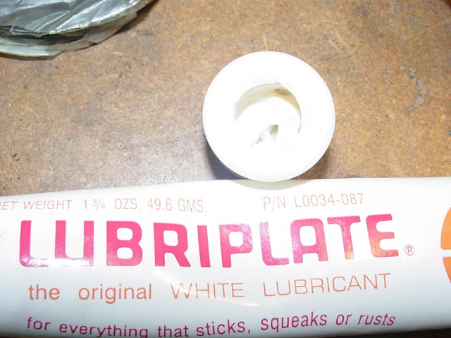
One interesting item to note: The WSM calls out three very different types of lubricant for various parts of the clutch assembly on P.30-8 and 30-9(30-11 and 30-12 for dowel-pin centered clutches, but the same recommendations apply). I followed the recommendations as you can see in the writeup that follows, except that I substituted Lubriplate for the "White Paste" recommended in the WSM.
The cross-section of the early clutch reproduced below is extracted from the WSM. There are a couple of minor inaccuracies but overall it is a good representation of how the assembly fits together and shows how the intermediate plate is centered on the flywheel lip. The inaccuracies that I've noticed are:
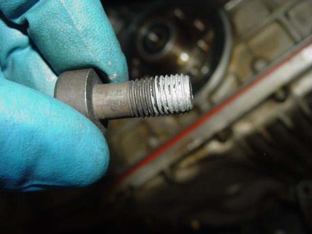
- The nut shown on the bottom bolt holding the lower bellhousing to the torque tube does not exist. The front torque tube flange is threaded and the tip of the bolt protrudes about one thread.
- The driveshaft only protrudes a couple of millimeters from the front of the torque tube, not the 25-30mm shown in the drawing.
- There is quite a bit more clearance between the guide tube and the pinch collar than what is shown here.
The A-B dimensions shown at the bottom are each called out as 17mm. "B" is the normal travel of the slave cylinder. "A" is the expected change of the initial position of the release arm over the life of the clutch. The WSM states that when the bottom edge of the release arm is at the edge of the inspection hole, the friction discs have reached the end of their life and should be replaced. OTOH, Mark Anderson at 928 International tells me that the clutch disks they have seen are usually not worn and have lots of material left on them.
I have written up a detailed Clutch Theory of Operation section near the bottom of this page to help the reader understand how to assemble and adjust the clutch.
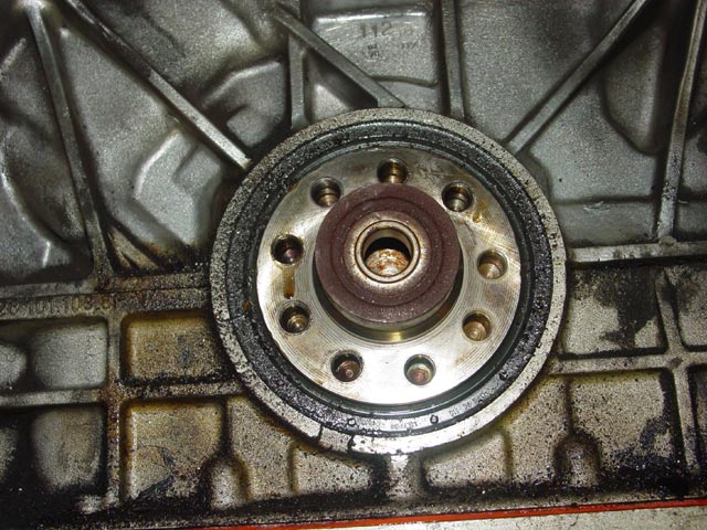
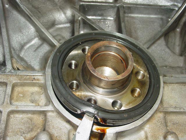
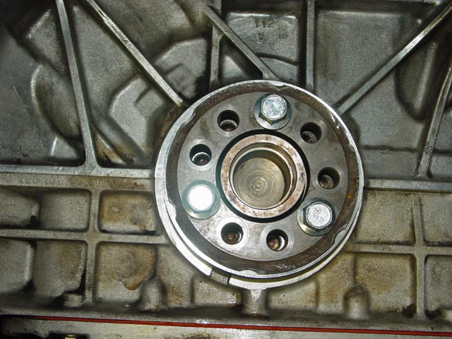
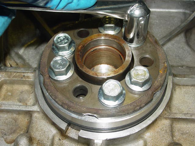
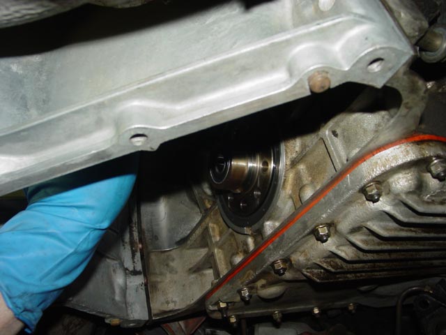
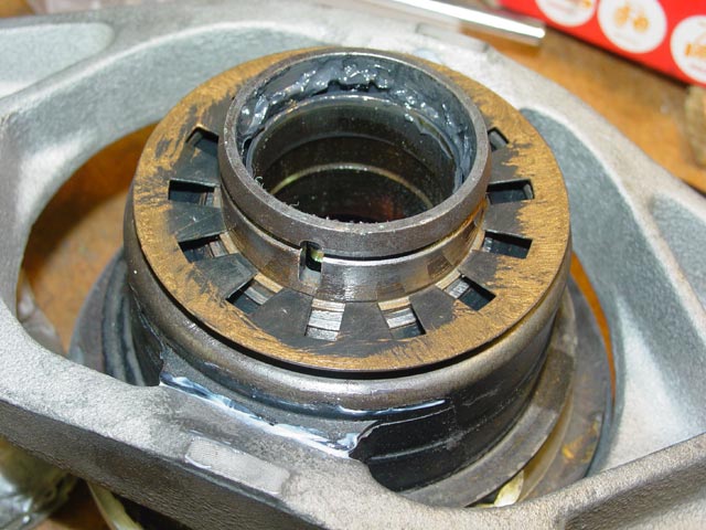
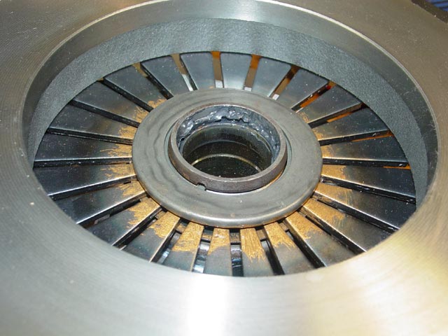
Here is how the RMS area looked when I first pulled the flywheel off. Pretty grungy. I didn't want to get any of this gunk into the area where the seal mates with the block or crank. I expected to make a mess using the "hydraulic method" of removing the pilot bearing, so I did that earlier(see the Disassembly Page, near the bottom).
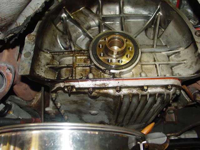
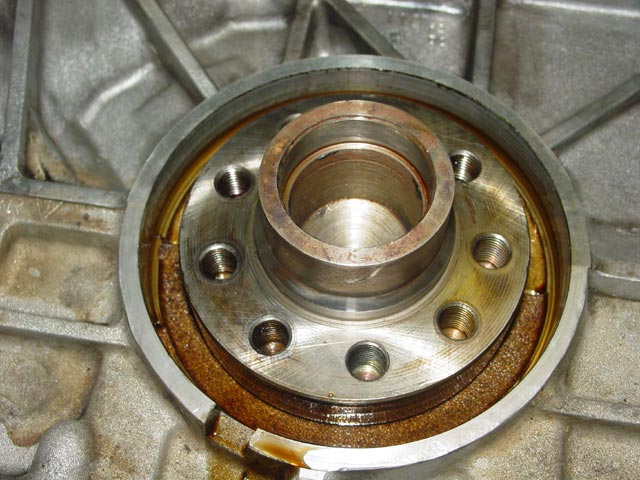
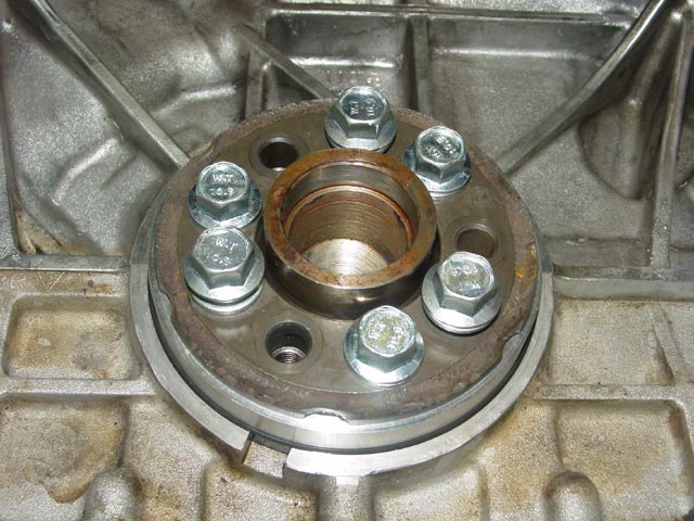
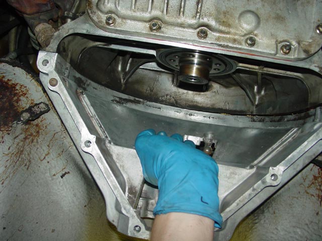
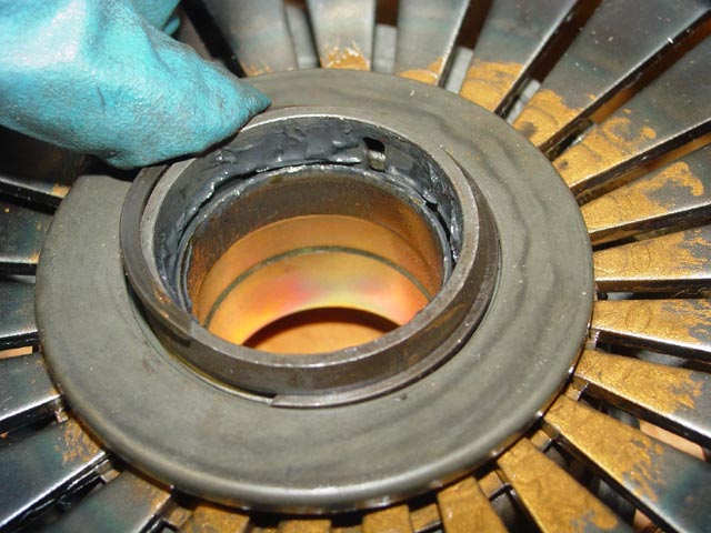
The first order of business was to clean up the mess from the old RMS leaking. I have a 7-Qt Revereware pot that I keep mineral spirits in for parts washing. I positioned that under the area I was cleaning, brushing the mineral spirits on with an old paint brush and wiping up the loosened gunk with a paper towel. In the pic below I was a bit more than half done. I wasn't looking to sterilize the area, just get it mostly clean.
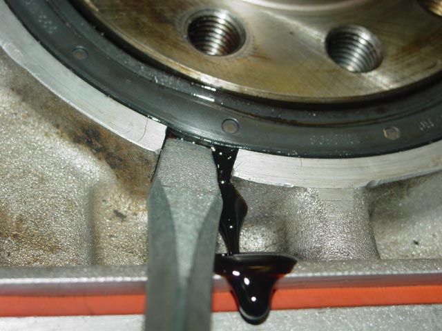
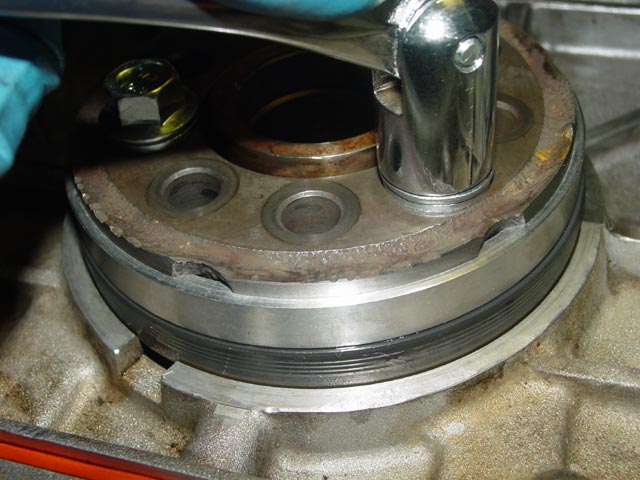
This next step is a combination of brute force and extreme delicacy. Be very careful, YOU CAN RUIN YOUR CRANKSHAFT. OK, maybe that's a bit alarmist. You are unlikely to ruin it beyond repair, but to repair a nick in the crank sealing surface properly you're probably going to have to remove the crank from the block. There are sleeves available to repair the sealing surfaces in-situ on some common domestic and imported cranks, but you don't want to go there. The seal has a cup-shaped steel core that the seal rubber is vulcanized onto. What you need to do is put a screwdriver into this groove that is provided for removing the seal and whack it just hard enough to deform the steel core a bit so you can get a grip to pry it out. You can hit it a bit harder as I did to punch through the outer rim of the steel core, but under no circumstances should the tip of the screwdriver hit the crank, either now or while prying it out.
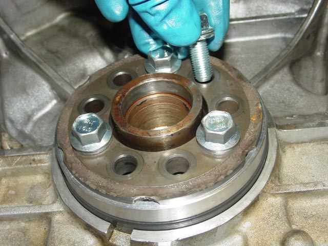
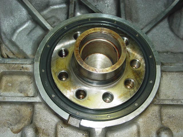
Once you have a good grip on the seal with the tip of the screwdriver, the seal just pries out. The oil that is forward of the seal doesn't circulate much, expect it to be dirtier than the oil in the crankcase.
Resist the urge to spray solvent in this area to clean it up. You don't want any sort of solvent to get into the main bearing, which is just behind this flange. Wipe the area down with a lint-free rag, and if you must use solvent spray it on the rag and wipe the area. Make sure you don't have any lint or fiber in the area where the seal installs. Double-check the area around the groove that you used to pry out the seal, it will most likely have snagged some fibers from the rag.
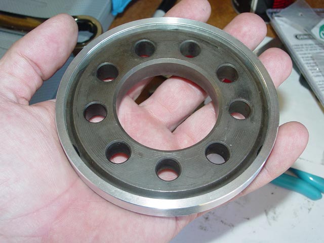
This is a press that I had machined up from the center of the old flywheel. The aluminum ring is pressed and loctited in place.
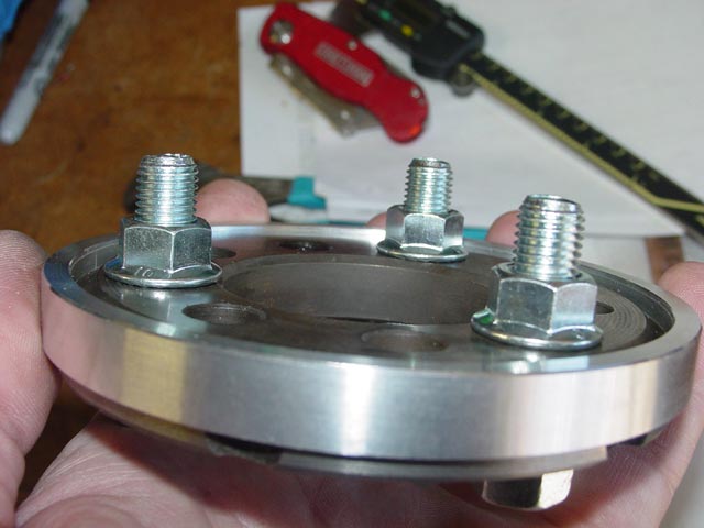
Here is a side view that shows the construction. The bolts are used to pull the seal into place, the nuts are only to keep the bolts and the press together for storage.
Here is a dimension drawing of the press. I originally had mine constructed to press the seal 0.075" forward of the flywheel mounting flange(same as original location), but I'm having it modified as shown in the drawing below so that anyone who borrows it in the future can install the seal to a different depth, for example if their crankshaft is grooved and they want the seal installed deeper so that it seals on a portion of the crank that is not worn. Now that I think about it, I may just have some additional aluminum rings made up that set the depth at 0.100" and 0.125" and forego the loctite so the rings can be swapped around.
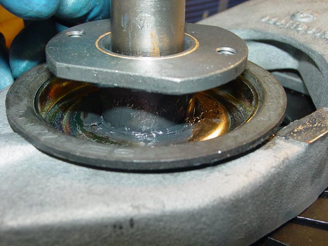
Here is the press and new seal in position. When positioning the new seal, it is essential to make sure that the lip of the seal goes over the crankshaft without "popping" over the adge of the crank. You need to work the seal ip over the edge of the crank with something benign, like the corner of a plastic scraper. If you are not careful to start the seal properly the spring that holds the seal in tension against the crank can pop off.
When setting up the press, it is important to use holes that are at the apexes of an equilateral triangle. The one hole that is offset -- the one at the 3:00 position in this pic -- should not be used because it may be more difficult to pull the seal in evenly. Before I loan this tool out I will do some color-coding to ensure that the correct holes get used. I started off with longer bolts than the stock bolts, because the original length bolts would not reach.
Here is an oblique view. The bolts are turned about 1/3 turn each at a time so the seal is pulled in evenly.
Once the first set of bolts bottoms out, a shorter set of bolts is installed...
...and the process is repeated.
When the tool bottoms out against the crankshaft, it's done!
The bolts are then removed and the RMS is ready to go.
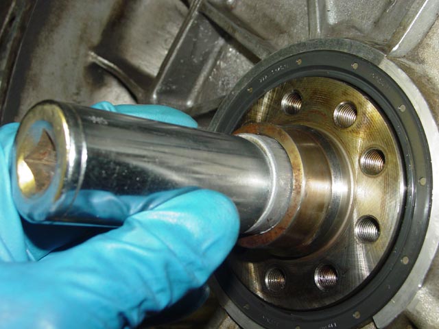
To install the pilot bearing, first I wiped a coat of anti-seize on the outside of the bearing.
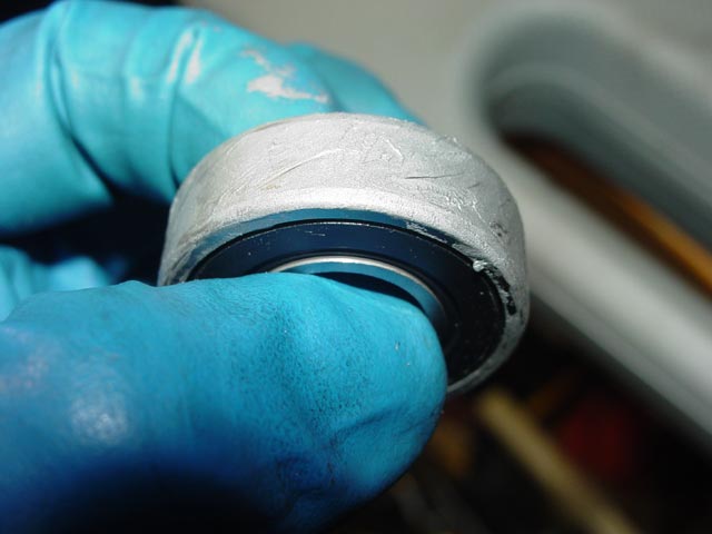
Then, using a socket that only contacts the outer race, I tapped the bearing in with a deadblow hammer. I have an aversion to hammering on bearings, especially new replacements, with any sort of metal hammer. It's probably not an issue since all of the force is going into the outer race, it's just a habit I've developed over the years. Hammering on bearings can ding the races or balls, reducing the service life of the bearing.
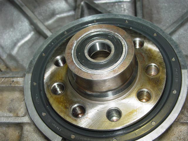
After seating the bearing, I wiped off the excess anti-seize. Ready for the next step!
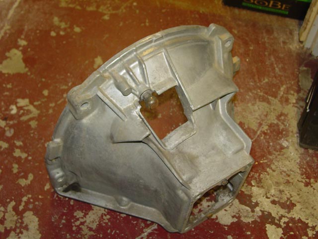
I picked up this used upper bellhousing from 928 International. It has the 19mm ball with the 8mm threads, much stronger than the old 10mm ball with 6mm threads.
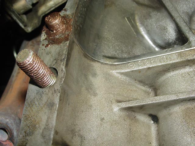
I put some copper anti-seize on the bolts and the dowel pins on the block. Copper anti-seize is preferred over graphite-based anti-seize on aluminum parts. Graphite anti-seize can promote corrosion on aluminum.
The bellhousing was lifted into position...
...and the lower bolts threaded in hand-tight to hold it in position. The guide tube mount makes a good handle.
I used my 1/2" torque wrench on the passenger side upper bolt because I couldn't get enough leverage on my shorter 3/8" torque wrench in the confined space.
I used my 3/8" torque wrench on the driver side upper bolt because there was not enough clearance in there for the head of the 1/2" torque wrench.
I used the 1/2" torque wrench on the bottom bolts because I had plenty of room and it was easier to get the required torque with the longer wrench.
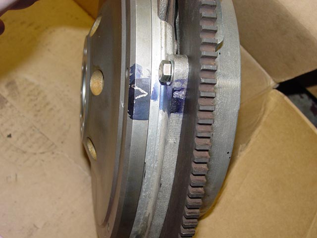
While all of this fun was going on, I had taken my used flywheel to be ground. I had picked what looked like the best one from the stack of used flywheels at 928 International while I was there. As it turned out, very little material needed to be taken off to clean it up.
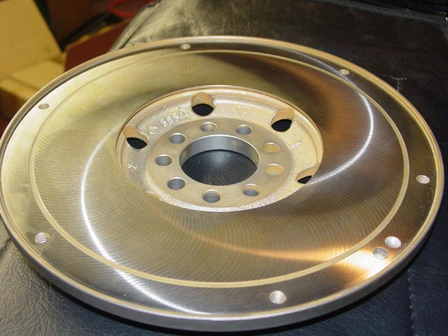
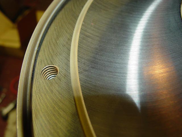
My instructions to the machinist were to take off the minimum material needed to clean up the surface, and to be especially careful that he not touch the lip around the edge that locates the intermediate plate. I told him the part would be ruined if he took any material off of there. I also explained that the relief around where the lip meets the surface of the flywheel was necessary so that the square-edged intermediate plate would clamp down flat on the flywheel surface. Any radius proud of this corner would prevent the intermediate plate from seating properly. Not knowing how much material needed to be taken off, I left him with instructions to re-cut the relief if he had to cut deep enough for this to be an issue -- but again, cut that relief without touching the lip.
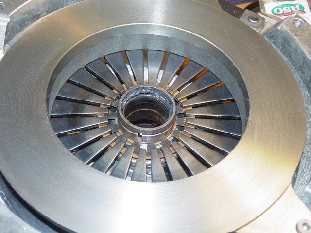
The end result was gorgeous. Almost too pretty to assemble..
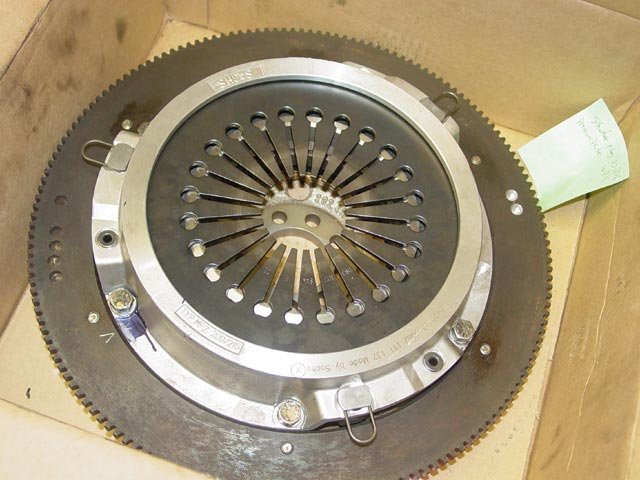
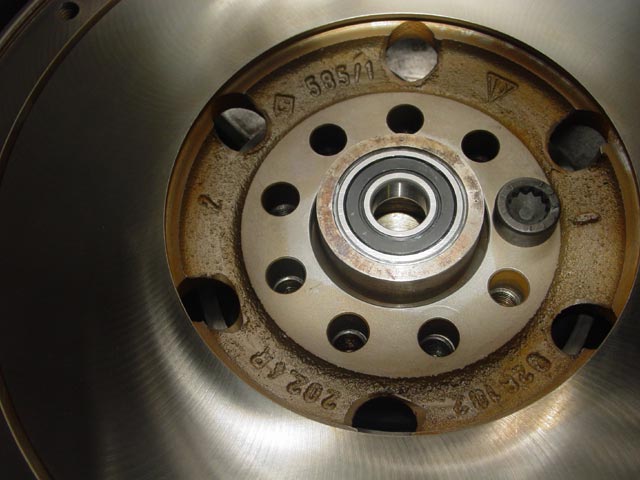
The next step was to send the clutch pack rotating assembly(minus the friction discs) out for balancing. Here it is after that process. All parts were within a gram or two(corrected within a tenth gram) except for the starter ring, which was off by 10 grams. You can see at the top right where material was removed in two places. The starter ring was torqued to the WSM spec that I gave them with blue loctite. All parts were indexed. Note the "V" marks on the starter ring and pressure plate.
The intermediate plate was also indexed to the flywheel.
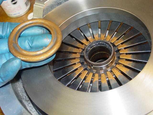
The intermediate plate was nearly new; it had been installed briefly and used just long enough for it to look used. The small amount of friction material on the plate cleaned up easily with some scotchbrite. The three intermediate plate adjusters are visible in the first pic below, just clockwise from each spring. More details at the bottom of this page.
I installed new flywheel bolts. I consider these a critical fastener that should not be re-used, I'm sure opinions may vary on that. No threadlocker is called out in the WSM so I used some anti-seize on the threads.
The flywheel only fits on the crank in one orientation. One hole is offset from the otherwise symmetrical pattern. I started the first bolt in the offset hole in the flywheel and the crank, and verified that the rest of the holes lined up. It is possible to get most of the bolts in only to find the offset hole is in the wrong location...

After getting all of the bolts in finger tight, I torqued them in a star pattern in two stages per the WSM spec: First stage to 40Nm(30ft/lb) then second stage to 90 Nm(66ft/lb).
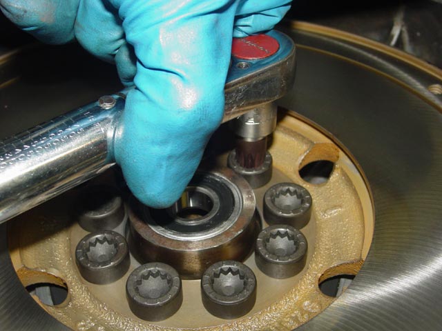
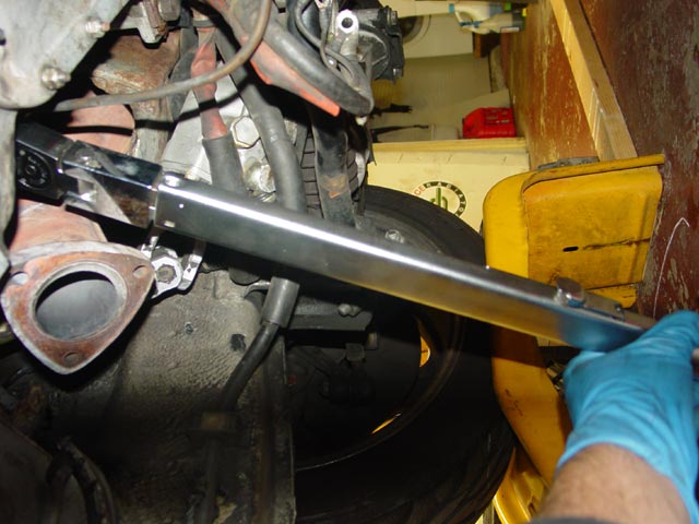
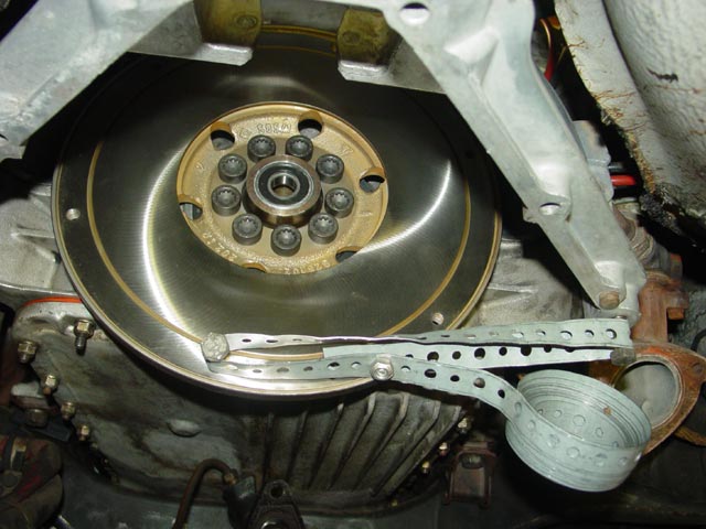
To keep the flywheel from rotating while torquing I installed a couple of lower bellhousing bolts as shown and strung a length of plumber's tape between them, held by a 6mm bolt and nut. The plumber's tape did not touch the surface of the flywheel during this process and was easily strong enough. The location of the bolt hole in the upper bellhousing angles the tape away from the surface. I installed it with as little initial slack as possible to avoid turning the engine backwards, and when finished I turned the engine forward a quarter turn from the crank bolt to ensure the timing belt was not compressing the tensioner, which could allow the engine to jump time.
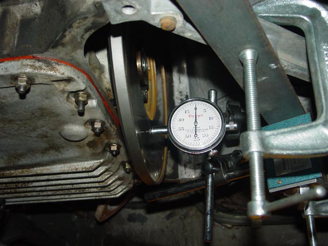
Next, I checked the flywheel runout. The pic below shows the setup with the gauge zeroed after rotating the engine a full turn. This was necessary to ensure that the main bearings were riding in their normal groove, because if the crank moved fore or aft during this check it would spoil the reading. Checked in the middle of the friction surface the runout was 0.0015", or 0.0381mm. Spec is 0.00196"(derived from 0.05mm). I took another reading at the outside edge where the intermediate plate mounts and found it to be approximately 0.00175". This was an eyeball measurement - the number I mentioned is below the resolution capability of the dial indicator.
Now it was time to lay out the clutch parts, and perform the final assembly of the clutch.
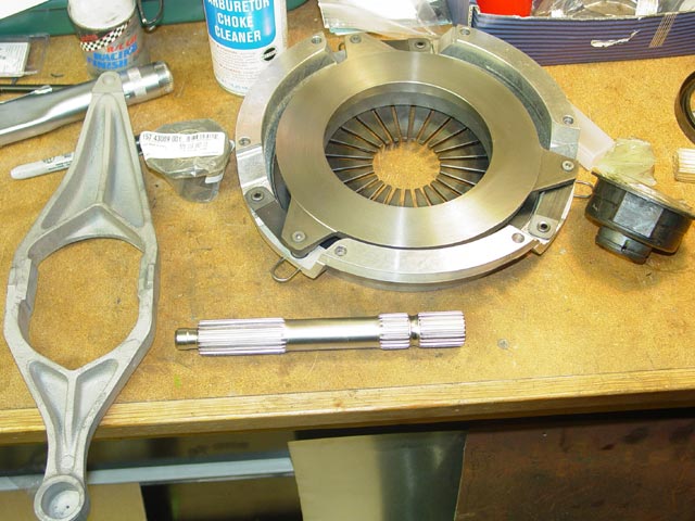
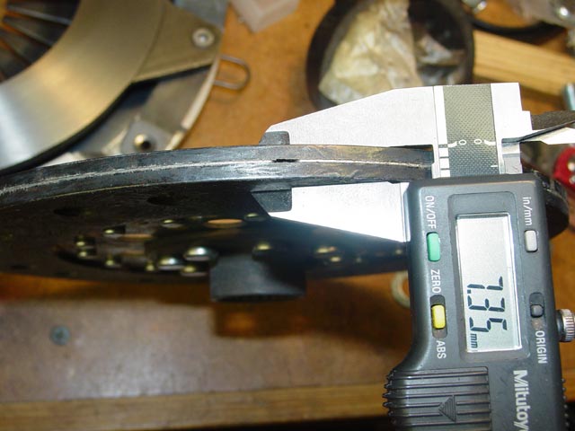
Measuring initial thickness of front disc.
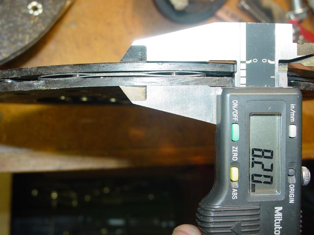
Measuring initial thickness of rear disc.
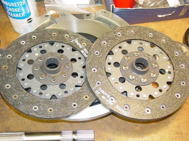
It's hard to tell the discs apart at a casual glance. The difference between the front and rear disc varies over the years. Study the workshop manual and make sure you know how to tell one disc from the other on sight before you proceed. In the case of the early clutch, the front disc has no springs between the friction discs, the rear disc does. Later front discs do have springs. See the Clutch Theory of Operation section at the bottom of this page for more details.
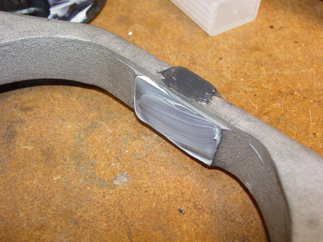
The WSM calls for "White Paste" on these rubber pads. As near as I can determine, the "White Paste" called for is a lithium grease. I used Lubriplate.
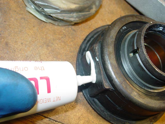
The WSM calls out a Moly grease for the contact point where the release arm bears against the throwout bearing:
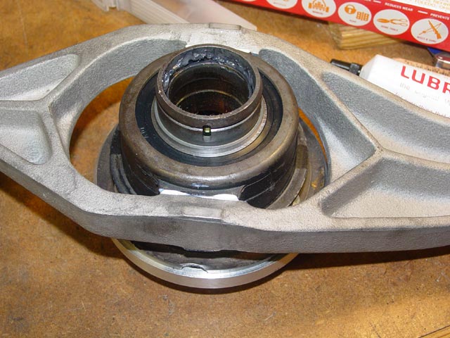
Throwout bearing positioned in release arm. I tried to use just enough grease, not so much that it would start getting onto other parts.
While I had the Lubriplate open, I greased the release arm ball cup, which also calls for "White Paste". It's important to not put too much grease in the cup or it will squirt everywhere when you snap the cup onto the ball.
The WSM calls for "Optimoly HT" on the thrust washer, pressure plate fingers, and spring washer between the throwout bearing and pressure plate fingers. This is available from the Porsche dealer under the part number 000.043.004.00 but a fellow Rennlister sent me a couple grams in a small vial. Thanks R!(I would mention his name more specifically but I don't want him to start getting a lot of requests for free Optimoly
 ). I brushed a very thin coat on the fingers.
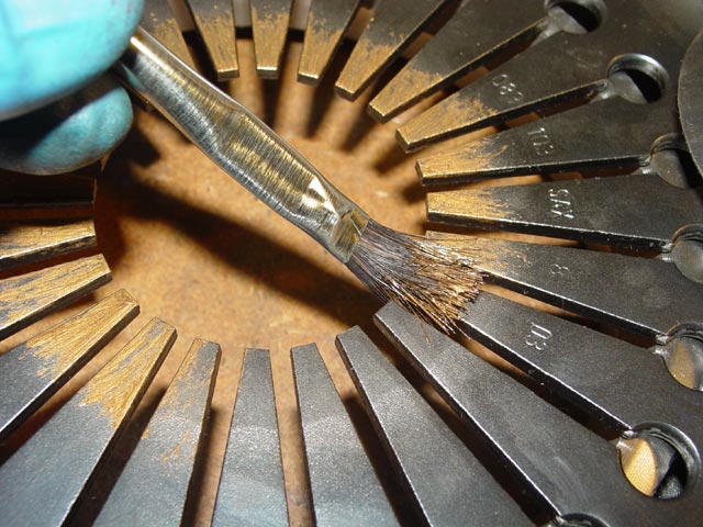
I also brushed a thin coat on the spring washer, both where it contacts the throwout bearing and where it contacts the pressure plate. The WSM isn't especially specific on this -- it just says apply Optimoly to the part.
Next, the pressure plate is positioned over the throwout bearing and spring washer.
The pressure plate fingers and thrust washer each get a thin coat of Optimoly. Note the little anti-rotation tab just above my ring finger. This tab engages with the slot visible in the throwout bearing. Be very careful to avoid getting any lube into either the circlip groove in the throwout bearing or the circlip groove in the back side of the thrust washer.
Thrust washer in position. Note that at this stage, it will not be possible to install the circlip that retains the thrust washer. The pressure plate will have to be compressed.
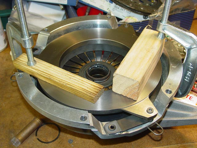
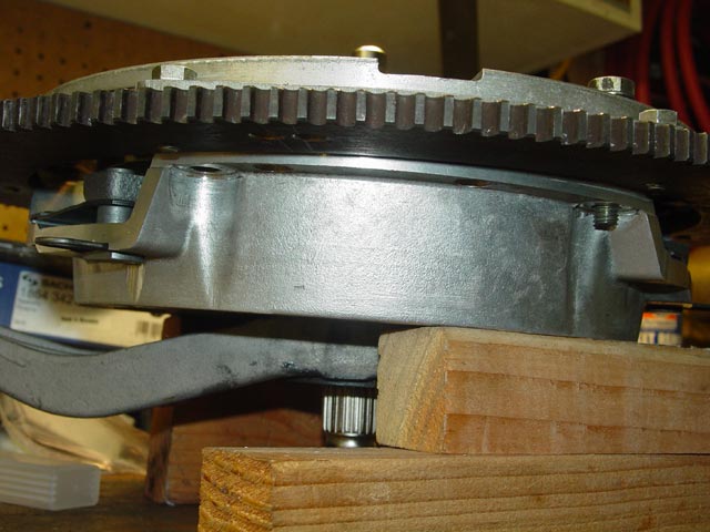
It's fairly easy to compress the pressure plate with some C-clamps if you do not have a press as shown in the WSM. I used wood blocks to avoid marring the pressure plate surface.
Now would be a good time to pull out the assembly shims and shorten them. I did not do so and the shims interfered with the bellhousing as I rotated the crank to get all of the clutch mounting bolts tight.
With the pressure plate compressed the circlip can be installed. As mentioned above, it's very important that it be installed dry. There is a bit of lube on the circlip in this pic, I wiped it off before fully engaging the circlip. Too much fumbling with the camera... Also, it's critical that the circlip be installed so that the open end is 180� away from the groove for the thrust washer tab in the throwout bearing. Once the circlip is installed the c-clamps can be removed from the pressure plate. Be sure the assembly shims are in place as you release the c-clamps!
New friction discs have a yellow paint dot indicating the "heavy" side, determined by the manufacturer upon assembly and balance checking. The paint dots are conveniently located on the back side where you can't see them while assembling the clutch.
 I transferred the marks to the front side of each disc with a sharpie.
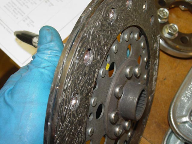
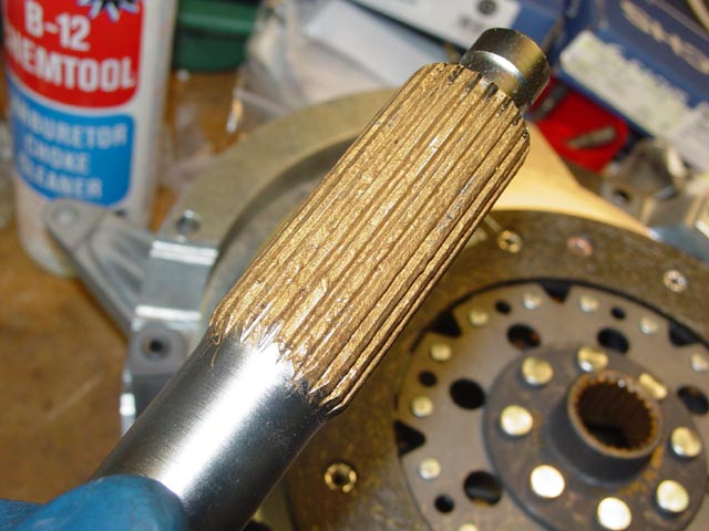
I put a thin coat of Optimoly on the splines of each disc.
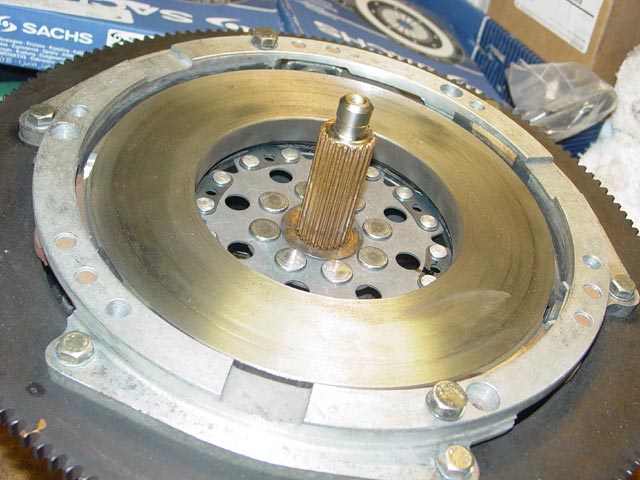
I propped the pressure plate up on some wood blocks to position the stub shaft in approximately the right location for assembly.
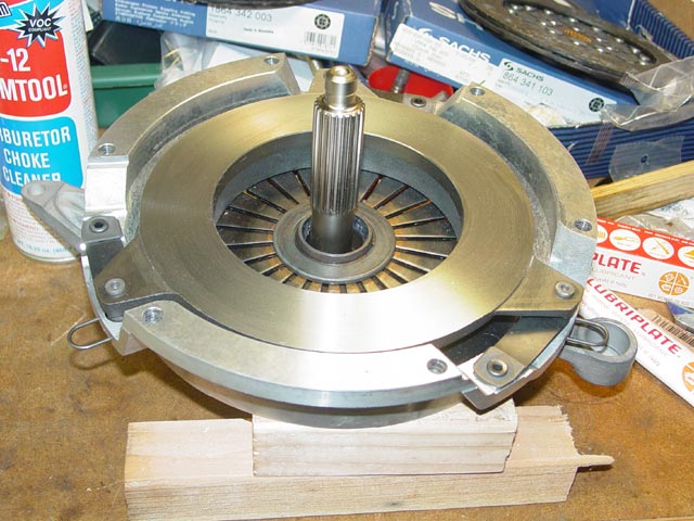
I then put a thin coat of Optimoly on the stub shaft splines, placed it back in the throwout bearing, and slipped the rear disc over the shaft.
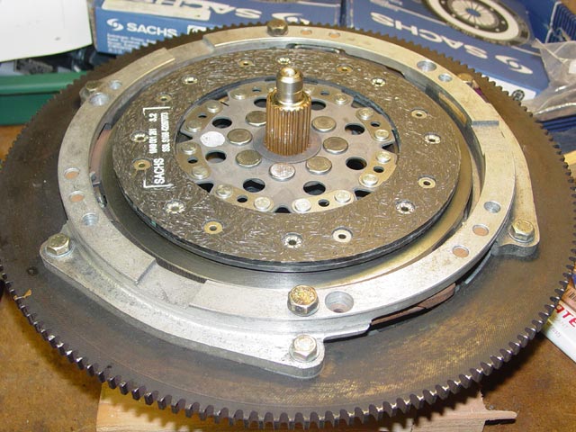
The next step was to lay the intermediate plate in place, lining up the index marks(not shown in the pic below). The pressure plate is a close fit inside the starter ring. I placed a couple of bolts through the intermediate plate and pressure plate just to keep them located with one another.
Back to the top view -- you can see the sharpie mark(aligned with the yellow paint dot) at about the 4:00 position on the rear disc.
Finally, the front disc is laid in place. The sharpie mark(aligned with the yellow paint dot) on this plate is visible at about the 11:00 position. The marks were in fact lined up 180� from each other; it may not look like it because of the different camera angles though.
With the clutch pack assembled, I put a very thin coat of Optimoly on the end of the stub shaft that goes into the pilot bearing. I also moved the stub shaft back and forth, making sure that I did not have excessive Optimoly on the splines that might squeeze out and make its way onto the friction surfaces.
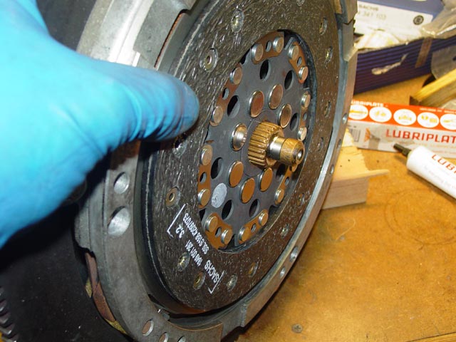
I put the stub shaft in approximately the position it would be in when assembled.
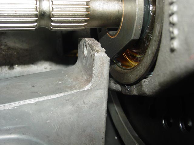
Next up, I installed the guide tube with a generous(but not too generous) glop of moly grease per the WSM, working the guide tube in, out, and around to make sure the grease was well distributed.
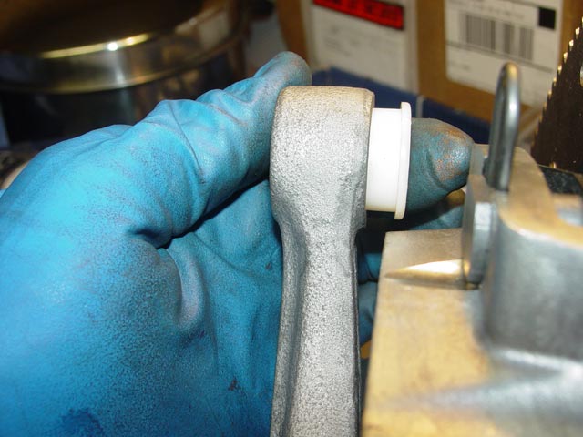
Finally I inserted the pre-greased plastic ball cup bushing in the release arm.
After making sure that all grease was removed from my gloves and that none had found its way onto the front disc or the flywheel, I lifted the clutch pack into place and started a couple of the bolts that hold it to the flywheel. Make sure the guide tube is forward of the guide tube mount, and don't allow the lubed end of the stub shaft or the lubed ball cup bushing to contact the friction surface of the flywheel. Time for a beer!
While hanging the clutch pack I made a point of positioning the ball cup bushing over the ball. It's a bit of a hassle getting the clutch pack in place, since you have to watch 3 or 4 things at once. Not too bad though, you just have to pay attention and be patient.
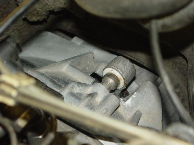
I reached down with a prybar to snap the ball cup over the ball.
Done, and it seems I put just about the right amount of grease in the cup. I reached down with a rag on the end of a screwdriver and wiped up the excess.
At this point, the clutch pack is in and torqued to spec, guide tube bolts are torqued to spec.
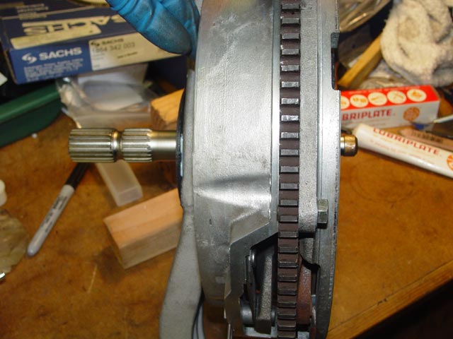
I wire-brushed the rust from between the teeth on the starter ring and would later put a thin coat of Optimoly on the teeth per the WSM(not now, I didn't want to get the stuff all over me). Also visible in this pic is the intermediate plate adjuster. Using a prybar between the top ridge of the pressure plate and the end of the release arm, I released the clutch and pushed the adjuster all the way back. When the clutch was re-engaged it pushed the adjuster slightly forward. I turned the crank at the front crank bolt and repeated the adjustment on the other two adjusters.
At this point there was not much to do but wait for the transaxle and the torque tube bearing carriers from Constantine. I suppose I could have cleaned up the shift linkage, but I decided to wait.
Clutch Theory of Operation:
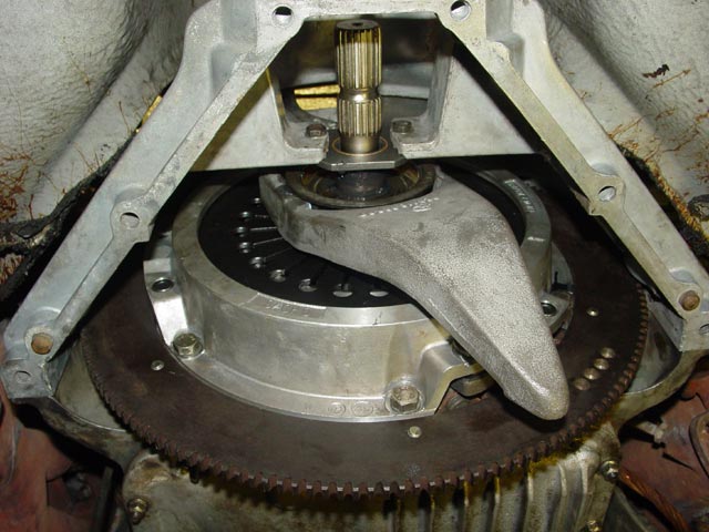
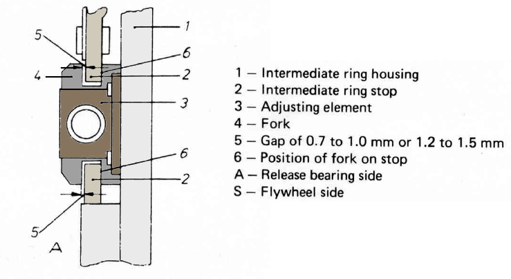
This is the diagram in the WSM for adjusting the intermediate plate. The right side in the diagram is forward. The "fork", #4 in the drawing below, is the white metal piece just visible to the left of the starter ring and to the right of the gray casting(pressure plate) in the center of the above pic. The "adjusting element", #3 in the diagram below, is the sort of rust-colored piece in the center of the "fork". It is actually the fork(#4) that moves fore/aft on the adjusting element(#3) when setting the adjustment. The point #6 in the diagram below is where the adjuster was pushed forward when I engaged the clutch. As the front disc wears, the fork will continue to move forward due to contact at this point. Note that the smaller gap specified is for early clutches, the wider gap specified is for later clutches. Be sure you understand the discussion of this gap as it relates to clutch release below.
I've done plenty of clutches on different cars, all of them basically the same with the only difference being some design details of the release arm and throwout bearing assemblies. I should mention, before I touched my 928 clutch for the first time going on 5 years ago I read everything there was to read about it, scrutinized threads and pics, and so on. And I later realized that I never fully understood how the effing thing was supposed to work. The lightbulb finally went on when I moved the release arm with a prybar, watching the adjusting forks on the intermediate plate as I engaged and disengaged the clutch. Really, take a few minutes and do the same. Crawl under there and watch the forks as you operate the clutch. Then watch it from a different angle, and move the light around. Watch the disks as you operate the clutch. IMHO the only way to really understand how it works is to watch it in operation.
I can help the reader along a bit though. In the diagram below, the blue part is the pressure plate. The green part is the intermediate plate. The red parts are the friction pads on the disks. I have flipped the diagram horizontally so that its orientation matches the orientation of the adjuster fork image above, and all numeric references are to the diagram above. This makes certain concepts clearer. For example, the housing(1) is bolted firmly to the flywheel and does not move. The stop(2) is part of the intermediate ring and floats(with a light spring-loaded bias toward the rear) within the range allowed by the fork(4). The gap(5) in the image above closes down and a gap opens at location(6) as the slave cylinder pushes the bottom of the release arm to the left and the intermediate plate follows the pressure plate rearward.
When the clutch is disengaged(slave cylinder extends), the blue pressure plate moves rearward. The green intermediate plate has springs on it, which move it backwards as well. It follows the pressure plate until it catches on the forks, meaning gap(5) is zero. This gap is critical, because it determines how much the intermediate plate moves rearward to release the front disc. At this point, the intermediate plate stops moving rearward, but the pressure plate continues to move rearward until the clutch pedal is on the floor. Ideally the adjusters should be set so that the gap between the rear friction disk and the plates is about equal to the gap between the front friction disk and the plate/flywheel.
The intermediate plate needs to move back 1mm to 1.5mm(gap(5)) before it catches the fork, stopping the intermediate plate's rearward motion. This allows room for the front friction disk to spin freely. Then the pressure plate needs to continue to move backward another 1mm to 1.5mm. This allows room for the rear friction disk to spin freely. If this gap(5) is too small, the front disk will not have enough room to release completely, since the intermediate plate will not move far enough to the rear. If this gap is too large, the intermediate plate will move too far to the rear and will bind the rear disc against the pressure plate. Having too much or too little gap will result in a dragging clutch. However, the adjusting fork(4) wears over time, and in this case the absolute measurement of the gap is less important than the fact that it must be positioned so that both the front and rear friction discs have enough room to spin free with the clutch released.
Re-read the above paragraph carefully. This is the most critical aspect of adjusting the clutch.
The slave cylinder and the bottom of the release arm moves ~17mm with full clutch travel, no air in the system, no ballooning of the clutch hose. While adjusting the clutch it is important to only move the release arm 17mm or so to estimate the clearance between clutch disks and plates. A bit of quick geometry would indicate that with the slave moving 17mm the throwout bearing ought to move about 8.5mm, and I have only accounted for (2 X 1.5mm) or about 3mm. One clutch disc has springs between the friction surfaces and it collapses about ~1mm when the pressure plate presses against it. The remaining ~4mm is required to take the preload off of the pressure plate, so you can see there is little margin for error.
The closer you are to simulating the 17mm stroke length of the slave cylinder while adjusting, the better you will be able to set the intermediate plate to the proper mid position between the flywheel and the pressure plate. You can control the amount of movement by using a prybar where I've drawn the purple line. If you move the arm too far while adjusting, you may set the intermediate plate too far to the rear in your attempts to center it. Then, when it's only moving 17mm under the influence of the slave cylinder, there won't be enough clearance between the intermediate plate and the pressure plate.
It's pressure from the spring inside the slave cylinder that normally keeps the release arm from flopping around. If the ball cup bushing is shot, that spring is extended more and doesn't hold the release arm in stable tension anymore. This can cause a rattling that goes away with light pressure on the clutch pedal. A broken spring inside the slave cylinder can cause similar symptoms.
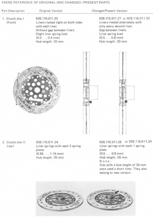
Below is a section from the WSM that shows differences in clutch discs. Note that the .33 and .34 numbers cannot be found in PET, 84-86 part numbers are .35 and .36(F/R respectively). That gives us the following numbers:
Front:
928.116.011.23: 78-79+
928.116.011.27: 80+
928.116.011.33(35): 84-86
Rear:
928.116.011.24: 78-79+
928.116.011.28: 80+
928.116.011.34(36): 84-86
Additionally, here is an excellent video from Dan Perez(that's his Rennlist ID) that shows the two-stage release of first the intermediate plate(small, bright rectangle just forward of the starter ring and aft of the center bolt on the oil pan) then the pressure plate.
6/29/2009:
After having a long discussion with Mark Kibort here about clutch adjustment, I am updating this page with some photos and discussion regarding the question of whether the forks(AKA "H" adjusters) wear or not. Most of his confusion about what the minimum allowable gap should be would have been cleared up had he read the above section, especially regarding the release sequence of events and the springs in the front disk. Because the front disk may expand up to 0.8mm, his recommendation to set the gap as small as 0.75mm would not allow the clutch to release in some cases.
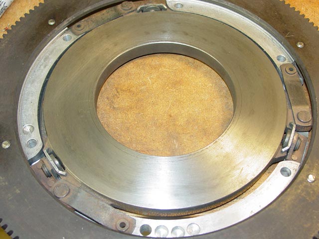
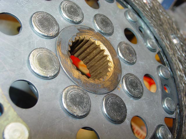
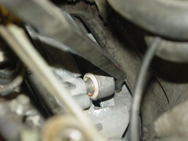
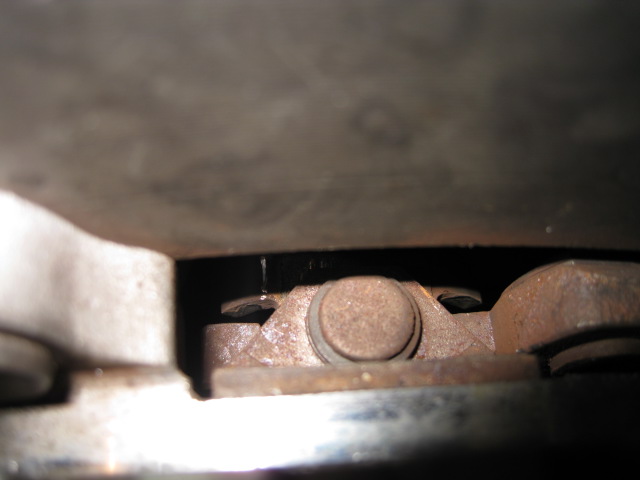
One point that seems especially difficult to get across is that the forks do in fact wear; Mark is as of this writing convinced that they do not. He has often mentioned that on his worn, spare plate from a '79 car, he sees a max gap(5 in line drawing above) of nearly 1.5mm, where I have observed the gap on a new plate to be more like 1.2mm. He has on occasion compared his to a later version of the plate, which starts off with a max gap(5) of about 1.5mm. I think that this apples and oranges comparison has misled Mark, since AFAIK he has never measured a new plate. The picture below, provided by Mark Kibort, illustrates that on his plate, there is a relatively large contact area where the fork contacts the intermediate plate when the clutch is released:
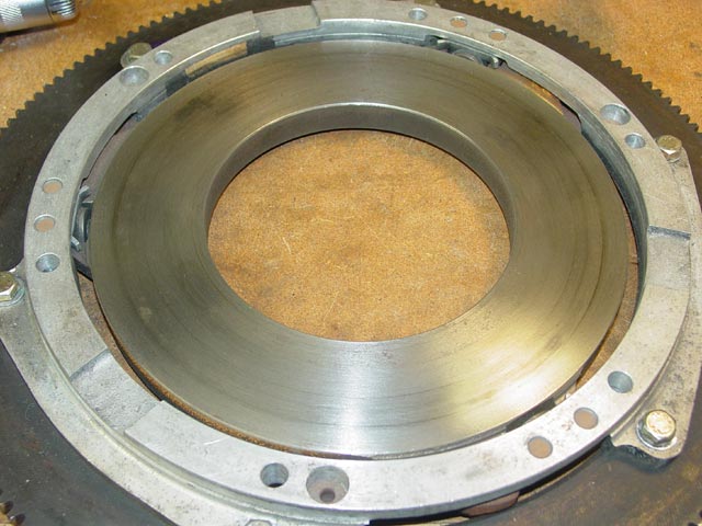
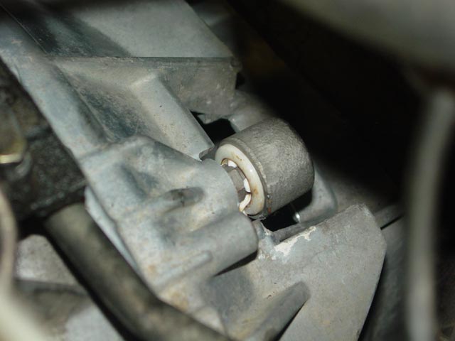
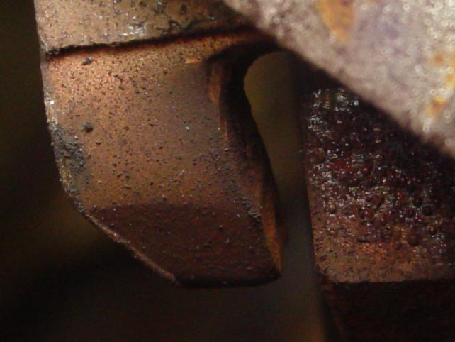
Here for comparison is a picture of the same feature on the intermediate plate that I pulled from my '78. Of particular interest here is the much smaller contact area. You can see that over much of the surface of the fork, there has been no contact with the intermediate plate. This is because on a new plate, a new fork starts off only making contact in a small area due to the relief angle that is formed as part of the fork. As the fork wears, the contact area increases as the fork wears and the contact area creeps up along this angled feature.
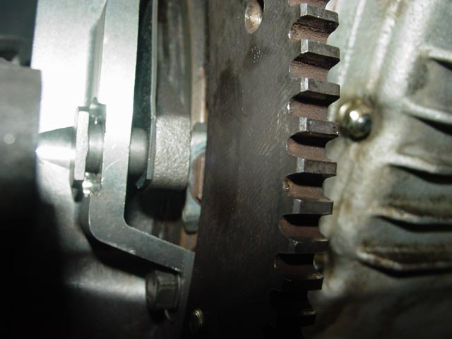
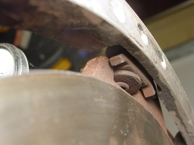
Here is an example of wear on the opposite side of the fork due to contact with the intermediate plate, which occurs as the front disk wears and the intermediate plate pushes the fork forward. The purpose of this feature, and the reason for pushing the fork forward as the front disk wears, is to keep the gap(5) from widening too much as the clutch wears. If this self-adjustment were not built-in, the clutch would begin to feel sloppy over time, as an increase in gap(5) will result in the rear disk disengaging later and later as the front disk wears. The wear is slight, but it is present. It is visible as a slightly discolored, smooth spot in the gap between the fork and the intermediate plate. I point this out because Mark made the statement that this side of the fork never wears.
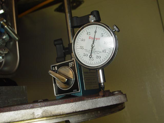
Finally, here is my measurement of the gap on a slightly worn fork/intermediate plate. The mag base for the indicator was mounted to the steel friction plate, and the tip of the indicator was zeroed on the top of the fork.
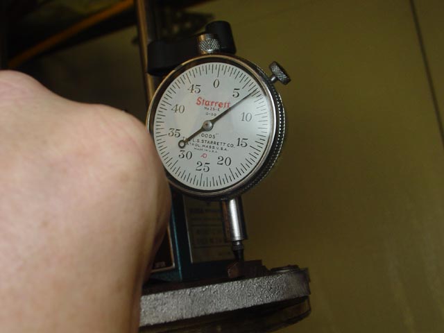
Here I have deflected the intermediate plate until it contacted the fork, closing gap(5). Total movement was 0.057" or about 1.45mm. The new intermediate plate gap was measured at 0.046" or about 1.168mm(call it 1.2mm) so here we have a difference of 0.2mm which is consistent with the observed wear.
In conclusion, it is clear that the forks do in fact wear over time, as the photographs above and my own measurements prove. If anyone would care to offer additional data to support either the assertion that they do wear or they do not wear I will gladly consider it and, if the measurement methods are valid and repeatable I will post the details here.