While this page is titled "Analysis" I don't mean to imply that I am offering an exhaustive, professional engineering analysis. What I mean to do here is share some observations regarding issues I uncovered while refreshing my drivetrain and some limited analysis based on decades of experience working on cars, robots, and a wide variety of other machinery.
To begin, my initial speculations as to what was wrong with the car are on the drivetrain intro page. There were a few surprises as well, some of which explain behavior that I thought was normal or was caused by other issues.

A couple of snippets of information also appear elsewhere in this drivetrain section but I wanted to have all of this info aggregated on one page. Where info is duplicated in other sections it is because the info is illustrative in the context of the page in which it appears.
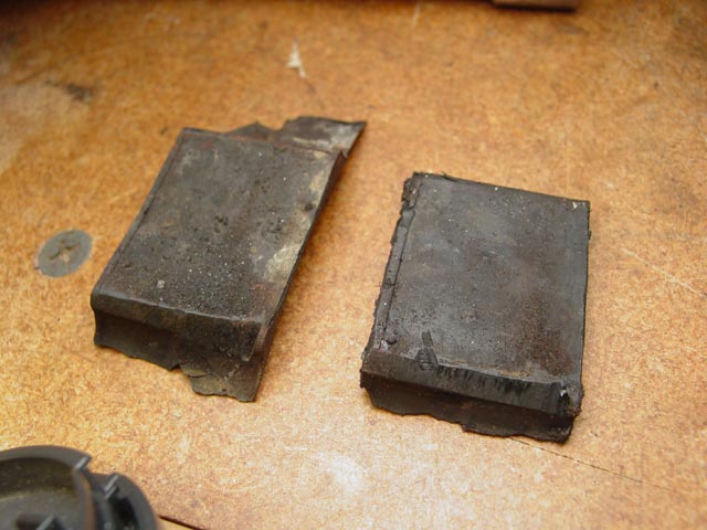
When I first dropped the lower bellhousing, I found the piece of plastic below. This is a good example of duplication -- it is always important to look at things as you take them apart, instead of wondering later where some odd piece came from.
I didn't know where it came from at first, but then I looked at the replacement throwout bearing and had my answer. This piece is one of the "pads" on the side of the throwout bearing. One of the things that confused me at first is I couldn't see enough clearance for this pad between the bearing and the release arm. It turns out, there is not enough clearance for this on the original release arm.

I dug into the WSMs and found on page 30-20(1982 update) that my release arm with the small ball stud and narrow opening for the throwout bearing, should have been replaced along with the bearing. The original bearing and release arm were superseded and the correct throwout bearing would have been NLA. The fact that the release arm was not updated indicates that someone dropped the ball. Due to time or budget constraints, or just plain ignorance, the mechanic ignored the fact that the parts did not fit together properly. Below is an excerpt from page 30-20 of the WSM that describes the issue.
I suppose it's possible that the mechanic did get his hands on the correct release arm but was unaware of the fact that the larger 19mm ball was available to retrofit early bellhousings that had the 6mm thread. He may have looked at the replacement release arm, maybe even looked at the later replacement ball with the 8mm threads and decided it couldn't be made to work without re-tapping the bellhousing, and gave up. It's interesting to speculate on but I'll never know. Bottom line is, it's my mess to clean up now. When I first adjusted the intermediate plate to get the clutch to release properly I should have taken it all apart and inspected it, but since it worked I left well enough alone.
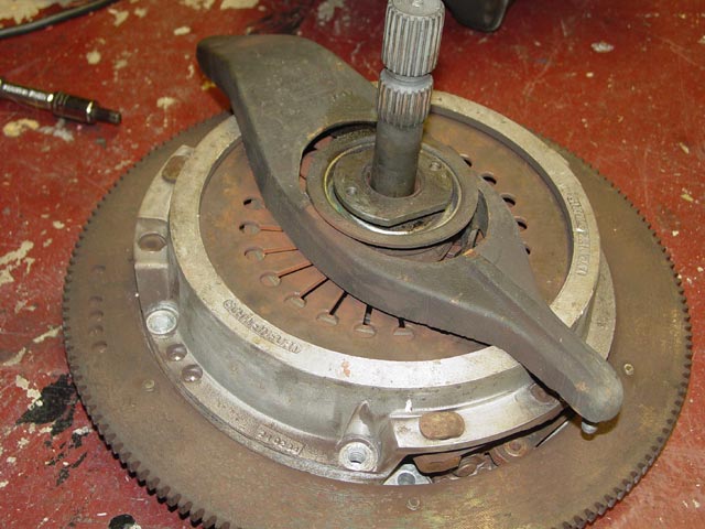
After I had everything apart, I found the other piece. It had been wedged against the release arm. You can tell by looking at the pieces that they were cocked in the too-narrow release arm, which would have prevented the arm from sliding properly against the throwout bearing as the clutch was engaged and disengaged, creating a side load on the ball stud.
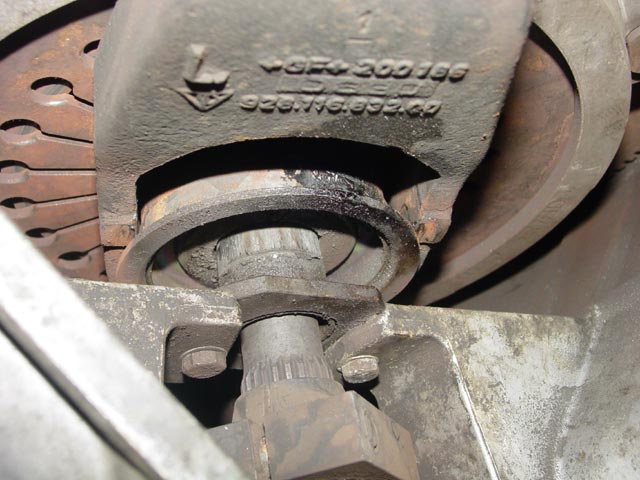
Here is the end result of that side loading. As the release arm rotated rearward(diagram), the friction of the cocked throwout bearing against the release arm would have pushed the throwout bearing up toward the ball stud until it bound against the guide tube. As the release arm continued through its arc, unable to move upward because of the binding of the throwout bearing against the guide tube, it would have put considerable downward force on the ball stud with each actuation, with the eventual result that you see below. I'm pretty sure the throwout bearing was never intended to have much side load on it, and this may have caused it to fail earlier than it would have had it been installed with the correct release arm.
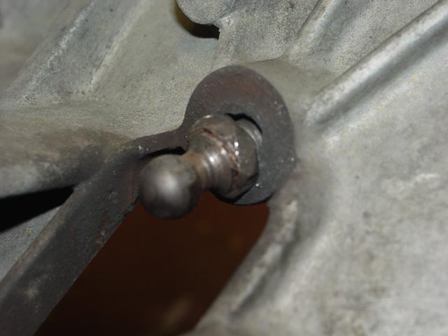
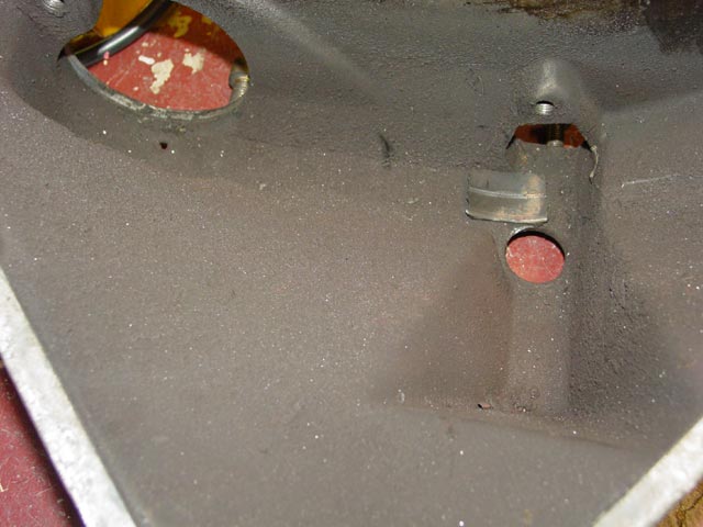
Here is the wear on the ball stud boss. You can see that it was cocked quite a bit.
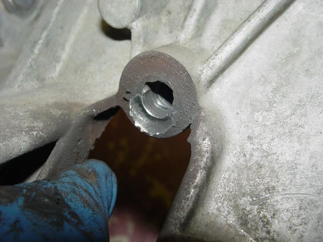
Another view of the hole, showing how the end of the ball stud dug into the wall of the hole.
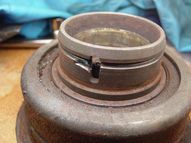
Whatever grease was used when this was last assembled, it was just about worthless. You can see here where it dripped down from the guide tube, over the lip of the throwout bearing, and down the release arm.
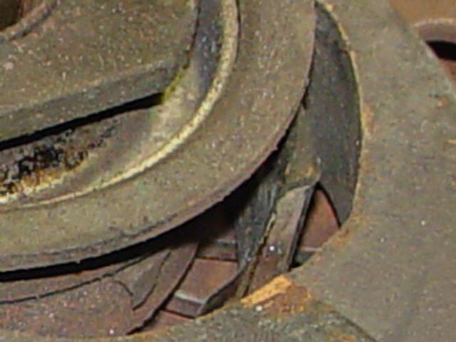
You can see in this pic too, where the grease ran down and away from the guide tube. You can see the rubber pad wedged in the gap between the release arm and the throwout bearing.
Here's a closer look at that rubber pad. It was obviously only held in by virtue of being wedged in place, and would have vibrated out as the other piece did if not for gravity. IMHO this piece being wedged in there is the only reason the throwout bearing did not spin against the release arm and guide tube when it seized.
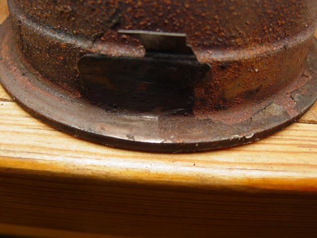
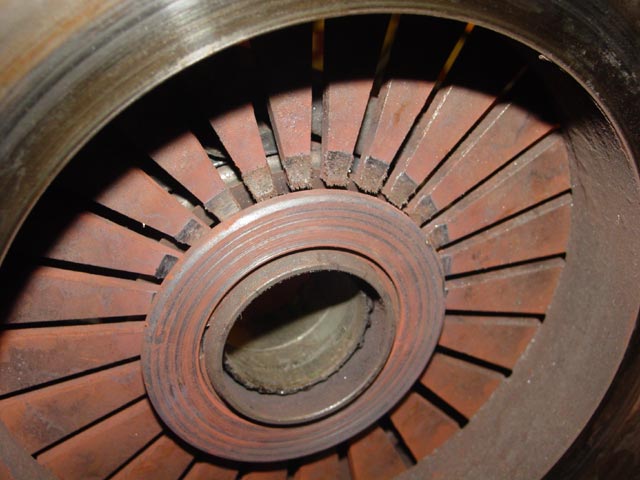
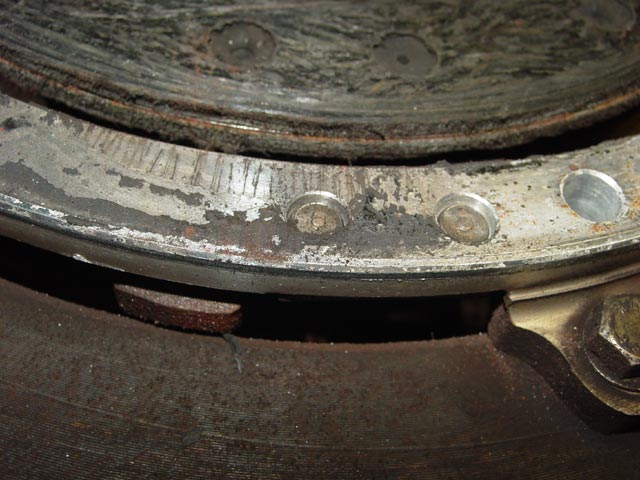
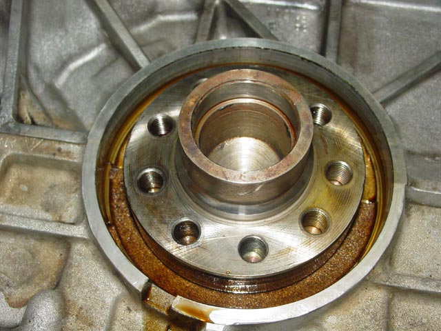
The evidence of side loading on the bottom of the guide tube is very obvious. The opposite side is hardly worn at all.
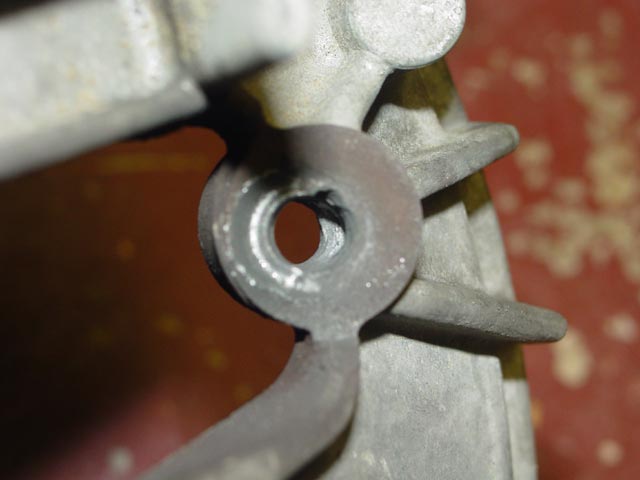
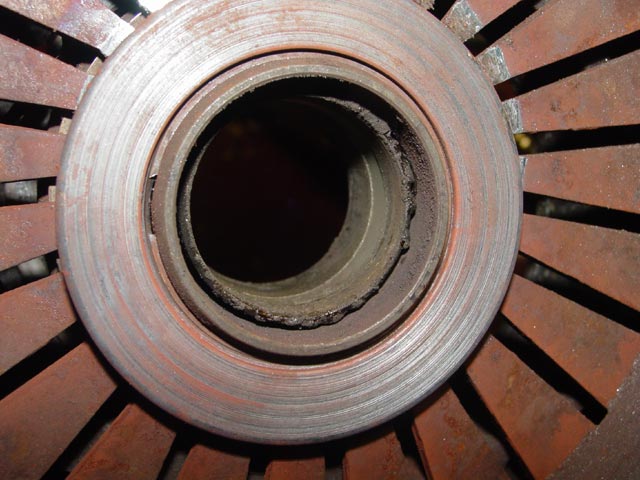
I figure that most of this damage around the circlip groove happened after the throwout bearing seized, due to the locating tab on the thrust washer vibrating against the slot in the throwout bearing. I'm glad I caught it when I did... To see what the tab on the thrust washer looks like, see the clutch page which has a good pic of a new thrust washer.
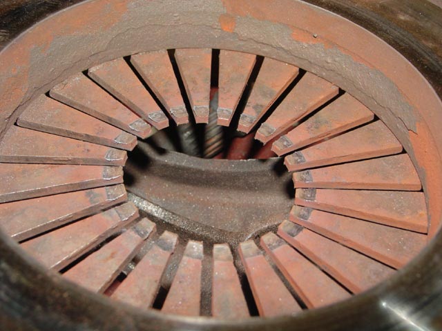
Here you can see where the release arm contacted the throwout bearing when the clutch was actuated, and where a small portion of one rubber pad was wedged between the release arm and the bearing housing.
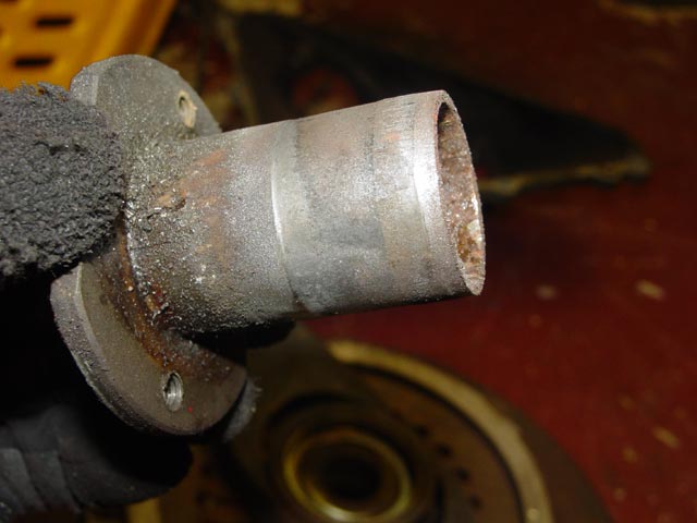
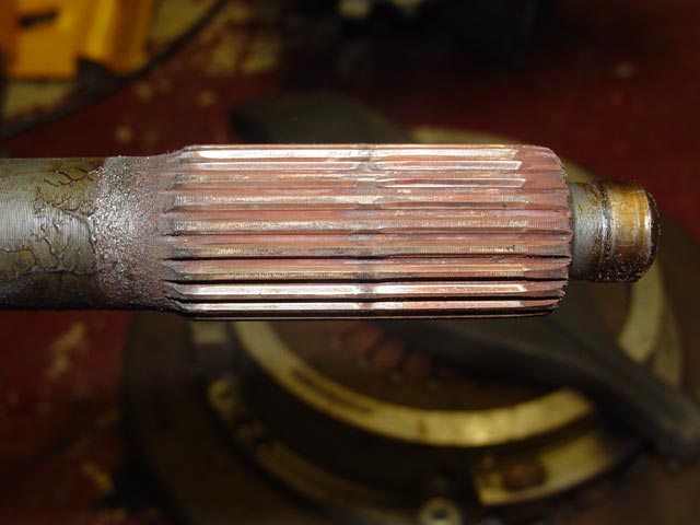
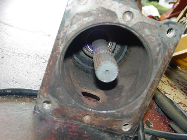
The grease that had been applied to the stub shaft had turned to a hard varnish where it still remained(far left and far right of pic) but appeared to be completely absent on the splines themselves, with rust evident on all areas that were not in regular contact. This picture makes an excellent case for replacing the stub shaft when replacing clutch disks. The wear that can be seen on the right hand side(from the front disk) is harmless enough when the splines on the clutch disk are similarly worn. As bad as these splines look, my clutch was releasing fine. IMHO the problems arise when new clutch disks are installed on a worn stub shaft. What happens in that case is that the new spline, which has straight edges, catches on the worn groove, and the worn groove effectively acts as a ramp which the female spline cannot climb out of, preventing the plate from releasing properly.
Here you can see how dried out the throwout bearing was. those little blobs of grease appear to be fossilized. Why the grease would dry out on a part that is greased from the factory and cannot be serviced is a mystery to me. Seems I ought to check this out on a regular basis, probably 25-30K mile intervals.
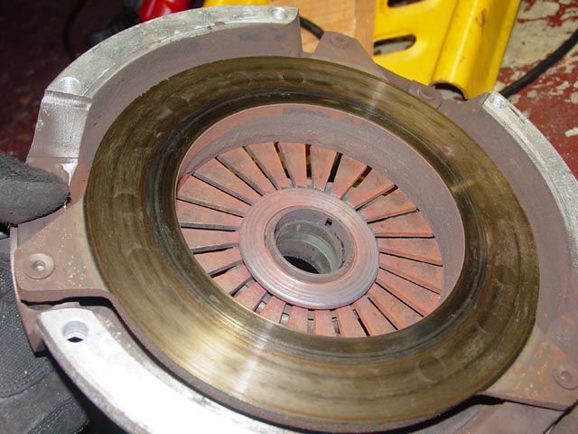
These next two pics show the wear on the pressure plate fingers due to the throwout bearing seizure.
The pressure plate didn't look too bad. I'm not sure why it seems to have heated up more in the center. Even if the fingers were not worn, I was planning to replace it, since I had had it slip on one occasion due to a hard launch.
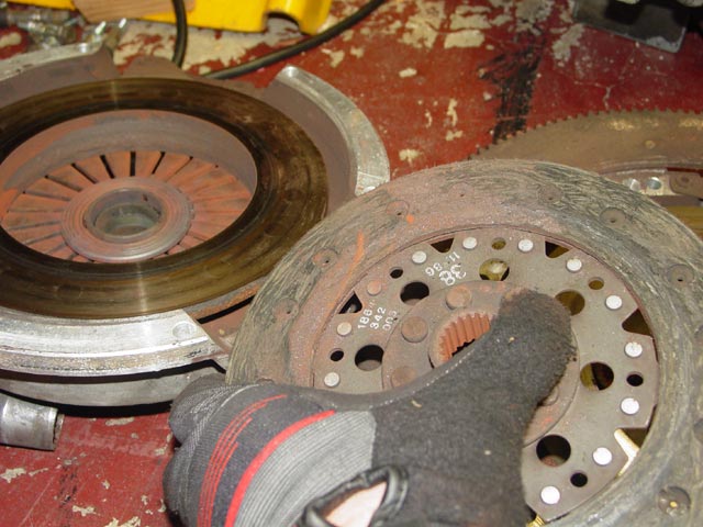
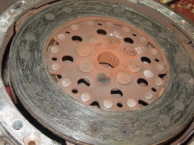
For completeness I am showing the condition of the parts within the clutch pack. Aside from the unusual amount of "rust dust" I didn't see anything particularly alarming. Below is the rear surface of the rear disc.
Front surface of rear disc, rear surface of intermediate plate.
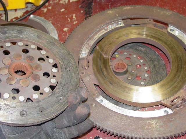
Rear surface of front disc, front surface of intermediate plate. The intermediate plate didn't look to be in bad shape; I'll hit the rusty spots with WD-40 and keep it as a spare. I'm not sure why it has the three darker spots either.
Front surface of front disc. This looked a bit glazed.
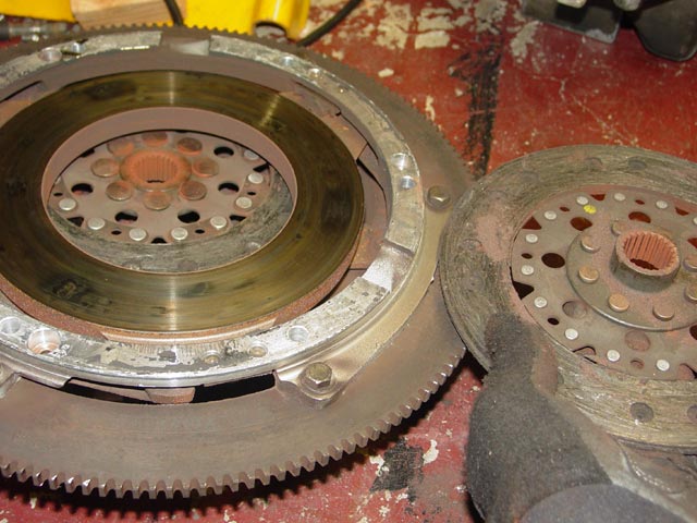
The flywheel appears to have seen a fair amount of heat. This is probably where my clutch slippage was occurring. I had planned to swap out the flywheel for convenience sake. By getting the replacement used flywheel surfaced and the clutch pack assembled & balanced without having to wait for disassembly, I hoped to save a little time, but as it turned out I had plenty of time. This flywheel would probably have needed more material removed than the one I ended up using, so it worked out OK. I cut up this flywheel to make my RMS press so it worked out in the end.
This crud between the intermediate plate and flywheel appears to be the result of sloppy work, some mechanic assembled the clutch without bothering to clean the parts. I don't think it would have affected operation, it's just... sloppy.
The transaxle lube looked pretty good for having 33K miles on it. Interestingly, the rear drain plug has no magnet on it.
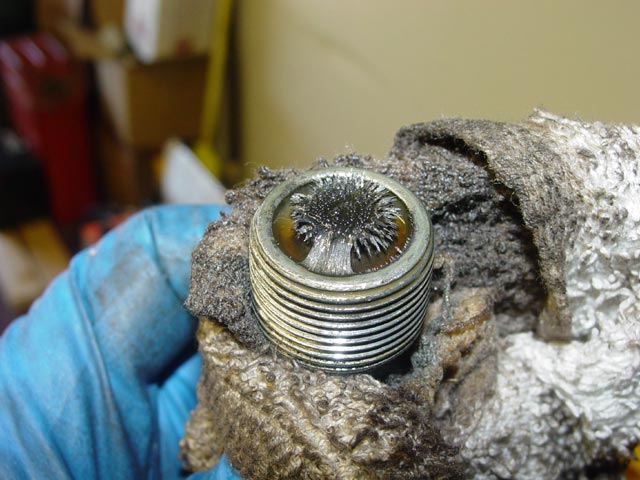
The front drain plug did have a magnet, and on casual inspection it looked pretty hairy and scary.
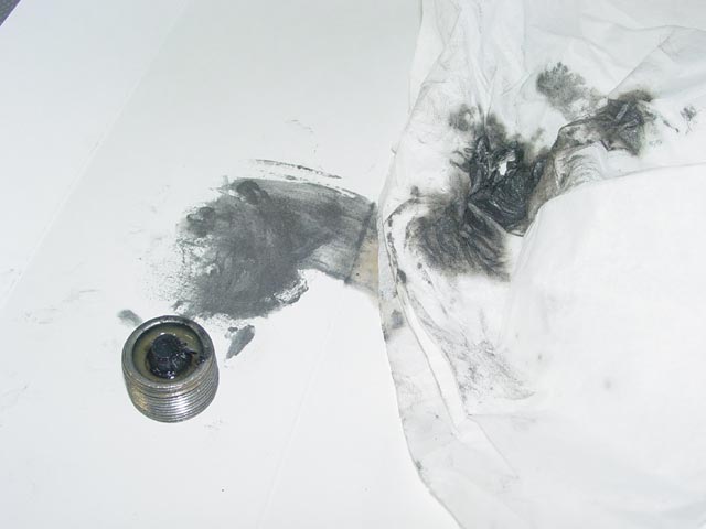
When I cleaned off the magnet and smeared the result on a piece of paper and a paper towel the metal that came off turned out to be a very fine powder. Not bad -- I was expecting chunks.
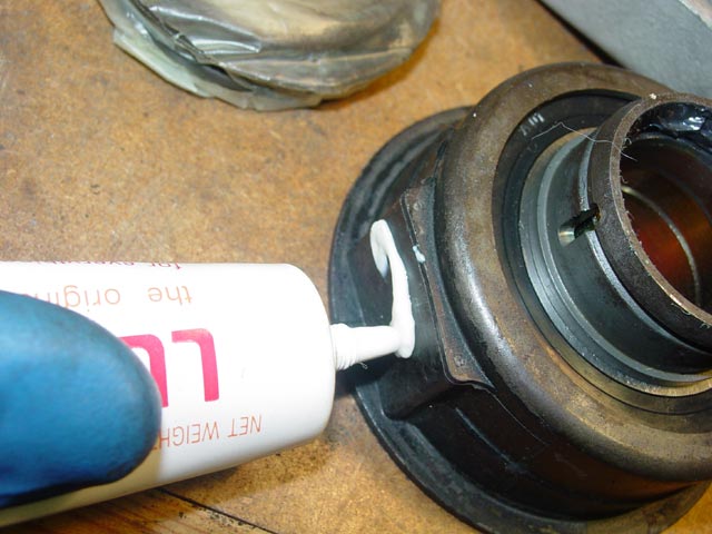
Both mounts were beginning to show cracks in the rubber. You can see a crack on the top of the rear block of rubber in this pic. It looks superficial but later I probed it with a feeler gauge -- the crack was about 5mm deep.
This turns out to be the only pic of the rear shift boot -- it had mostly disintegrated. The only issue with the old coupler seems to be age and wear. Despite the lack of a boot it did not appear to be especially dirty.
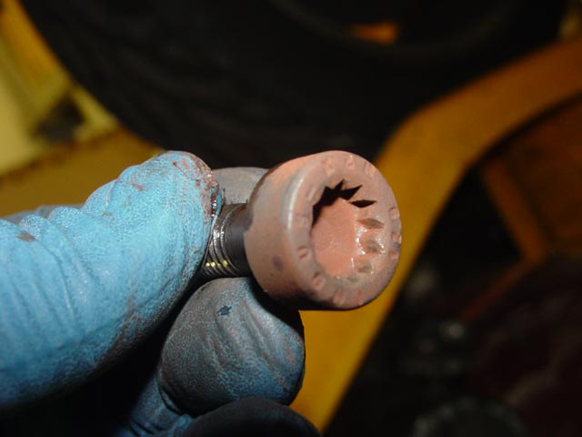
I have heard that these screw heads strip easily because of the shallow tool engagement, but I had no problems at all using an impact gun.
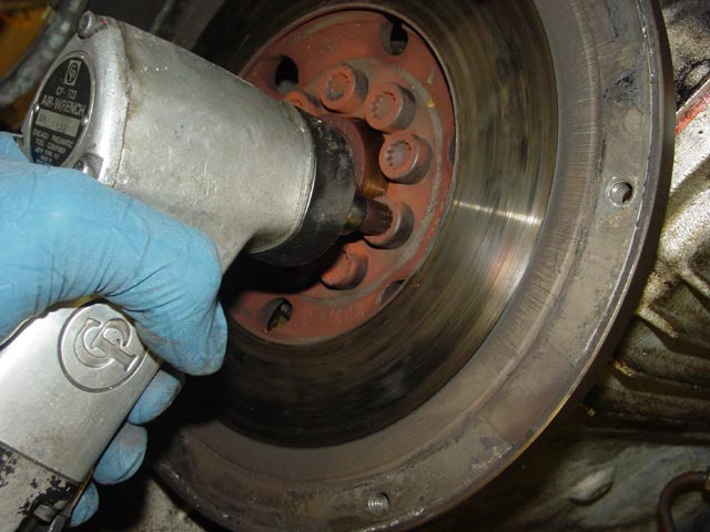
I barely even left tool marks on the bolts, though I replaced them just the same -- cheap insurance. I think the problems arise from the tight working space and the high breakaway torque. It takes a bit of extra care to remove them under those circumstances IMHO.
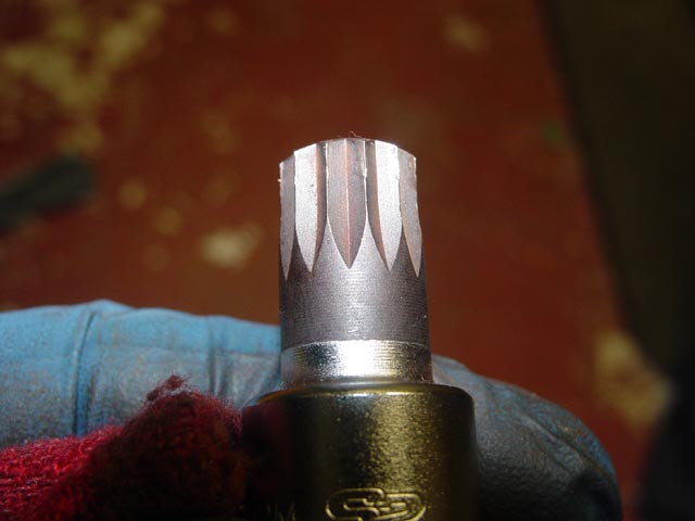
This VIM impact socket (from the VIMXZN100 set) appears to be very high quality. It was none the worse for wear after removing the flywheel.
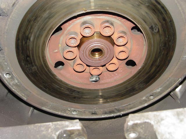
The pilot bearing felt smooth as silk with no detectable play. I had put ~35K miles on it, and the PO had the car for at least 5K miles and made no mention of clutch work, so I didn't know how old the bearing was. It was replaced on general principle. The RMS definitely needed replacement. I had planned to do it as a WYAIT whether it needed it or not.
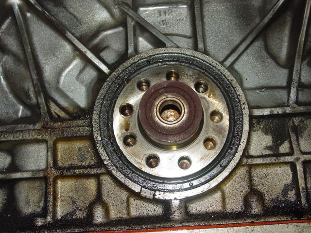
The RMS sealing surface on the crank did not appear to have any groove on it that I could detect with a hard plastic probe. There was a ring where the metal was polished but no groove.
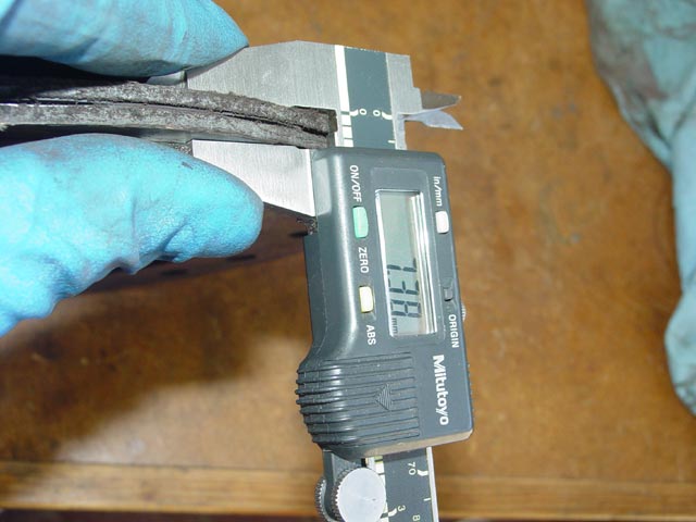
For reference, thickness of old front clutch disc.
For reference, thickness of new front clutch disc. It seeems the front disk has hardly any wear at all, though from looking at the stub shaft I know the splines must be worn.
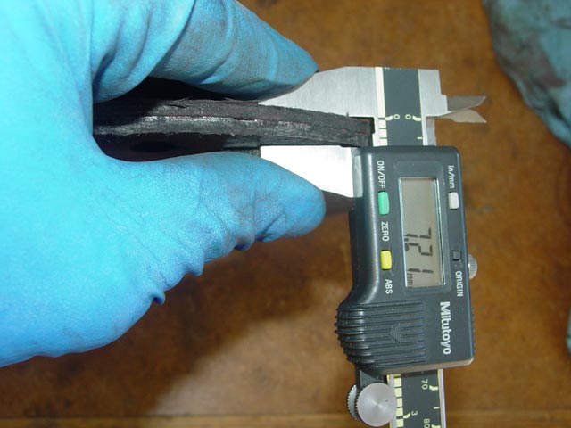
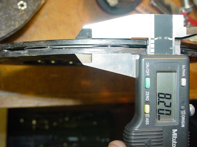
For reference, thickness of old rear clutch disc.
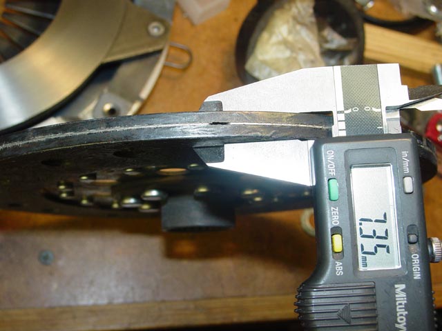
For reference, thickness of new rear clutch disc. The old disk seems to have lost almost a millimeter of material, based on the measurement of a new rear disc.
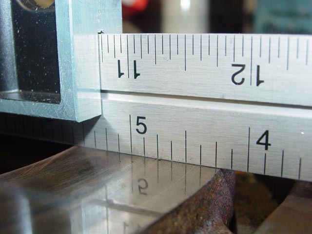
The pressure plate was pretty flat, too bad the fingers were unusable.
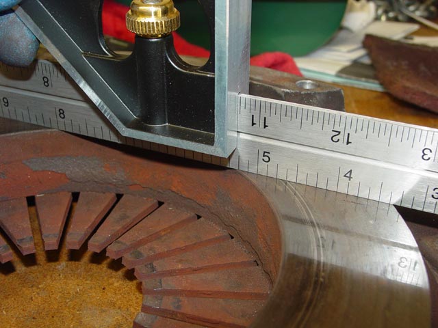
The intermediate plate is very flat, I think I'll keep it for a spare.
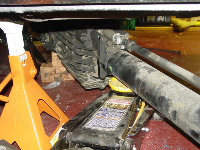
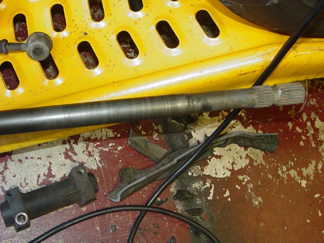
The front of the torque tube had quite a bit of rust in it, no doubt due to the fact that the inspection plug was missing. Also, the front bearing carrier had walked forward quite a bit. It had walked almost an inch forward of where I found it, then moved backward -- apparently on its own, but there is no way to be sure. I saw no tool marks or other evidence that it had been pushed backward manually. It's a bit hard to see in this pic, but the bearing was right at he edge of the large diameter, apparently it had walked forward to the point that it was no longer supporting the shaft at some point in the past.
Looking at the driveshaft you can see that the carrier was originally about a foot from the end of the tube, then it walked forward in stages over time. The bright ring near the end of the large diameter is where the carrier was when I took it apart. I find it interesting that some have said that the carrier should be 6" from the end of the tube. This would place it about where I found mine. I would think that this is too far forward, since it would be too easy for the carrier to slip forward to the necked-down portion of the shaft.
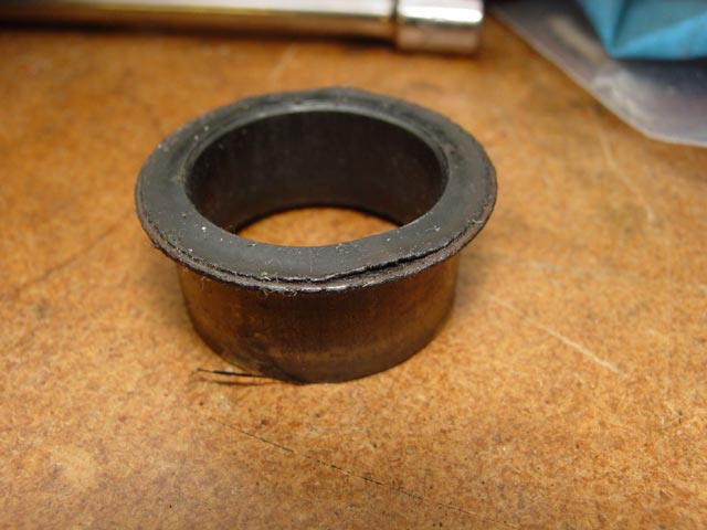
This is one of the inner bushings from the torque tube bearing carrier. It is a metal piece with a plastic lining bonded to it.
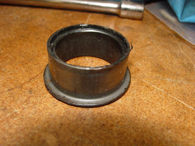
The plastic was coming loose from the steel. I can see now why this part is not always reusable.
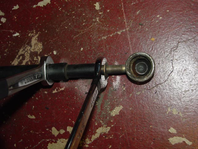
The ball cup on the shift linkage was destroyed. I count myself lucky that it never popped off. I'm sure that it eventually would have done so, given time.
Out of curiosity, I pulled the top cover off of the old transaxle. I was curious to see if, using my untrained eye, there were any visible points of wear that would account for the issues that I had with shifting.
...
...
...
...
...
...