It started with a brake warning light at SATL '07. This was on the Sunday drive to Tim's house for lunch. The brakes had been performing flawlessly up to this point, but I thought it best to play it safe and take the car home before traffic became too thick and check it over. The trip home was uneventful, and once we unpacked I took the car out to my little "test track" in a local industrial area that is deserted on weekends. Threshold braking in a straight line, it felt like all 4 tires had the same amount of bite. An inspection of all lines, calipers, and switches on the master cylinder indicated no problems. I pulled the vac line off the brake booster and swabbed around the rear seal of the MC with a pipe cleaner -- nothing.

I figured it must be an electrical glitch. I had one remaining gremlin where maybe once a week, upon starting the car all of the warning lights on the pod would stay on. I figured this had to be related, so I decided to apply the same fix to my central warning computer that had worked for my cruise control -- re-solder all of the internal connections.
Getting at the CW brain is relatively easy -- just a matter of removing the dead pedal. The CW brain is mounted to the underside. The dead pedal is the same AFAIK up to '89, and is adjustable both fore/aft at the base and for angle. The plate with three holes above my thumb engages with a pin welded to a bracket on the floor -- that's fore/aft position. The holes and slot in the tab at the other end, and the slot in the side of the unit(near top of pic) all allow you to adjust the angle. If you're happy with the initial position of your dead pedal, carefully note which mounting holes are used top & bottom before taking it all the way out.
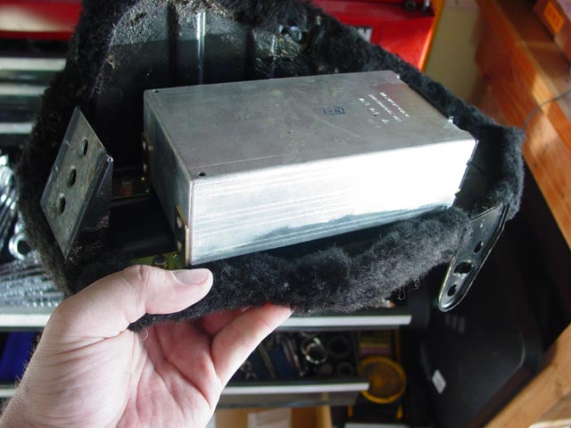
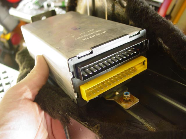
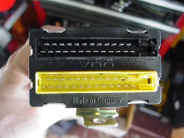
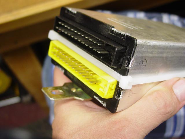
The CW brain is held to the underside of the dead pedal with three locknuts: Two above my thumb in the pic above, and one visible in the pic below. The connectors are color-coded for easy reassembly.
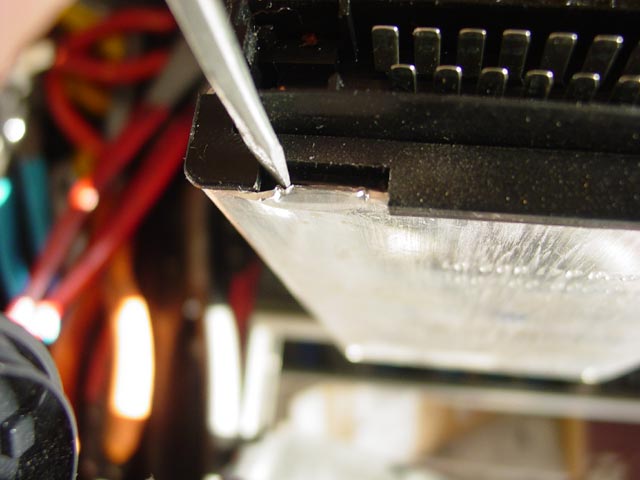
There are a total of eight places where the aluminum casing is bent into recesses in the plastic faceplate to keep it all together.
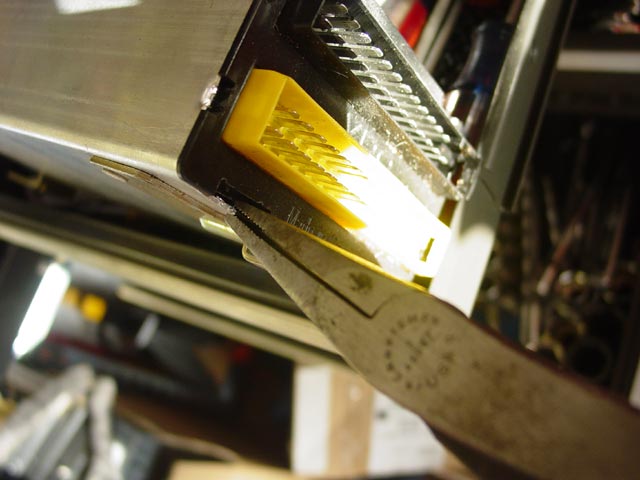
Disassembly is accomplished by first using a screwdriver to gently move the aluminum away from the plastic just enough...
...then straightening out the aluminum with some duckbill pliers.
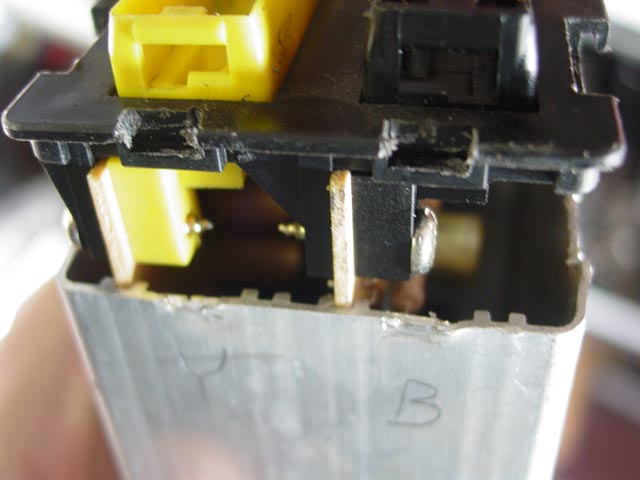
After that, the guts slide right out. I marked the casing with a pencil to help me remember how it was oriented so the harness would route properly on reassembly.
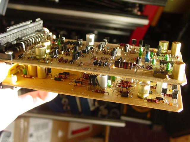
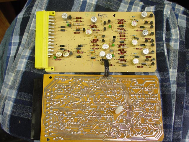
So here are the innards in all their glory. I didn't see any burnt components at this point. Also there was no anti-corrosion coating on the PCB as there had been with the cruise control. This was looking like an easy fix.
The next step is to remove the 4 screws -- 2 per side -- attaching the connectors to the end plate.
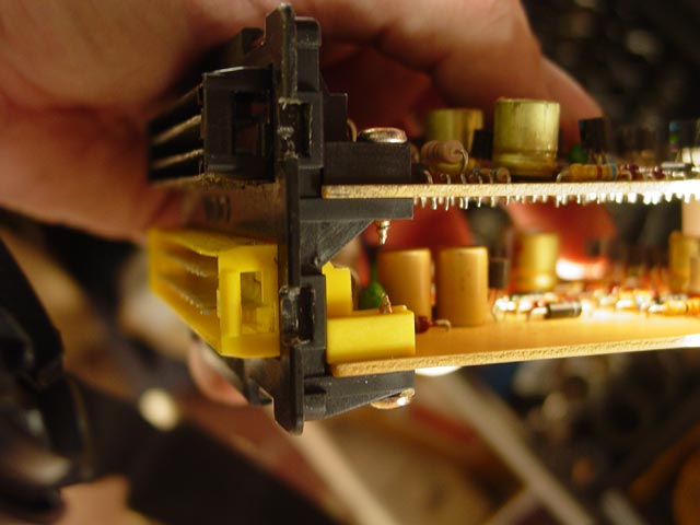
With the screws out the end plate slides right off.
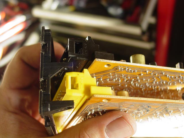
There is a plastic standoff near the middle of the PCBs that needs to be unsnapped to separate the two PCBs.
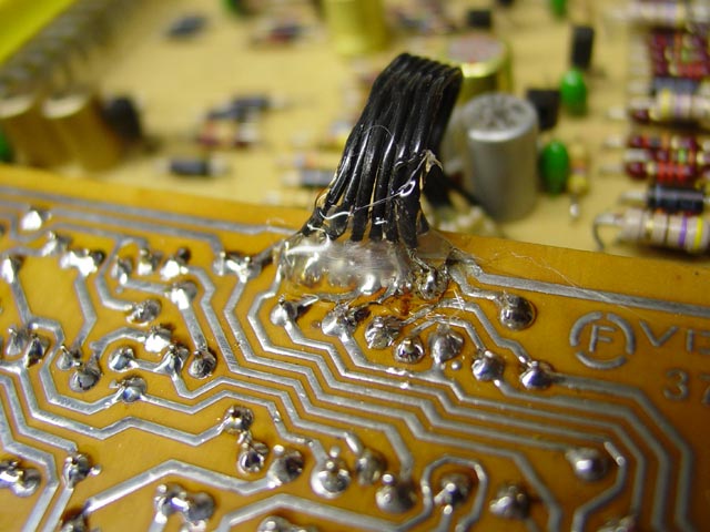
There is a small harness connecting the two PCBs. There is glue over the solder joints on one side, easily removed with a combination of carb cleaner, a toothbrush, a toothpick, and some patience. There is no need to clean the glue off of the other PCB, you can reflow the solder joints on that side with the glue in place.
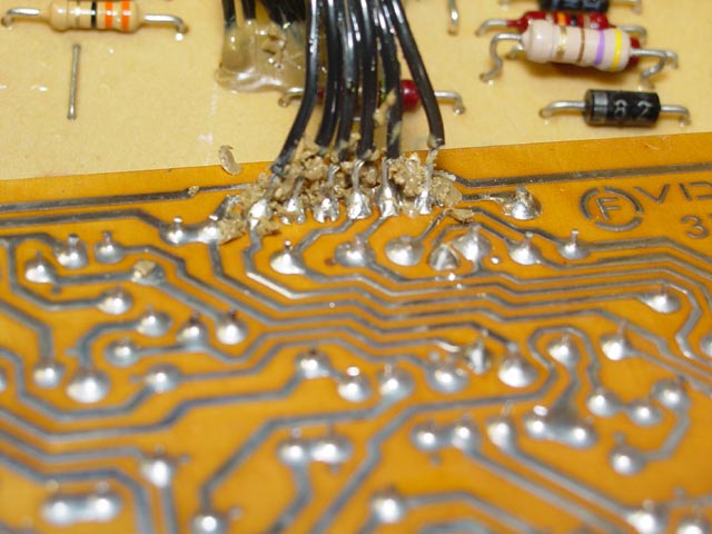
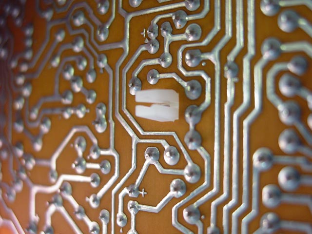
This part required an extra dose of patience... there are a LOT of solder connections in there! I carefully soldered each joint, taking care to not keep the heat in one place for too long for fear of heat-damaging components. You also have to be careful not to bridge connections that are close together.
When I had finished the soldering step I potted the wires in hot glue to act as a strain relief, just as the original glue was intended to do.
With that I reassembled the unit back in its casing, securing it with zip ties until such time as I'm convinced I won't need to fool with it again. At some point in the future, when I feel confident I won't need to open this up again, I will bend the aluminum tabs back.
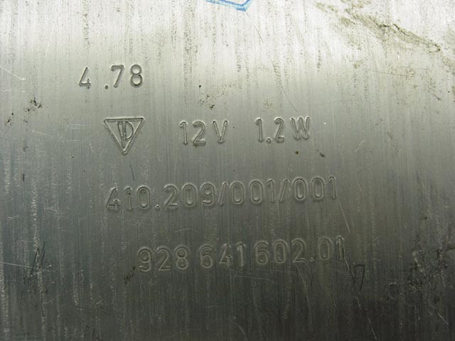
I recorded the markings on the case of the CW brain for posterity. FWIW it seems to be original, based on what I take to be a date code of 4/78 which agrees with my car's 5/78 build date. Also the mounting hardware looked untouched.
Nearing the end of the weekend I buttoned things up and took it for a test drive. Still had a brake warning light!
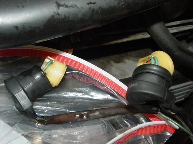
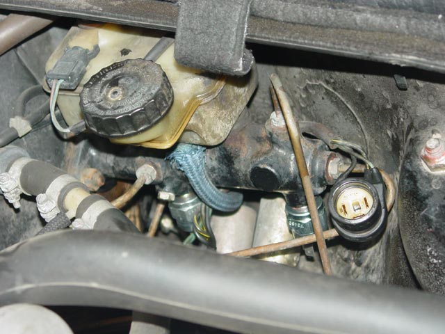
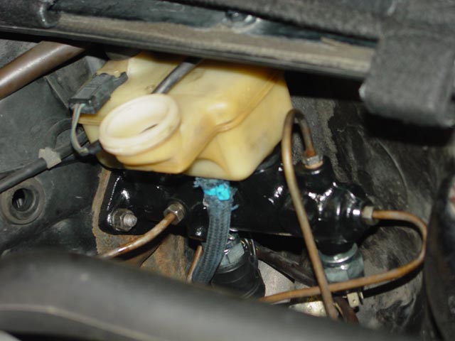
 I went back under the hood to verify the function of the switches on the master cylinder and found the rear one was now leaking. Note, the liquid on the reservoir and the hard lines is water -- I always wash at least my fenders and bumper before using my service covers to avoid scratching. The liquid on the connector boot is brake fluid though. I guess that the internal seal on the switch let go some time back and just took a while to get to the point where it was visible. In my first round of checks I had both connectors off and they were dry.
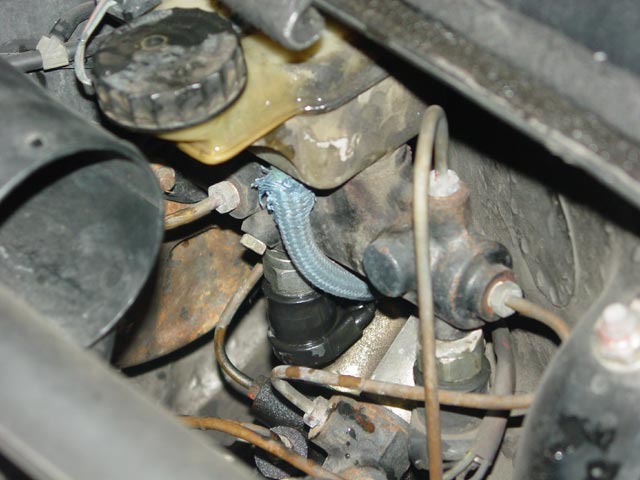
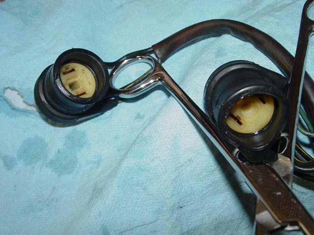
I immediately set about cleaning the brake fluid out of the connectors. The front had just started dripping -- nowhere near as bad as the rear, but I wanted to clean them up ASAP before the brake fluid could do much damage to the rubber. I pulled the connector pieces out of the boots and, dangling them down inside a plastic bag, hosed them out thoroughly with brake cleaner.
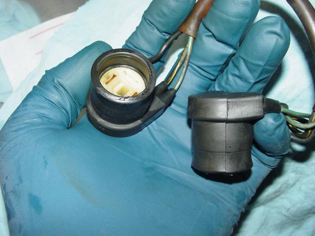
I hooked them on this set of forceps to dry after reassembling them. They were pretty dry inside when I started the reassembly but I sprayed them with a bit of LPS-1 silicone to make them easier to assemble and to condition the rubber a bit.
Here they are after having dried for a while.
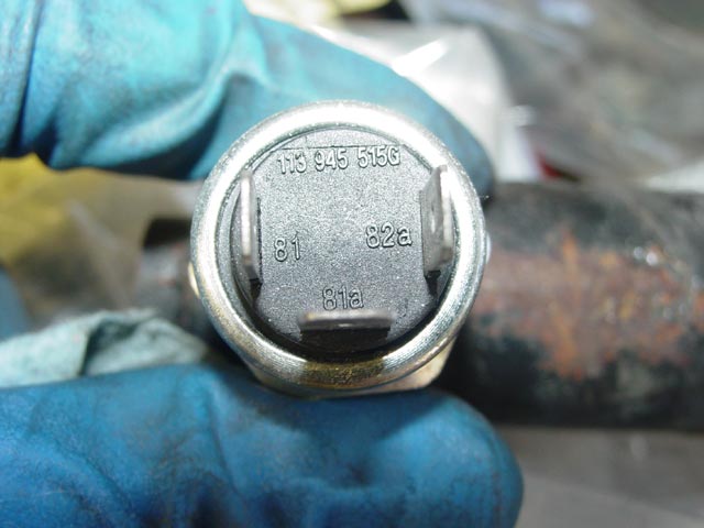
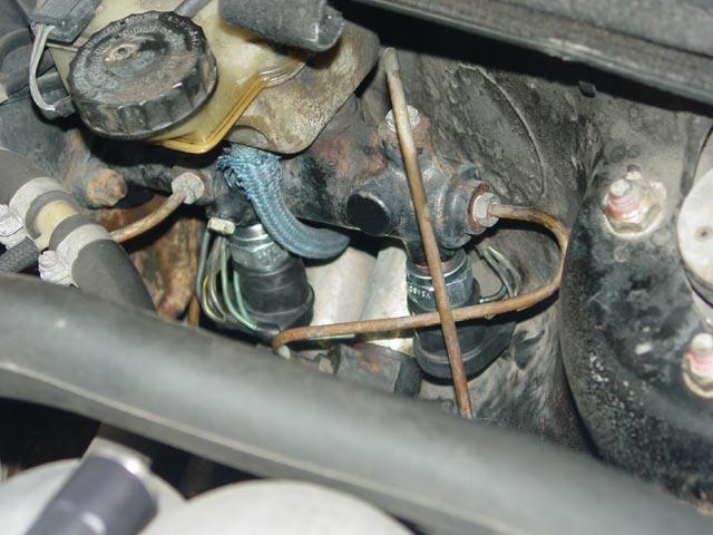
Just for reference, below is a picture of one of the pressure switches showing the terminal labels.
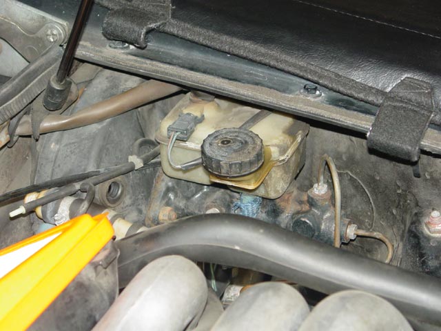
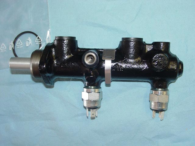
So, here is the master cylinder with new switches installed. Very little brake fluid leaked out.
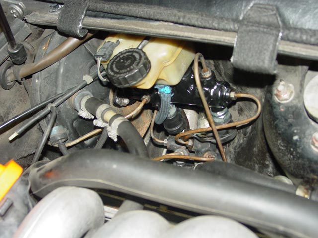
Connectors in place...
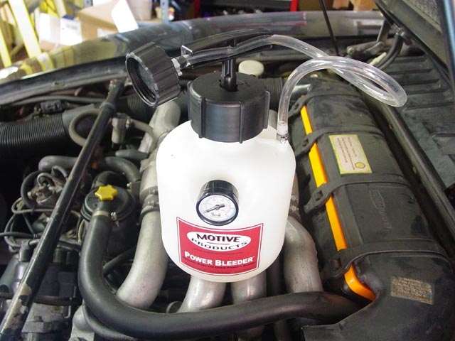
I used my trusty Motive bleeder to bleed the brakes. It seemed unnecessary, since I didn't get any bubbles out of the system. I think the small amount of air that was introduced by changing the switches simply bubbled straight up to the reservoir. It was about time to refresh the fluid in the system anyway, so it wasn't a complete waste.

OK, happy ending, right? Noooo...
 I took it out for a test drive and immediately saw the brake warning. Believe me, I fiddled and fussed, ran through lots more brake fluid verifying there were no bubbles in the system. At this point, I could only conclude that the master cylinder was faulty. Now, it seems pretty strange that the switches would begin to leak and the master cylinder would go bad all within a week. Maybe it makes more sense than it would seem at first glance though.
 Here is the theory that I came up with. While on the fun run, either or both of the switches started to flake out, OR the master cylinder started to flake out. Once I got it home and started experimenting, I was standing on the brakes HARD looking for signs of uneven braking. I couldn't detect any and finally had to resort to checking to see if the wheels locked up at the same time. The brakes are arranged in two diagonal circuits, which ought to keep the car braking straight if one circuit has failed so I was looking to see if one side locked up before the other. Both fronts tended to lock up at the same time so it seemed the MC was OK. It must have been during this testing that whichever part decided to fail second -- whether the switches or the MC -- finally let go.
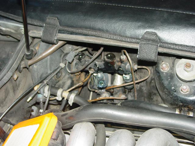
So, the next step was to order a new master cylinder. Note that the rubber grommets for mounting the reservoir are not included -- you have to ask for those too. Once it arrived, I set to work. First I removed the air intake tube, the top of the airbox, and the vac hose to the booster to give me room to work.
Next, I emptied the reservoir and the MC as much as possible by propping up the Motive bleeder so the pickup tube would suck air, and opening up a bleed screw at each front caliper until I started to see air bubbles.
I removed the blue hose, then pulled upward on the reservoir, wiggling it back and forth to free it from the old grommets.
By taking the approach of forcing air into the system, I kept the spillage of brake fluid to a minimum. This is probably not the best approach if you don't have a power bleeder(or if you have ABS), but it worked for me.
Next, I pulled the connectors off of the switches. Side note -- pull the connectors off and move them as far away from the master cylinder as you can BEFORE you start making a mess with the brake fluid. You'll see why in a minute.
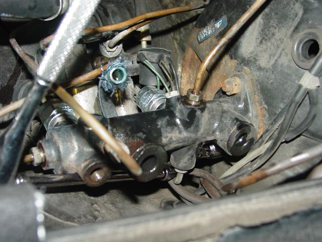
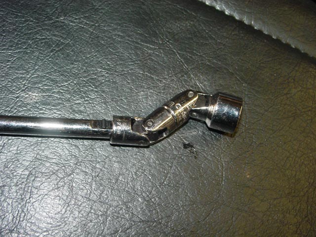
The outboard nut on the master cylinder is a huge pain in the ass to get to. Because of the line that comes off the same side of the master cylinder and because of other instructions it seems there is no way to get an ordinary wrench in there. Here you can see my solution in action... The brake line that wraps around the tool cannot be reached with a flare nut wrench. You have to disconnect the other end of this line from the proportioning valve.
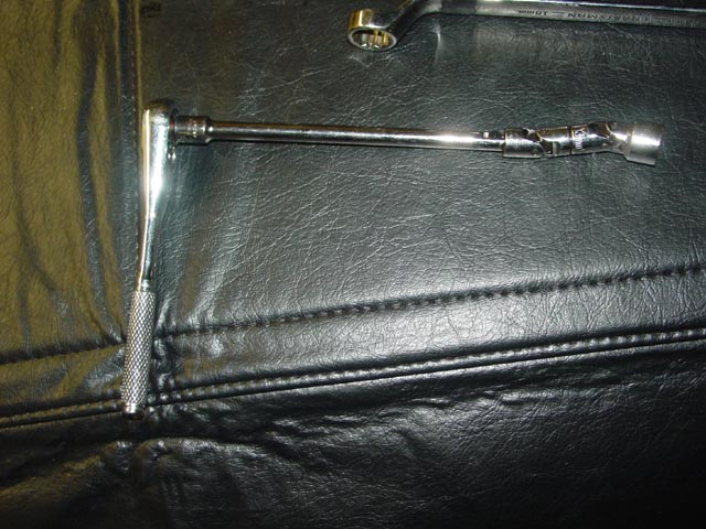
I used a 1/4" extension, a universal adapter, and a 13mm universal socket.
The pic above was taken before I managed to get the nut out, I had only managed to reach it. It turns out(heh) that the universal joints have to be lined up like on an automotive drive shaft or it won't work. What happens is the universal joint moves in and out as it turns unless the pivots are lined up as shown below. You'll need to set it up as in the picture below to do the job. Note, there was a change with the 1986.5 cars that eliminated half the hard lines at the master cylinder -- the later versions are much easier to get to and don't require this tool.
OK, now this was pretty farkin' annoying.
 Remember my advice about moving the connectors out of the way... and remember how I had to pull them apart to clean them? Well, I had to pull them apart and clean them again, because I spilled brake fluid inside of them. One only got a few drops in it, but brake fluid is murder on rubber, and I didn't know if these boots could handle it. I played it safe and cleaned them both up again.
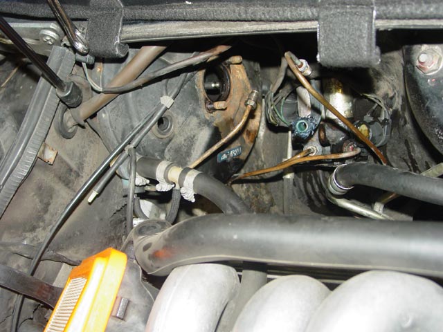
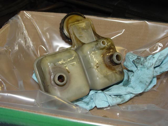
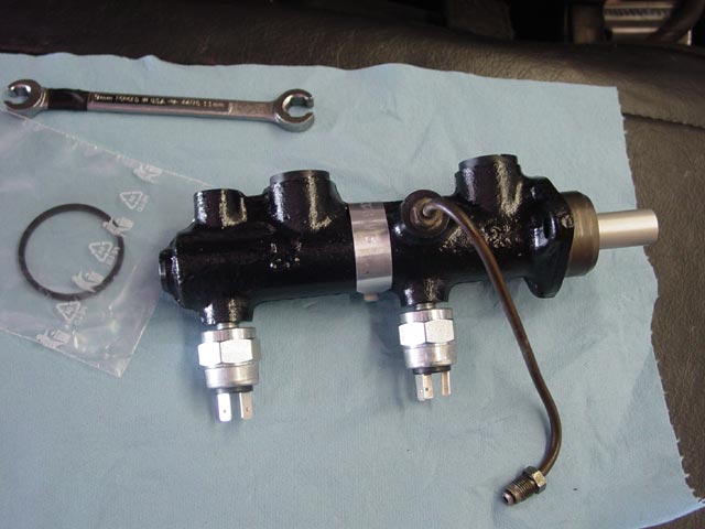
The new master cylinder came with switches already installed, and it came with a new seal for where the master cylinder meets the brake booster. Picture was taken after I installed the new reservoir mounting grommets.
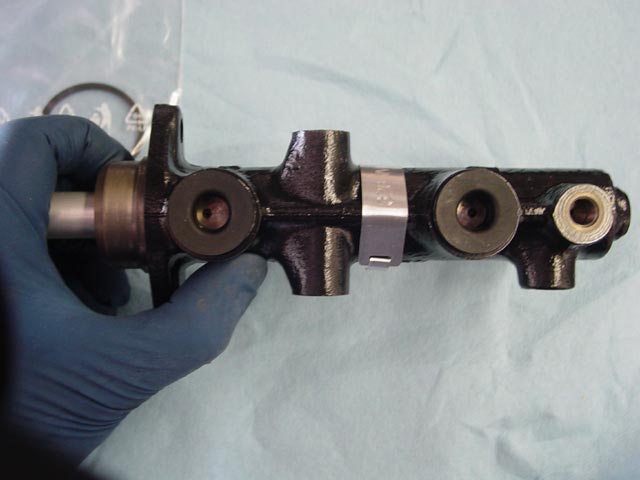
Here is a top view, showing the relatively small ports that allow fluid to enter the master cylinder, provided that the brake pushrod is not adjusted too far forward. I used a depth gauge to confirm that the detent in the MC that the pushrod engages in was at the same depth on both the old and new units. Any difference here(more likely in a rebuild IMHO) would require adjustment of the pushrod.
I transferred the hard line that can't be reached with the MC in place to the new unit, carefully noting the angle at which it was mounted on the old MC and duplicating that angle as closely as possible.
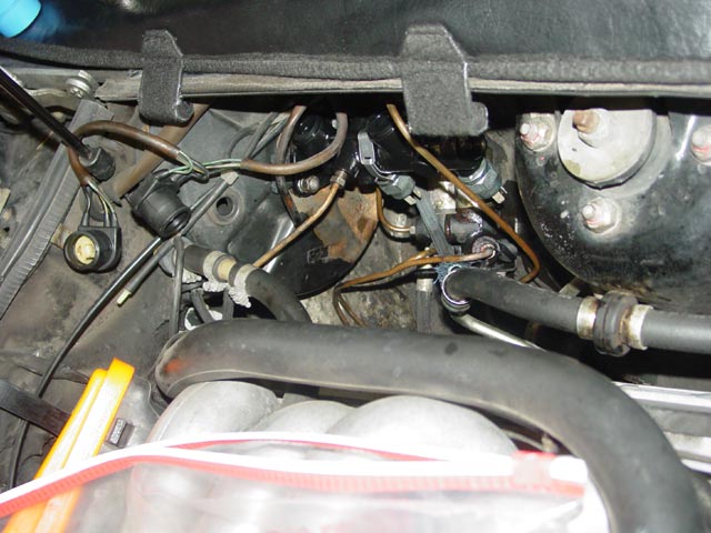
I cleaned up the sealing surface on the brake booster, installed the seal on the rear of the master cylinder, and mounted it up -- "reverse of disassembly". Note the switch connectors well out of the way.

That outboard nut was even tougher to get back on than it was to take back off. I used the same tool with the addition of some electrical tape. Some tape went inside the socket, and the nut pressed into the tape to hold it in place. I also put a wrap of tape around the universal joints to keep them from flopping around. With the tape in place it would hold its shape; this allowed me to get the nut started, and later allowed me to pull the nut free from the tape by simply pulling forward. Here is what it looked like when I was done.

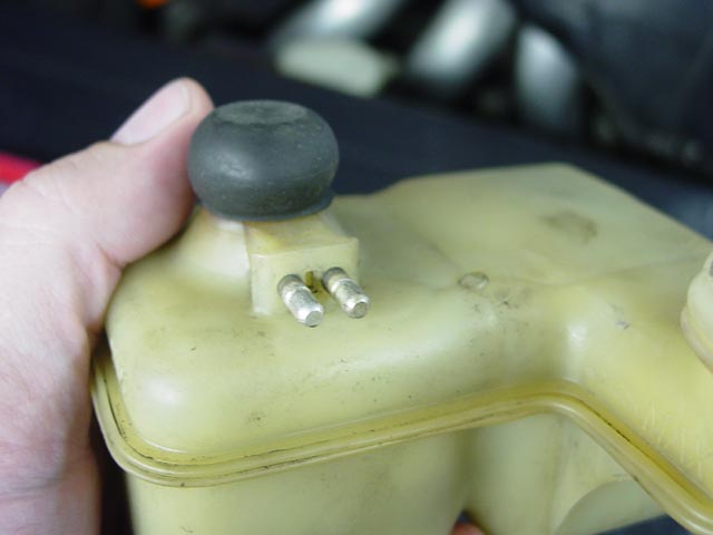
This is an interesting feature on my reservoir. It's a spring loaded button, its only purpose seems to be for testing the brake fluid low level warning. Pressing it downward activates the warning.
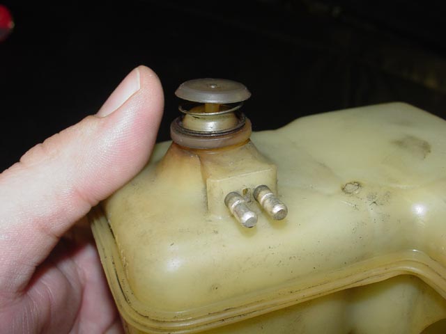
This rubber cap that goes over the test button was a bit hardened up and seems to be NLA except as part of the whole reservoir assembly. I noticed its condition when I pulled the reservoir off and I soaked it in LPS-1 silicone while I worked on the rest of the job. It softened up nicely and ought to be good for a few more miles.
After cleaning up the brake fluid in the area with brake cleaner, I reattached the switch connectors. It was a bit of a pain to get them back to where they belong, and it would have been much more difficult with the reservoir in place.

I cleaned the reservoir thoroughly with brake cleaner and compressed air. Next, after swabbing a little brake fluid on the nipples at the bottom of the reservoir to lubricate them, the reservoir just presses down into place. The blue hose looked fine, the braided jacket was just a bit frayed. I tie-wrapped it in place so it would not come loose during bleeding. I'll replace it when the day comes that I have to replace the clutch master.
Last thing before bleeding was to add the strainer that goes under the MC fill cap. This too was cleaned with brake cleaner and compressed air. From this point on it was all gravy. I pulled the rear wheels off(fronts were already off), filled the reservoir about half full, and hooked up the bleeder with a couple quarts of DOT3 fluid. I bled in the following order: RR, LR, RF, LF, clutch slave. I went through most of the 2 quarts of fluid since I had introduced so much air into the system by purging the reservoir and master cylinder, but with the Motive power bleeder it was very easy. I just had to keep coming back and pumping it up to maintain 10PSI.
Bleeding the clutch was no big deal -- it didn't have any air in the system, I just bled it to make sure the fluid was clean. One of the reasons I only filled the reservoir about half full initially is because when finished bleeding, you tilt the bleeder up so the pickup tube sucks air as in the pic above(2nd pic on this page that shows the bleeder) to clear out the line on the bleeder for storage. At that point I just topped up the reservoir, a couple more ounces. When I was finished, I installed the nice new set of rubber bleed screw caps on all 5 nipples.

After putting the wheels back on the car, putting the cap back on the reservoir, reconnecting the vac line to the booster, and reinstalling the airbox and air intake tube it was time for a test drive.
After all this, the brakes worked perfect -- maybe a tiny bit firmer than before replacing the MC, it was hard to tell for certain. It might have been my imagination wanting to notice a difference after all that work. Most importantly -- no more brake warning light! As a side bonus, the occasional glitch with all warning lights coming on after startup is gone as well.
