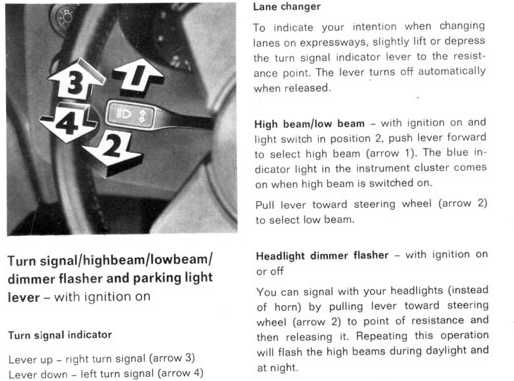
I had noticed a long time ago that the "Headlight Dimmer Flasher" mentioned in the owner's manual(pic below) didn't actually do anything.
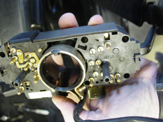
During my "Poddysey" I noticed that there is an unused pin on the combo switch(top right of pic below, pin 56a), and I could see by looking at the switch that there is a contact that connects to this pin when the lever is pulled back. You can see part of the spring for that contact through the rectangular hole in the plastic just above that pin.
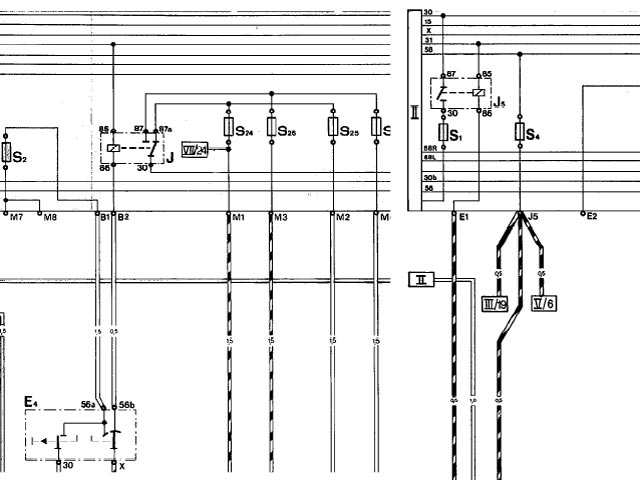
That started me looking at the wiring diagram, and on the US diagram that pin activates driving lights, the circuit for which is only present on Euro cars. The circuit is on P. II of the wiring diagram, current track 15. You can see it on my first diagram below, where it goes through fuse S2 and out terminals M7 and M8.
So, I posted a thread on Rennlist to find out how other owners' cars behaved when this switch is pulled. Matt(FlyingDog) pointed me to some helpful info on the 84 Euro wiring diagram, but when Chuck Schreiber quoted an article from the 7/78 issue of "Upfixen Der Porsche" I really knew I was on the right track.
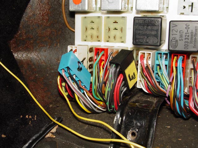
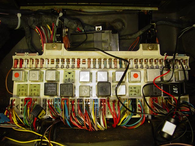
From Chuck's reference I knew I was interested in terminal E1 on the central electric panel. That's the pin that energizes the coil on relay J5, turning on the fog lights. It's on the right side of the pic below. The diode mentioned in the "Upfixin" article would not be necessary if I only wanted the foglights to flash. However, I also wanted the high beams to flash when pulling the lever if the headlights happened to be on at the time.
Getting the high beams to activate is a bit more involved. The relay "J" on the left side of the diagram below switches between high and low beams. Note that the diagram is pieces from two pages of the original diagrams pasted into the same image. In the center of the diagram you can see all of the high/low beam fuses. The way this is wired, power to the coil of the relay, applied at terminal B2, causes the low beams to be illuminated. When the power to B2 is interrupted, the relay switches over to the high beams. The portion of the cicuit that controls whether the headlights are on in the first place is not shown, because it's not relevant. If the headlights are not on, the state of connection B2 is ignored.
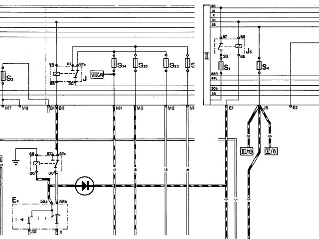
Since the wire I would be adding would provide +12V when the lever is pulled, I needed to add a relay that would normally do nothing, but would interrupt the B2 connection when the lever is pulled in order to control the high beams. I needed a diode where this power connected between the fog light circuit and the high beam circuit to prevent normal operation of the foglights from activating the high beams.
So, this is the circuit diagram that I ended up with. Remember, the connection to B1 doesn't really exist. I have removed it from the diagram, but that didn't require any change to the car. Note that I am using the NC contact on the relay to leave the circuit path to B2 intact under normal conditions.
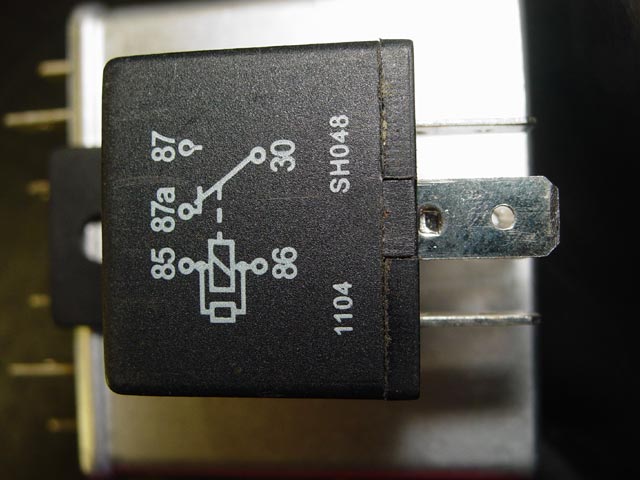
I ordered up the wire and connectors that I thought I would need(list at bottom) and found a relay locally that had NC contacts. As you can see from the pic below it's a very common type but when I went to the local VW gearhead shop, Bugformance, they did their usual "I don't know nothin' without a VW part number" routine. Even the independent parts guys down the street didn't know what I was talking about. They tossed a catalog on the counter and I had to find likely relays and ask if they had the number in stock. What a pain. Used to be you could just walk in some random parts shop and say, give me a DPDT 12V relay and they would toss it on the counter and say, "Anything else?"

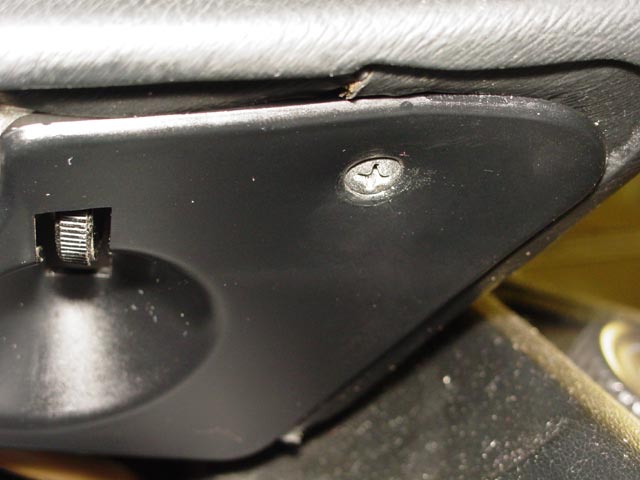
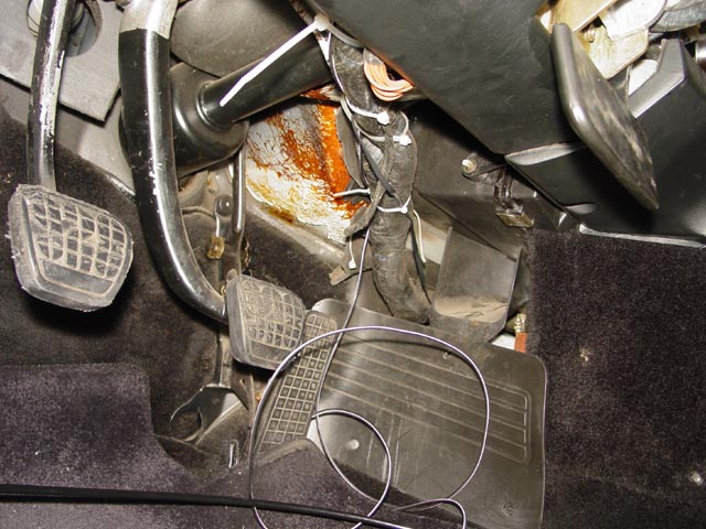
So, this is a partial repeat of the Pod project(Podject?)... the lower trim piece comes off the pod, one screw on the right:
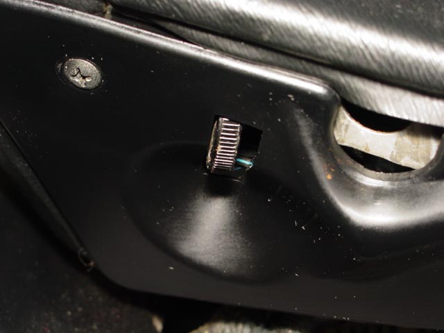
And one screw on the left. Be very careful as you work the trim piece down and forward, disengaging it from the center plastic piece takes a little patience if you want to do it without breaking anything.
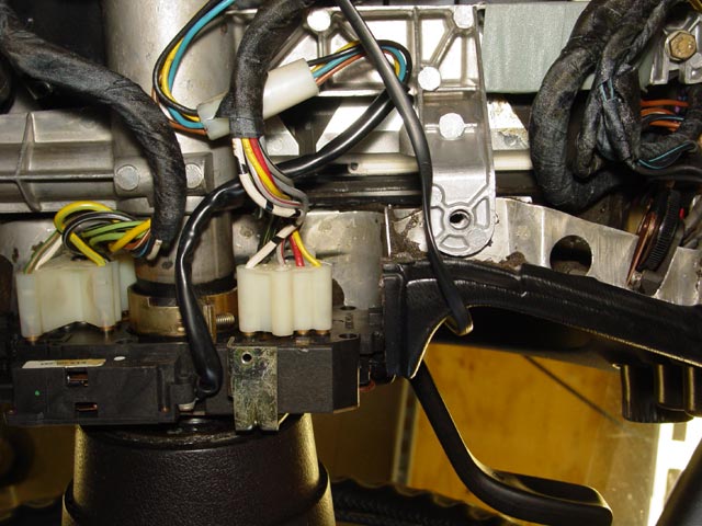
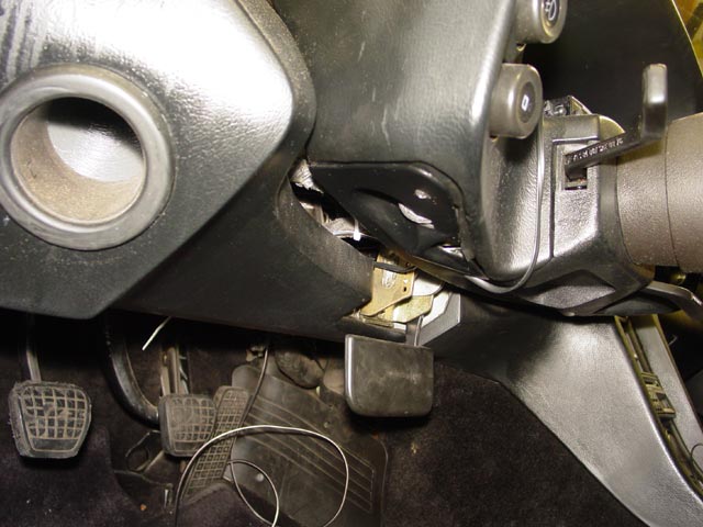
Next, the phillips screw and two M6 hex head screws come out. The plastic piece that covers the lower half of the combo switch can be removed without removing the wheel, you just have to take a little care jockeying it past the various switch stalks. This step may not be absolutely necessary, but I wanted to be able to take clear pics of the process so I pulled it out.
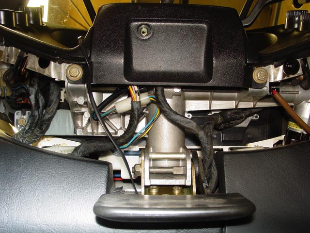
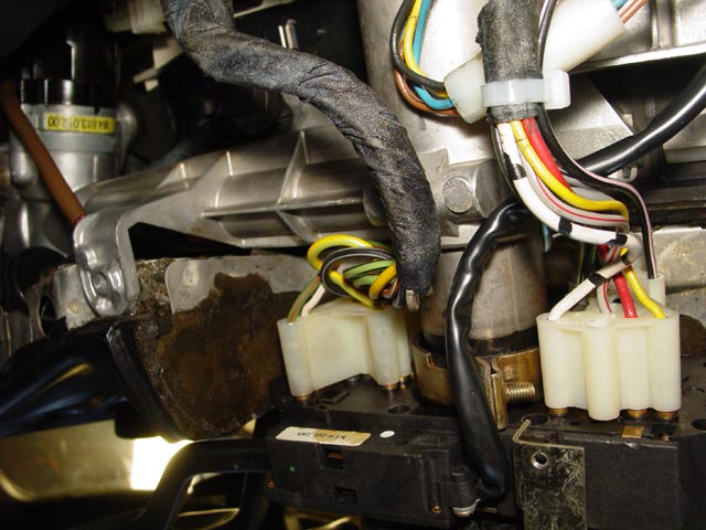
So here it is, exposed. The connector that needs to come off is the one nearest the center of the pic.
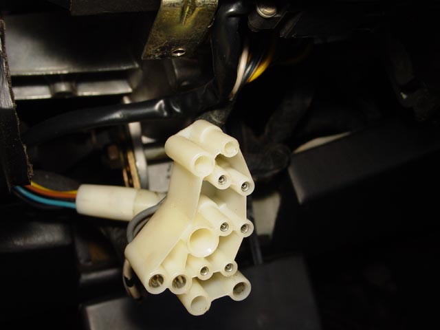
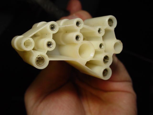
Here is the connector. The position where I need to add the terminal is the largest one on top, just left of the center of the pic.
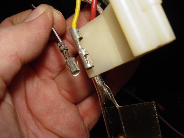
FYI, the terminal extractor tools sold by EagleDay do not work on these 3.5mm terminals. Just for grins, I tried using the tang of an X-Acto razor saw(the small 40 TPI version) and it worked perfectly. I was able to compare the new terminal(Left) with one of the original 3.5mm terminals, and found that the new one is an excellent match. Note that the original terminal does not have one set of tangs crimped over. Apparently this is to help position the terminal in the connector, and I should have looked at the original first. It worked out fine though, it seems that it's not that critical. The wire from EagleDay, black with pink trace, turned out to be a decent match for the "black with pink dots" wire that activates the foglights down at the panel.
Next, I snapped the two terminals into their respective sockets on the connector.
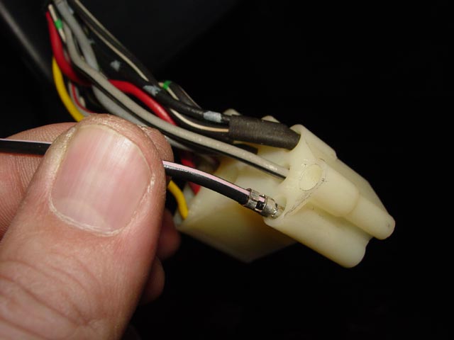
And here is the connector, ready to go back on. Almost ready, that is. I put a dab of Stabilant on the new terminal before reinstalling the connector.
With the connector in place on the combo switch, I ran the new wire alongside the existing harness.
There were already some tie wraps on the main harness from when I ran my V1 remote. I had left them slightly loose, so the new wire slipped right in. I added a couple more just to tie things up neatly.
Once I had the wire routed past the lower section of the dash, I buttoned up the pod, putting the two plastic pieces back in place. The new wire is barely visible between the pod and dash, and only if you bend way over and look at just the right angle.
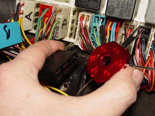
Next, I started digging into the CE panel. I had to pull connectors B and E, and I pulled the defroster relay to get a better grip on them.
Next, I extracted the B2 and E1 terminals from the connectors. Here I am using the EagleDay extractor, but a dental pick works OK as I have shown elsewhere on this site.
OK, time for a beer!

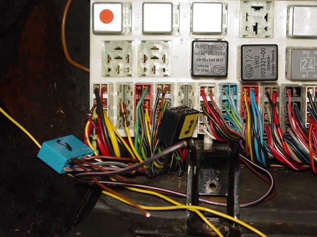
 At this point I had routed the wire all the way over to this side along the main harness. I had pulled out my so-so V1 wiring job, and started to work on the ground wire that I needed for the relay. The V1 power distribution block had been put in place somewhat hastily and I hadn't really finalized the location. I was waiting for the next time I had the CE panel out to put the finishing touches on it.
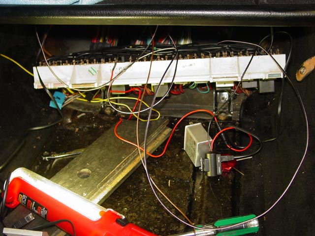
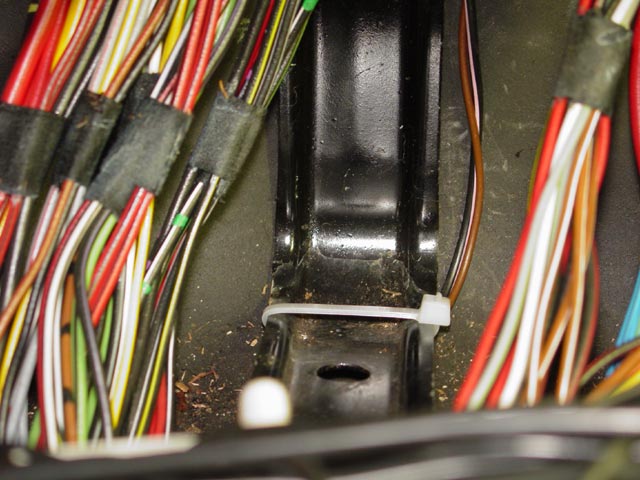
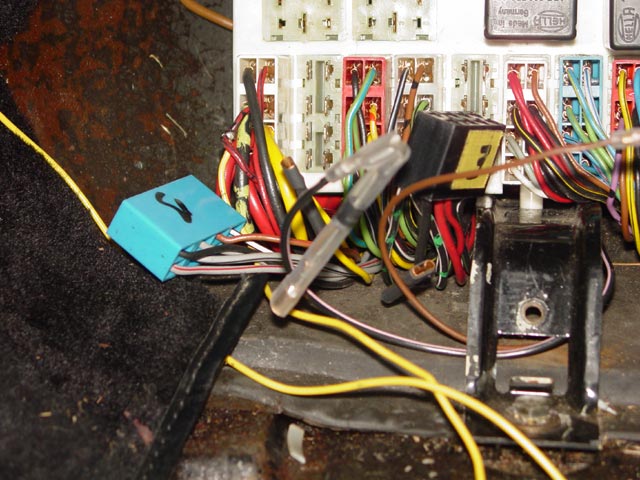
Here you can see... well, actually, you can't see the wire running above and behind the harness. The new wire and the V1 remote wire go through both tie wraps shown. The new wire then turns downward and runs along the right side of the left mounting bracket for the CE panel. It comes down behind the ground wires. I added the ground wire for my relay here, using a hardware store 1/4" ring terminal that I pulled the yellow plastic collar off of, then crimped and soldered it to the wire. I then routed the two of these wires together down the side of the bracket.
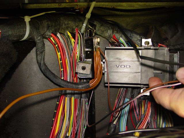
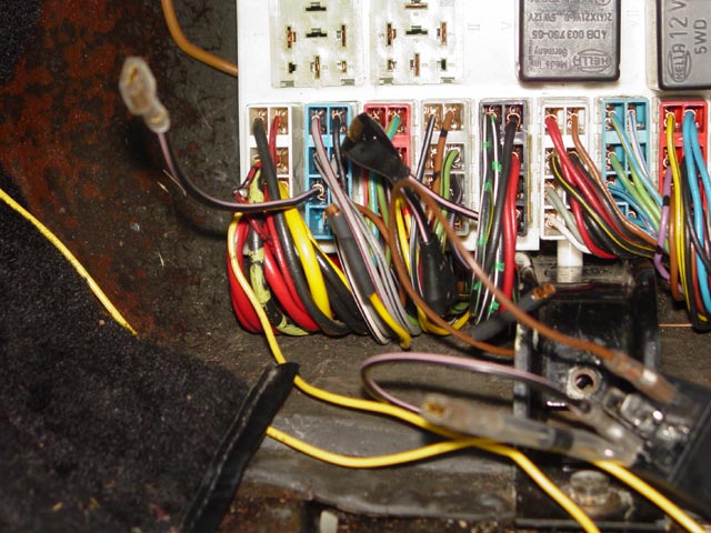
Here they are making the turn at the bottom of the CE panel bracket. It's a bit hard to tell from this angle, but the tie-wrap is tight on the bracket, and because of the cross-section of the bracket it leaves a loop on the side that the wire slips through.
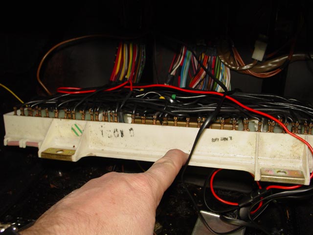
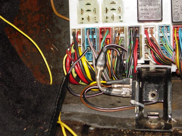
The V1 power is tapped off of a blade connector to the otherwise unused fuse 13, which gets power with the ACC circuit. Very plug-n-play. I tucked the red power wire under some of the black CE wires just so it wouldn't flop around and try to get away. I brought it up to the right of the righthand mounting bracket for reasons that should become obvious later. No, I'm not really pointing at anything, just holding the edge of the panel down so I can get a pic.

At this point I was ready to put the panel back in place. For the moment, the V1 wires are just sort of shoved out of the way, over to the right. You can see the new flasher & ground wires coming forward just to the right of the left CE panel mounting bracket.
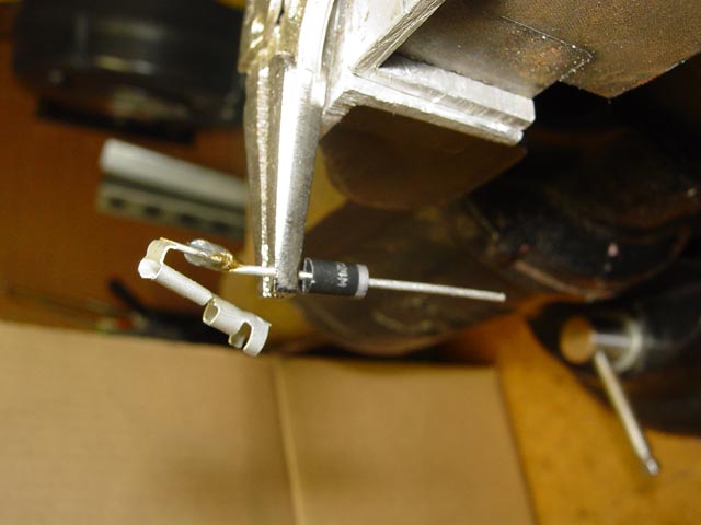
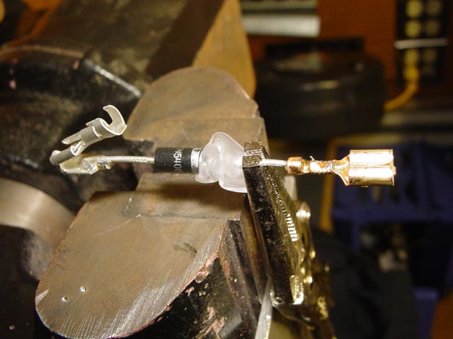
The next step was to begin fabricating up the pieces that I planned to use to get the job done without altering any part of the original harness. I decided to have my trigger wire activate the relay directly, and attach the diode directly to that terminal. I fed the diode lead through the hole in the terminal and squeezed it down into a fairly secure mechanical connection. It's usually not a good idea to rely solely on the strength of the solder joint. The needle nose vice grips were there as much to act as a heat sink to protect the diode as for holding the part for soldering. This is a very rugged diode, rated up to 200V. That's way more than I need but was the same price as a lower-rated diode, and just might last longer.
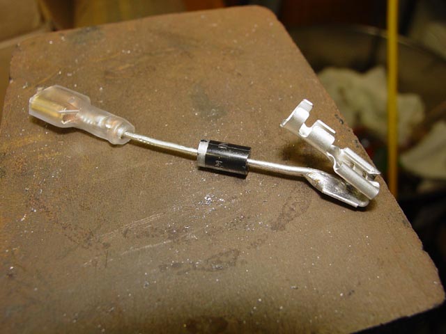
I then crimped and soldered a female blade connector to the other end of the diode. I did it this way because if the circuit is ever disconnected, I don't want a male terminal here that could short to ground. The white thing scrunched on there is the soft vinyl boot that covers the terminal. I was a little cramped for space and had to ball it up a bit to get enough room to solder.
So here it is, basically assembled.
I then covered the entire diode and female terminal with heat shrink tubing. You may be wondering at this point why I bothered with the soft vinyl boot. The main reason is because I didn't have any smaller size clear heat shrink on hand, and this size did not shrink tightly enough against the female terminal to suit me. With the extra vinyl in there it's tight and can't possibly move. Also, it will seal better with the mating terminal.
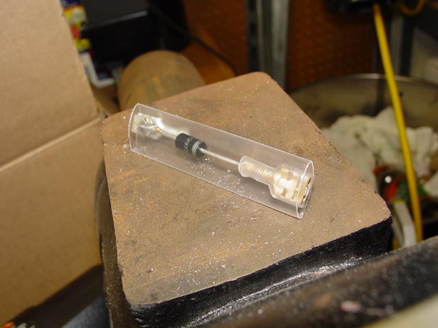
I used clear heat shrink so that if anyone else ever needs to work with this circuit they can tell there is a diode in there. Also, when diodes fail they often crack or burn the case, so this allows visual inspection.
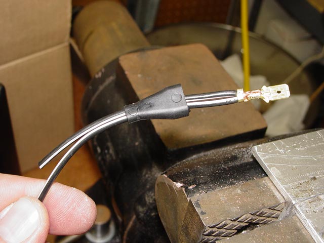
Next, I started making the mini-harness that allows me to tap into the fog light circuit. This connector is where the diode will attach. Basically I stripped an inch or so of insulation from the middle of the wire, folded it, twisted it up, and crimped it in the terminal as shown below. Next I soldered the connection, and pulled the boot up around the terminal.
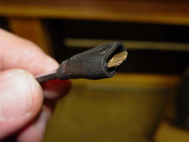
Here is the finished connector. Pretty slick setup. It looks more in keeping with the rest of the connectors on the car than those damned blue hardware-store connectors, which I'm not above using for test cables etc. but which don't belong on a shark IMHO.
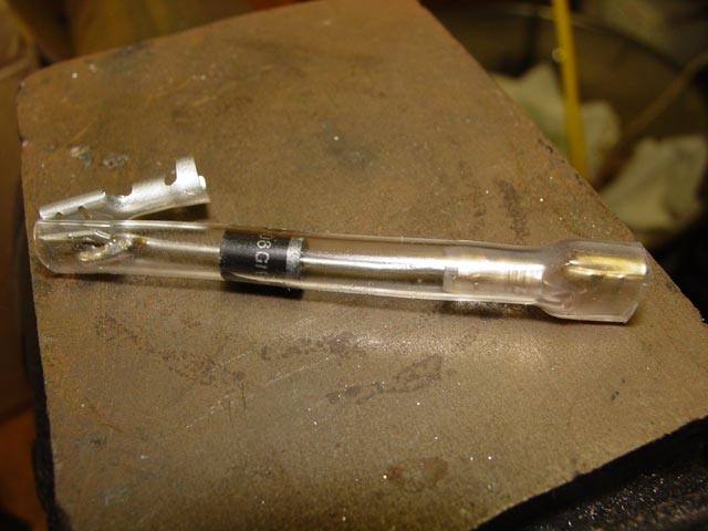
Here is the finished assembly. The second male connector goes to the harness, wire E1. The female blade terminal is the correct part to engage in the harness connector shell which then plugs in along the bottom of the CE panel. It will go in socket E1 on that connector.
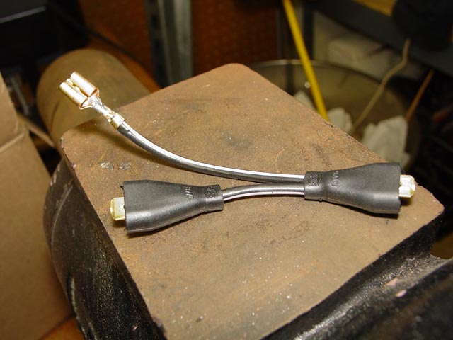
I had to make an additional wire which goes from the relay(end with vinyl boot) to socket #2 on the "B" harness connector shell.
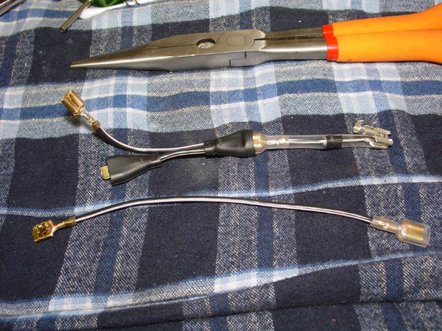
With that, I was ready to begin putting it all together. Here I had trimmed the new wires to approximate length.
This pic was taken after all soldering was complete. Note the connector with diode and vinyl boot is attached to the wire from the combo switch. The ground wire also has a female blade connector with vinyl boot(barely visible, far right). Also, the original wires from the harness were treated to heat-shrink insulation. One is visible behind the diode, the other is visible behind the ground wire, below connector "E".
At this point, all connectors were given a coat of Stabilant. I snapped my little "mini-harnesses" into the "B" and "E" connector shells and plugged them into the panel. I also connected the wire from the combo switch and the ground wire to the coil of the relay.
The "black with pink dots" wire is attached to the male connector on one leg of the "Y" harness. The middle connector on the "Y" harness is connected to the female connector on the diode. The yellow "B2" wire is connected to pin 30 on the relay. The wire coming off of connector B, position 2 is connected to the 87a(NC) pin on the relay. The tie-wrap goes through the hole in the mounting tab on the relay and around the CE panel mounting bracket. It's held very firmly, and doesn't want to move around at all.
At this point the Passing Flasher mod is complete. I'm going to insert a couple more details on the V1 installation here, since it ended up being part of the same project. Coming in from the right, you can see the black cable that leads to the main unit. The black ground wire is attached to the ground point near the center of the pic... it loops down behind the panel and comes back up alongside the power wire. The power distribution box is velcroed to the lamp control unit. Excess wire from the main unit and the remote display is looped, tie-wrapped, then tucked back behind the RJ-11 connectors
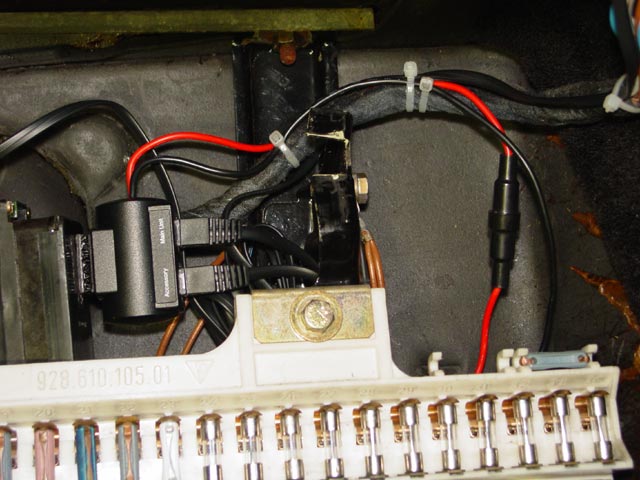
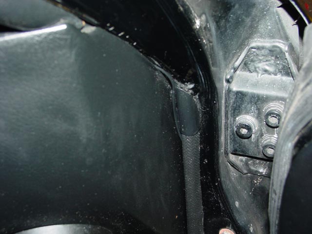
When I originally ran the wire from the main unit, I loosened the front of the headliner by removing the visors and the visor clips. I tucked the wire up in there, and brought it down the A-pillar by tucking it into the gap between the interior piece and the pillar itself. Once it's tucked in far enough, it falls into a void under the interior piece. It becomes visible for a couple inches as shown in the pic below, then tucks into the door beading and exits under the dash, above the package tray. At this point it is tie-wrapped to the harness as shown above.
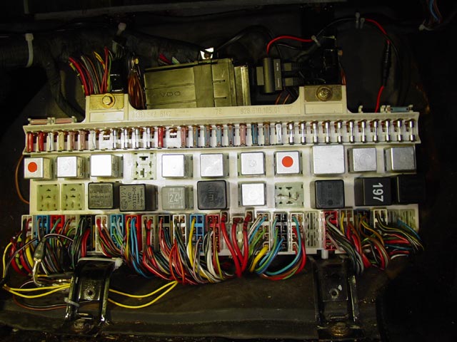
So here is an overview at the end of the day. I forgot to reinstall the defroster relay before taking this pic, but luckily I remembered before I buttoned everything up completely(it helped that it was laying on the floor under the CE panel cover). I still haven't figured out what the yellow wire leading to the console is for, but I expect to be digging through the console in the near future. Vee haff vays of getting answers...
So here is how my lights behave after the mod. When nothing is on, like when running around in the daytime, only the foglights flash:
When I have the headlights on, the foglights plus high beams flash:
When I have the foglights and headlights on, only the high beams flash.
When I have only the foglights on and I pull the lever, nothing happens, so there is no pic. This is a fairly rare scenario though, so I'm OK with it. Now I'm off to find some left-lane-hogs... shouldn't be too hard!


Parts List -- all parts from EagleDay except relay and diode. This is the final list of what was used on this project, though I did order a few odd terminals, like the right-angle blade connectors, etc.
- 1 ea. DPDT 12V relay
- 1 ea. Diode, Radio Shack P/N 276-1143(1N5402)
- 1 ea. 3-4707 Round pin terminal (comes in 10-pk)
- 2 ea. ECK-110 Insulated Male blade terminal (comes in 3-pk)
- 4 ea. ECK-120 Insulated Female Blade Terminal (comes in 3-pk)
- 2 ea. MCL-110 Female Blade Terminal (comes in 10-pk, could use surplus ECK-120 without boots)
- 1 ea. VWP-PG PiggyBack Blade Terminal (comes in 2-pk)
- 3 meters TAW-283225 Black/pink wire
- 1 meter TAW-3221165 Brown wire
- 1 ea. 1/4"(6mm) ring terminal