Well, I had gone through my central electric panel, refreshing all connections and adding Stabilant some time back. I had also refreshed the connections and added Stabilant on the central warn box under the dead pedal. I still had some minor gremlins, including an intermittent tail light warning, voltmeter reading way too low, and a rare problem where the oil pressure and level lights would stay on after the first start in the morning maybe one morning out of ten(gauge pegged as normal, no worries). Additionally, I knew my washer level light was out, and I suspected that the gauge illumination lights needed some attention since they were very dim. None of this was urgent, so it took me 2 years of ownership to finally dig in. I decided to replace all bulbs and clean all connections. I picked a long weekend to do this. I could have done the job in a day, but as it turned out I spent three hours on Sunday and six on Monday getting it done. Part of the reason I spent less time on Sunday was because I had to chase down some glue for the project, as you will see.
First order of business was to disconnect the battery ground strap, as with all electrical work as involved as this. Then I pulled off the horn pad. You have to just give it a very firm yank, pulling it straight off the wheel. The connector that you see hanging out of the bottom of the opening in the wheel attaches to the horn pad. Don't worry about it -- with the amount of force required to get the pad off, this connector will pop right off. If you do this with the battery still connected, expect the horn to make a lot of noise -- which will hopefully remind you to disconnect the battery.

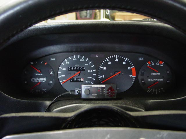
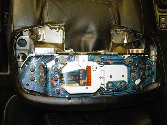
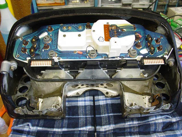
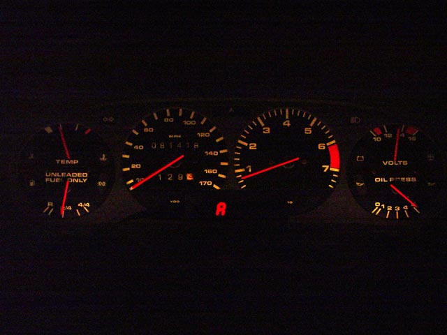
Here is a pic of the cluster before further disassembly. It's mostly here as a matter of historical interest -- occasionally I find myself wishing I had a pic of the cluster to help answer questions on the list -- so here it is.
Remove the 27mm nut from the steering shaft. DON'T use the steering lock to keep the wheel from turning as you do this, and don't attempt it with the wheel turned all the way to the left either. In the first scenario, you could snap your ignition lock. In the second scenario you could damage your steering rack. Have a helper hold the wheel for you, or tie one spoke of the wheel to something solid (maybe run the rope out the door and tie it to a post, beam, etc.)
Next, if this hasn't already been done on your car, mark the wheel position so you can get it back on in the same position it was in to begin with. If you use a center punch as I did, make the mark toward the inside of the shaft and away from the splines on the hub, so that any deformation of the metal will not interfere with reassembly.
With the wheel off, you can see the horn contact strip on the right, and the small plastic turn signal canceling nub on the left. Be very careful not to damage either one. When reassembling, use a light dab of grease on the contact and a thin film on the contact ring on the back of the hub. Whatever you do, don't use dielectric grease for this.

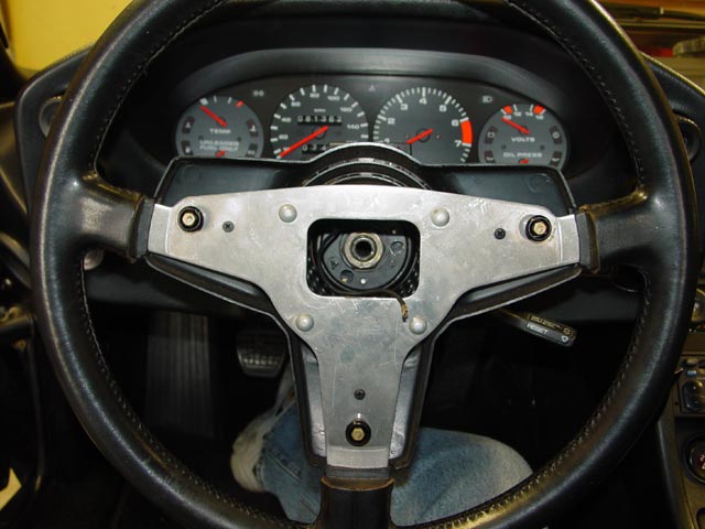
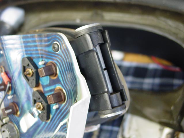
Next, pull the tilt lock down out of the way and raise the column/pod to the highest position.
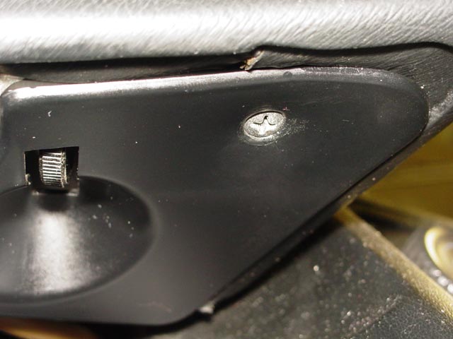
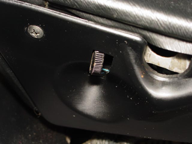
You will need to remove the lower trim panel from the pod. There are two screws for this -- one on the right...
...and one on the left. Be careful working it free. You need to maneuver it forward while disengaging the very fragile plastic tabs from the plastic piece that covers the lower half of the combo switch. I got lucky and didn't break anything, but it would be very easy to damage this piece on removal.
Next, remove the plastic piece that covers the lower half of the combo switch. There is one phillips screw(already removed in pic) and two M6 screws with 10mm heads. After that the plastic piece comes right out, with a little jockeying to get past the switch stalks. You will have to be very careful later on when you put these screws back. They should be snug but not tight enough to crack the plastic.
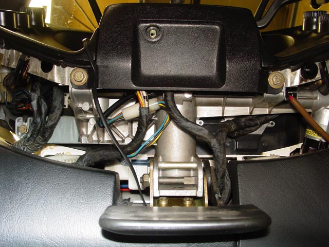
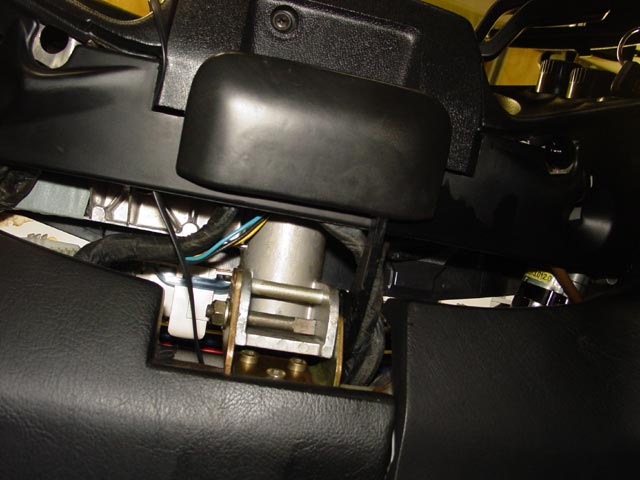
There are now only two M6 bolts holding the pod in place. The first one was visible in the last pic, but here is a better view. This one only needs to be loosened a few turns, because of the slotted bracket. Also note -- different years vary, but at least on the 78, one of the connectors to the cluster is visible from this perspective, at the bottom of the pic. It will have to be disconnected at some point before you pull the pod off.
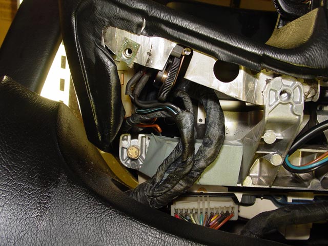
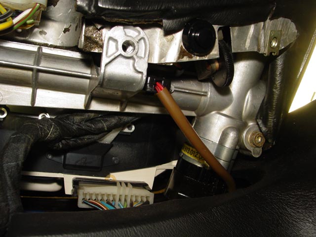
This allen screw that goes through a boss on the ignition switch is the last screw holding the pod in place. It needs to come all the way out. The second connector to the cluster is visible at the bottom of this pic. There was no chance of mixing these up on my car, but on some later cars the connectors are much closer to one another and you will need to mark them to make sure you know where they go.
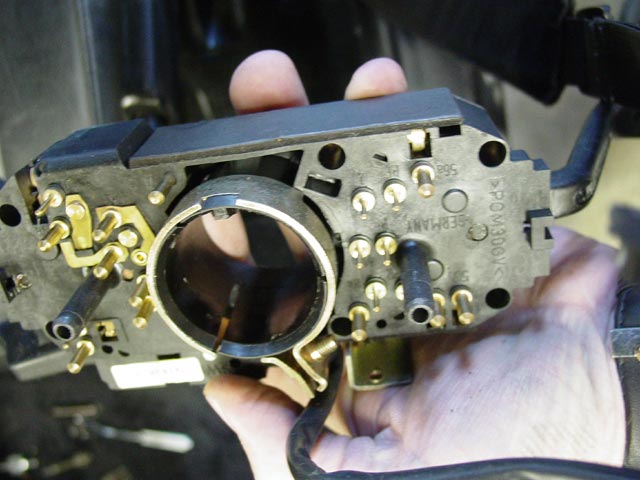
With all of the pod screws loose, you can remove the combo switch. This is the way it's oriented in the car, if you were looking up the steering column at the back of the switch. First, remove the two connectors that attach directly to the switch, then unplug the small pigtail that you can see running near my thumb. Then loosen the bolt that clamps it to the column. At this point you can lift the pod slightly and slide the switch off the column. When you first start wiggling the loosened pod around, the rubber ring around the ignition switch will pop out. Pay attention so you don't have to go chasing it later!
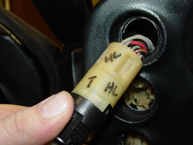
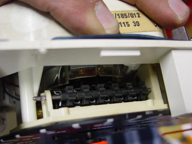
Next, you will want to pull all of the switches out of the pod. I have heard that the pod can be lifted off without doing this, but I didn't seem to have enough slack in the harness to do this. I marked each connector with three pieces of information:
- What the switch is(Headlight in this case)
- Which side is the top
- I drew a line across where the switch and connector meet to help line it up later(Not pictured).
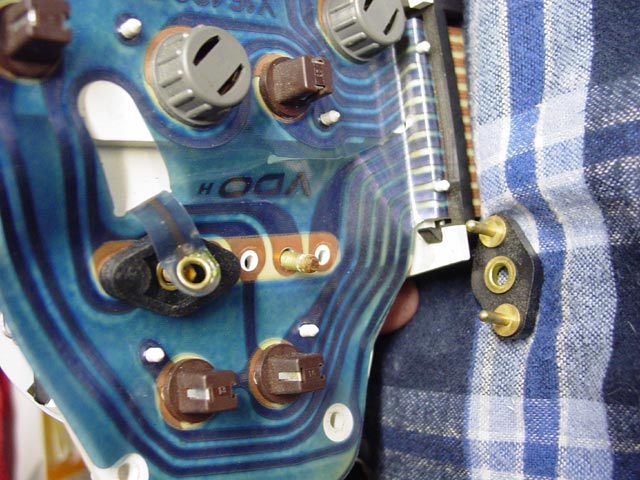
Also, at his point you will want to disconnect the two potentiometers for the gauge illumination and the wiper interval, and the intensive washer button. Pay attention to how they connect. It may not matter electrically, but it will be easier to get the connectors back on to their original locations. BTW, in my opinion the biggest PITA of the whole project was getting those potentiometers hooked back up. A long set of forceps/hemostat will help tremendously.
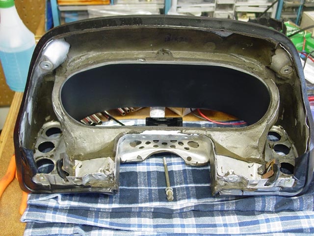
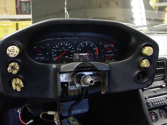
So, here is what the dash looks like without the pod....
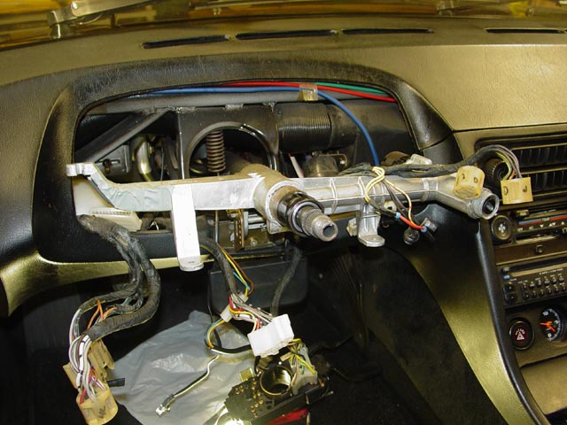
...and here is what the pod looks like without the dash.
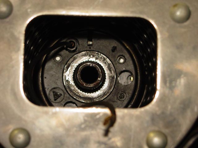
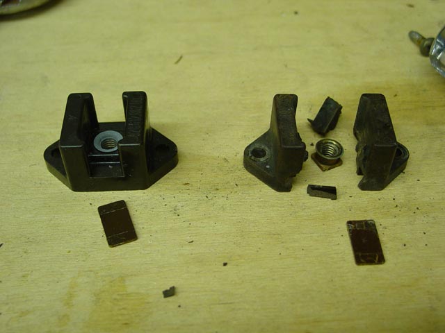
Note that on the ignition switch side, there is a small L-shaped piece of metal that mounts the pod to the ignition switch. I recommend that you find some way to mark it's orientation. I didn't and ended up spending more time than necessary trying to get it back into the right position on reassembly.Once you have it marked, remove the M6 bolt that goes through that piece, and remove the M6 bolt on the other side that was previously loosened. In my case the bolts were the same length, but if yours are not then pay attention to which is which. With those two bolts removed the cluster lifts right out of the pod. There are 4 rubber bushings attached to 4 hat-shaped metal pieces(pictured later) that you should make sure you keep track of. All 4 metal/rubber sets are the same, just don't lose them. If yours are hard or cracked you might want to replace them.
So, finally, I laid the cluster face-down on an old flannel sheet so I could get started working on it. Use towels, t-shirts, or anything else that suits you, just put something under it so you don't scratch the clear plastic. First, I carefully inspected the flexible PCB to make sure there were no cracks or damage to it. If it looked like it needed repair or replacement I wanted to know up front. The nine phillips screws that hold the cluster together are visible in this pic. Two at either end, two on the top edge, and three along the bottom edge.
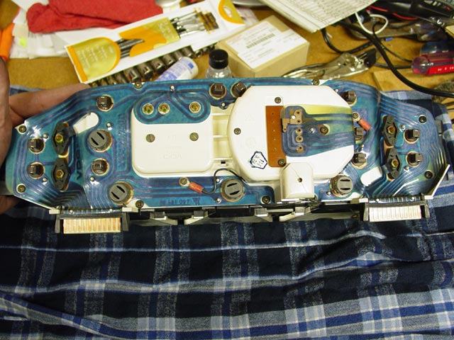
Once I removed the nine screws around the edge of the cluster, the front and back parts simply come apart. If this doesn't happen with just about zero effort, you've missed a screw or two. Later clusters may have fewer or more screws -- just be careful.
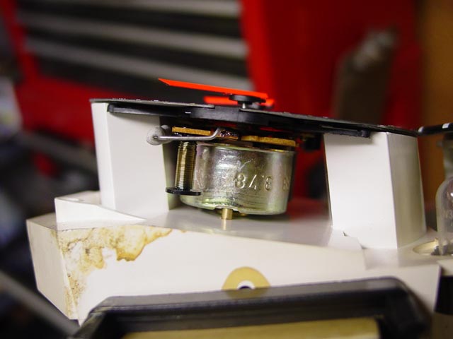
For the curious, I have included pictures of the innards of the cluster. First, let's go left-to-right across the bottom. The pic below is the fuel gauge.
This is the bottom of the speedo.
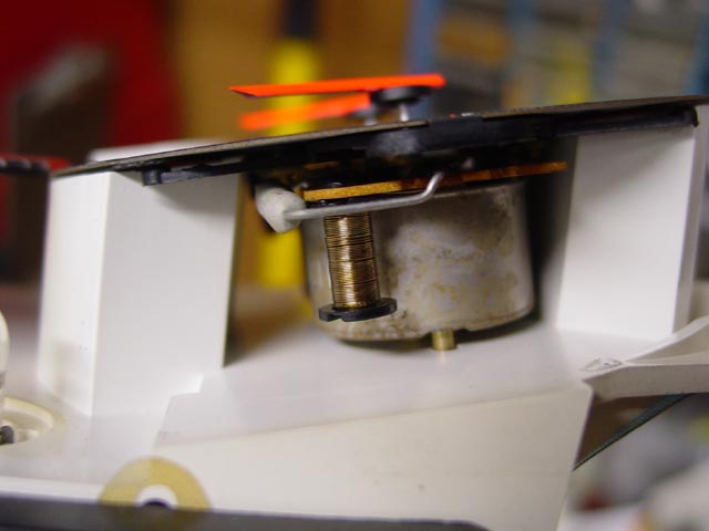
This is the bottom of the tach.
This is the oil gauge.
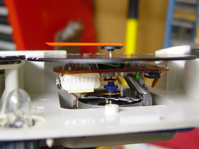
Now, left-to-right across the top. Here we have the temp gauge.
This is the top of the speedo.
Top of the tach.
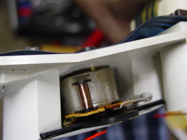
Finally, the top of the voltmeter. Alright, seems as good a place as any for this:
 Most people will tell you that the voltmeters in these cars are very inaccurate. I even went into this project having been told about the little trimpot that you see below on the voltmeter, which can be used to adjust the voltmeter to read the correct voltage, with the intention of adjusting it.
When I had the voltmeter out of the cluster, I connected it directly to a 12V battery and the reading was very, very close to what I read on my multimeter. Kind of hard to tell, how do you read 12.37 volts on the gauge?
I was surprised, so I put a couple of batteries in series to get 24V and used a potentiometer connected to the voltmeter to adjust it to read exactly on the 12V and 14V marks, as well as at my best guess where 13V should be between them. Compared to my fairly precise(Fluke) meter it was off by a hair less than 0.07 volts at 12 & 14, and it was off by about 0.11 at the 13v midpoint between them(which I eyeballed). I was surprised, since the idea that these gauges might drift over time seemed very plausible to me.So, I have a new opinion of these voltmeters, and that opinion is that they can be very, very accurate. I think that what so many people(including myself) see, the difference between the voltmeter and real battery voltage, is the result of deteriorated connections between the battery and the meter. This is only a "sample of one" at the moment, so if you have an opportunity to check your voltmeter, please let me know what your results are. You can email me at SharkLover@gmail.com or PM SharkSkin at RennList. FWIW, by the end of this project my voltmeter was reading within 0.15V of the voltage measured at the battery posts.
I'd recommend resisting the urge to mess with it, until you have any potential issues with grounds or other wiring sorted out. Otherwise, you may tweak the voltmeter today, only to find out later that it reads too high after you tighten up another connection somewhere!
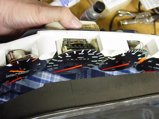
OK, got a little ahead of myself there. Here's how the gauges are removed.
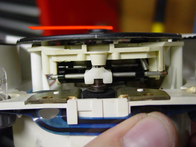
On each side of the cluster, there are two plastic caps each with a nut in the middle of it. The plastic caps are removed by first removing the nut, then pulling the plastic cap away from the cluster. I didn't need tools to pull any of them out. The stubborn ones came out just by grabbing firmly and sort of levering my finger pads against the cluster.The two pins on each of these caps engage female connectors on the back/inside of the gauges, and by compressing against the PCB they make the connection to the PCB. In this pic you can see both of the methods that are used to connect to the center stud; the upper(left) one uses a PCB trace with a grommet in it, the lower(right) one just sandwiches the PCB like the other two pins. The studs that these attach to are what mechanically holds the gauges into the cluster, so be careful once you have that second stud loose.
All of the pads on the PCB where these connections are made were cleaned by scrubbing with a pencil eraser until shiny. All pins, studs, and nuts were cleaned till shiny with a fine wire brush. Upon reassembly, all contact surfaces were coated with Stabilant, and I lightly re-swaged the grommets. The female connectors on the insides of the gauges were cleaned with round needle files while facing downwards over a shopvac crevice tool to suck any filings out.
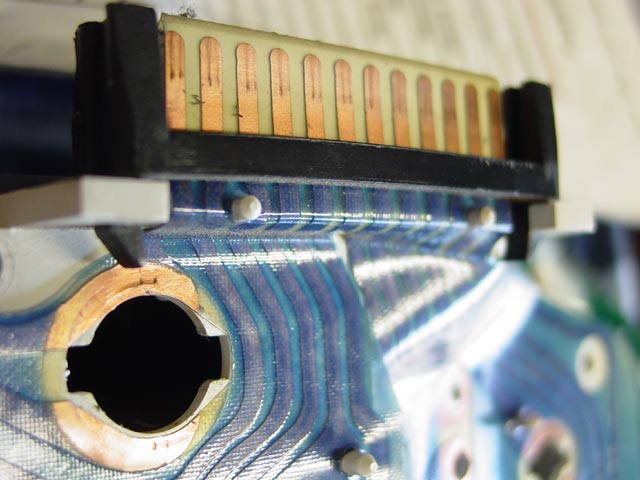
All of the bulb sockets and the edge connectors were scrubbed till shiny with a pencil eraser. Use a soft, fresh one, and when it loads up, you can clean it off by scrubbing on a rag or jeans. In this pic, there is still some eraser debris that needs to be cleaned off. The bulb holders were also cleaned thoroughly. I used a wire brush on the exposed part of the socket contact that connects to the PCB, and I used a needle file to clean the area where the bulb makes contact. I reassembled them with Stabilant on the PCB around the bulb socket, and some on the bulb contacts before putting them in the holders. If you think about it, that's 4 connections per bulb... worth a little insurance IMHO. I didn't coat the edge connectors till I was ready to put the pod back on the car.
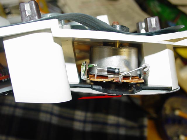
The connections on the back of the tach were a bit corroded, so I removed and wire-brushed the hardware and cleaned the PCB with the eraser. The two small ring terminals got the same treatment -- wire brush on hardware, eraser on PCB. I also wicked some Stabilant up into the area where the wire is crimped, and gave them a little extra crimp to break up any oxides between the wire strands. Also, there was a series of riveted connections on the back of the speedo that I put some Stabilant on. There wasn't much else I could do with them without turning this into a major project.
I didn't see any need to mess with the light channels that run from the bulbs to the front of the cluster, since the silver paint on them appeared to be in excellent condition. However, at some point in time a PO had upgraded the gauge illumination bulbs to 3W. No big deal, I had already planned to replace with 3W bulbs. But the black front shell of the cluster had melted somewhat over an unknown period of time.
When I saw the heat damage I decided to try some LED replacements. I was hoping they would be at least as bright as the bulbs without producing heat. Unfortunately they were useless, even after experimenting with frosting the end of the LED, adding makeshift reflectors, etc.
 So, a word of warning -- don't bother. If they are not bright enough to be of any use in a pitch-dark garage they will be less than useless out on the road, competing with glare off of other peoples' headlights, etc.
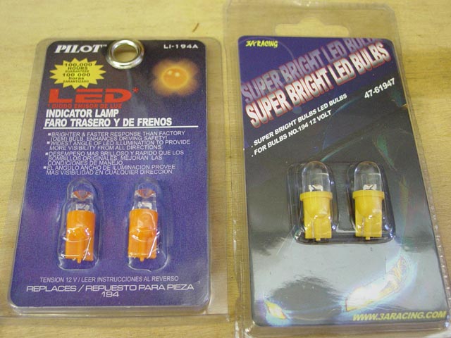
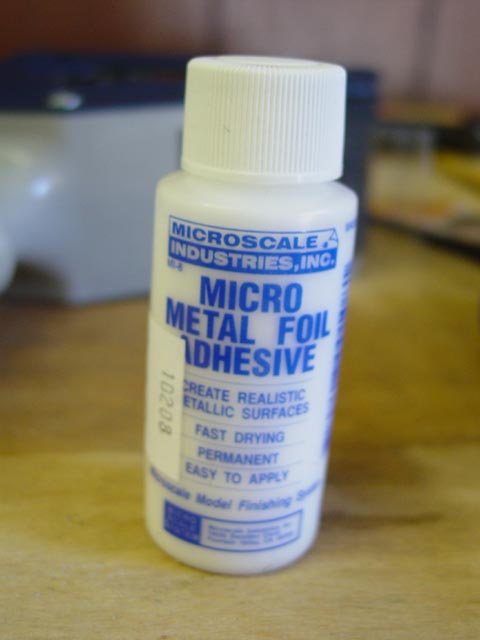
I found the solution to this at the local hobby shop. It's the adhesive that's used to glue metal foil on models, for example bumpers, trim, etc. It was about $3 for the smallest bottle.
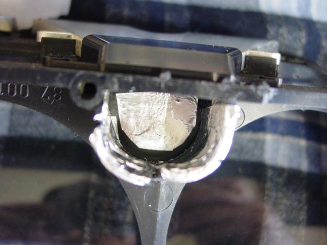
So the adhesive is applied to the dull side of the foil in a thin coat, and allowed to dry. I pre-cut my foil pieces before applying the adhesive. I had to use a few coats, because of the tendency for the adhesive to bead up. When the adhesive is dry, the foil is applied and burnished into place, starting at the center. I used a Q-Tip to press the foil into place. As you can see, I wasn't trying for a chrome-smooth finish or a perfect fit -- I only took a swipe at getting all of the dust out of this area, and I didn't cut the foil to exact size -- all I wanted was to make this area as reflective as reasonably possible, and maybe protect the black plastic from the heat of the bulb a little. Once this was done I was ready to put the cluster back together. Reverse of disassembly.... put those 9 phillips screws back in & tighten gently.
The next step was to put the pod up on the workbench, and clean the edges so it would all look clean, with no entrapped lint or dust when the cluster was installed.I checked the potentiometers out and they were fine, so I just cleaned up the terminals on them that the harness plugs into at this point.
These are the mounting bushings that I mentioned above. Make sure they are soft enough to isolate the cluster somewhat.
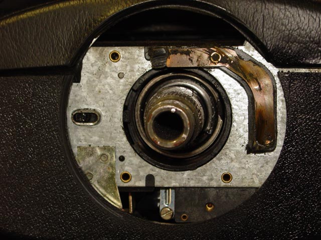
The next step is to position the cluster back in the pod. Do as I say, not as I do... the L-shaped bracket is NOT in the correct position for reassembly. Look above at the pic when I first pulled it out. It actually needs to go about 210� counterclockwise from the position shown below.

At about this time I coated the PCB edge connector with Stabilant, and also put some on the corresponding harness connectors. While I was at it, I put some on the potentiometer terminals and their corresponding harness connectors. I also cleaned all of the terminals on the pod switches as well as the terminals in the pod switch connectors. Then I placed the pod in position on the column, guiding the various connectors to where they belonged. Once I had the pod switch connectors going in more or less the right direction I connected the two rectangular connectors to the cluster.
Once I had the pod in position I was able to route all of the switch connectors to their proper locations. They stay put well enough if you just hook them over the edge of the switch opening in the pod, as you can see below. Also while the pod was loose, I connected up the potentiometers. Did I mention that it's a bitch to get the wires back on them?

I wire-brushed the connector pins on the back of the turn/combo switch and cleaned the terminals in the turn/combo switch connectors with a needle file. I then coated the terminals and pins on the combo switch with Stabilant and installed it. Don't forget to tighten the clamp that holds the switch on the column!
Next I coated all of the terminals on the switches and connectors with Stabilant and installed them, snapping them into place, then coating the bulb contacts in the switches with Stabilant and replacing the knobs as I went.
Don't worry about the fact that the cluster is not lined up with the pod at this point. As you position and snug things down to finger-tight you can nudge everything into alignment. Start with the two bolts that go through the bushings at the ends of the cluster. When those are finger-tight, the two holes for the M6 bolts down near the combo switch should be lined up, or they should line up with a gentle nudge. If not, look everything over very carefully. The only things likely to result in a misalignment here are an improperly aligned L-bracket near the ignition or bits of harness pinched between the cluster and the column. Don't tighten anything down until you see that the pod is resting squarely on all 4 supports.
Now you can position the plastic cover over the lower half of the combo switch, install the last two M6 bolts, and snug all 4 pod bolts down. They don't have to be very tight at all. Just enough that nothing moves around when you wiggle it, then another 1/4 turn.
While I was in an electron facilitatin' mood, I finally replaced the B+ terminal under the hood. I had intended to check and clean the terminal one day, put a wrench on it and it cracked. At that point It seemed as if it would hold together for a short while, so I left well enough alone and ordered a replacement -- which I had for a few weeks by the time I got around to replacing it.
It was holding together just fine, until I removed one of the screws that holds it to the body. At that point it disintegrated. I installed the new one on the left with Anti-Seize on the threads and Stabilant on all the terminals after I wire-brushed them.
The first thing I noticed when I had everything together and turned the ignition on was that the voltmeter was no longer reading 10V under these conditions. A very hopeful sign IMHO.

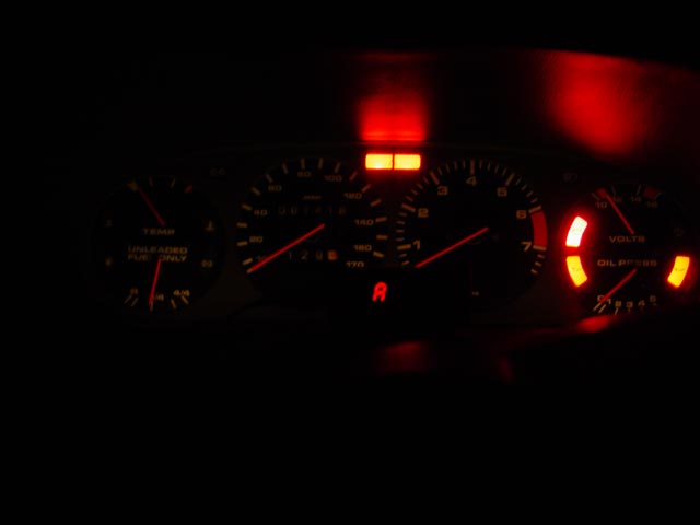
Here's the best news of all. Look at the voltmeter, and the tach. When I first start the car after it's been idle for a couple days, it sits right at 14V. Once the car has been running for a while, it settles down to where you see it now. When it was reading 14, I was measuring 14.15 directly at the posts on the battery. Also, as I write this(almost a month later) I have not seen the oil lights misbehave at all. Last, but not least, the gauge illumination is much brighter. It's easily 2 times brighter than it was before, or more -- and all of the bulbs had been working before. The pic below shows approximately how it looks to my eye, sitting in a dark garage. I had to doctor the photo some to make it match what I see more closely, because the camera doesn't do as well in low light as my eyes. But it's a big improvement, and after this project I found myself actually using the potentiometer to dim the gauge lights!

So all in all, I am very pleased with the results. It may not seem like much, but it seems that I have reached the point where fixing things on this car is a game of inches. This is a perfect example of how I may cut a broad swath through an area of potential problems and find only tiny, incremental improvements at the end. But they do add up, and it's a fun journey!