I already mentioned after installing my Devek radiator, I felt the need to upgrade the cooling fan on the front of my shark. Really my cooling problems were solved with the radiator, with the notable exception that the factory fan couldn't keep up with the heat load while idling on a hot day. In general I don't run into bumper-to-bumper traffic, but it does happen occasionally and I want to be prepared for the eventuality however rare it may be. When it happens around here there is often nothing at all you can do about it. I have been told by various people that the original fan puts out between 700 and 900 CFM... depending on who I talk to. I've measured the current draw, and it's about 17 amps. After considerable research I decided to replace it with a 16" Spal fan rated at 2300 CFM with a peak load of 19 amps. 26 years of progress in fan blade and motor efficiency....
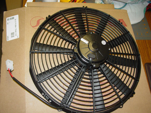
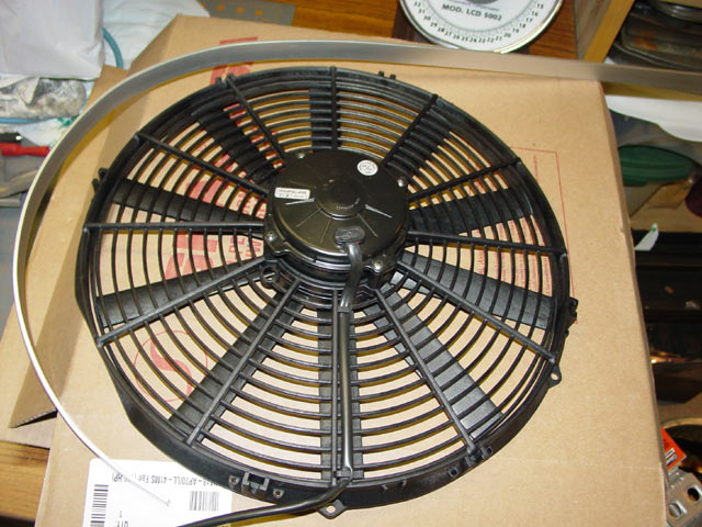
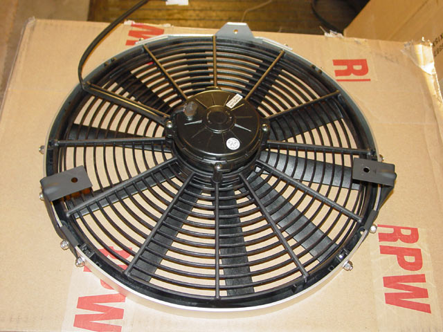
The first 16" Spal fan that I ordered arrived, and it was a "pull" type fan. Interestingly, the way it was wired, if I plugged it directly into the shark wiring harness it spun backwards, as a "push" type fan. Yikes! I first noticed this when I went to take my first look at how to install it. The vanes just looked like they were designed to pull. I ran straight 12V, + on the red wire to the fan, and sure enough it pulled air instead of pushing it. I researched the part number on the Spal website and verified that it was in fact a "pull" fan. I sent it back and when the replacement came I checked it out. It had airfoils that looked right for pushing, plus it had a ring around the tips of the blades(inside the shroud) that the other fan didn't. That ring is just visible at the 9:00 position on the fan in the pic below. Note that the "push" fan was wired so that it would "pull" when attached to the shark harness. Double-check any fan you put in! I swapped the wires in the fan connector and left the shark side alone.

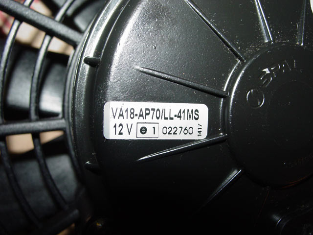
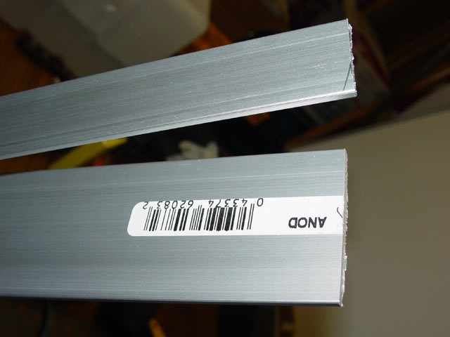
Here is the manufacturer's part number for the fan that I ended up using:
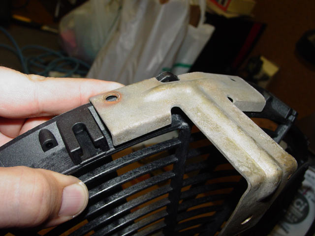
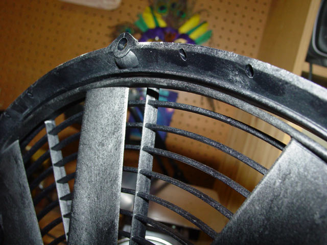
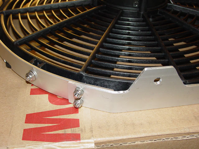
When the first fan arrived, the moment I pulled it out of the box I could tell that my plans for using the later mounting brackets and screwing them to the fan were shot. It turned out that the ideal position for the brackets was right about as shown, with the notch in the condenser side of the bracket hooked over the mounting eyes that protrude from the edge of the fan. This is with the flattened edges of the shroud oriented horizontally as you will see later. You can see through the near hole in the bracket that there is nothing there to attach to.
The Spal fan actually had an impressive array of mounting options. Here you can see the large(~1/4") eyelets, the T-slots, and the small #4 or so holes on either side of the T-slot. And there's no damn way I'm going to be able to fasten the brackets directly to the shroud...
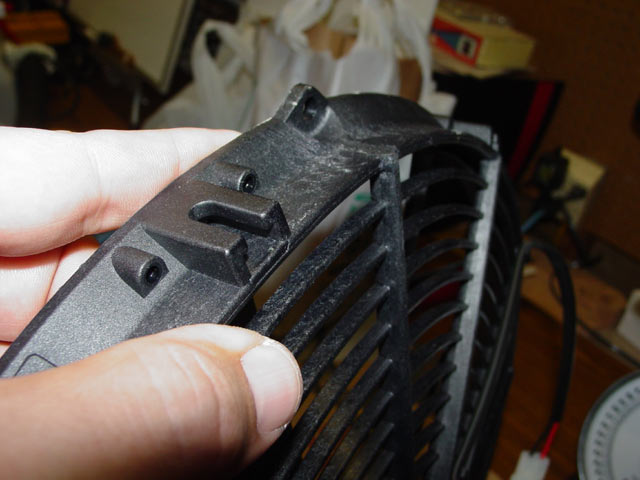
Nope, no way in hell. There's no room on the inside for any kind of fastener.

While waiting for the correct fan, I had been doing some brainstorming. I would make a hoop of aluminum and somehow extend the bottom end to provide a mounting tab to attach to the bottom mount. That was the tricky part; I had originally thought to have a tab welded on, but then I realized that it was going to be hard enough to get the hoop formed nicely enough to suit my taste.. Welding a tab on would still leave me with the problem of attaching the ends of the hoop neatly and at the correct dimension. In the end I decided to attach the ends of the hoop to a wider bottom plate that would extend far enough toward the front of the car that I could drill a mounting hole to use the original fastener. I would then carve off the excess metal. The entire process was to be engineered in vague terms, but implemented purely through cut-and-try. Quite frankly, this could be a great opportunity for a group buy kind of thing. These could be knocked out, welded rather than bolted, with improved mounting brackets for pretty cheap if there was enough interest. As it is though, expect to spend $20 and a weekend on duplicating this effort.
On project day, I went out to Orchard Supply Hardware and grabbed 5 feet of 1" x 1/8" and about a foot of 2"x1/8" anodized flatbar stock. I also grabbed much of the hardware that I needed. I picked up #8-32 and #10-32 flathead screws, washers and nylock nuts, all stainless. They only had the M6x16 Hex head screws and washers in Zinc, but lacking a comprehensive source for stainless hardware on weekends I picked up a set of these screws in zinc just to move ahead with the project.
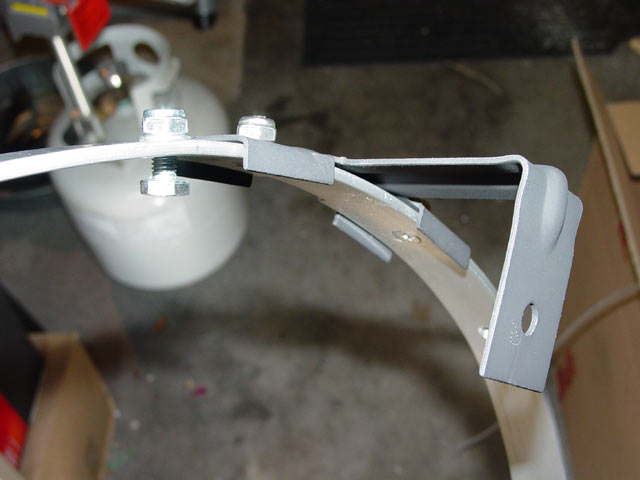
I began to form the curve in the hoop by wrapping the bar around a propane tank. The results were not as even as I would have liked and it wasn't quite the right size, so I spent a fair amount of time hand-working the metal into a smooth curve with the right radius. Here's a pic at about the halfway done point.
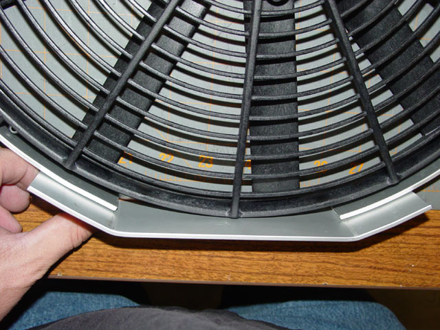
At last I had the hoop formed to the point where it fit smoothly and tightly around the fan shroud. At this point it is still a bit long; I will trim it later once I get the mounting worked out.
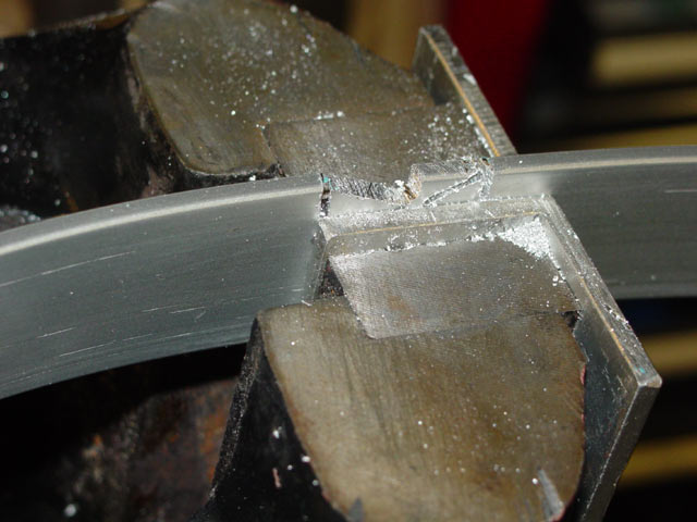
Next up, I had to cut and file notches in the hoop to clear the mounting eyes on the fan shroud. Well, I didn't HAVE to... I WANTED to. I didn't want to remove the eyes just in case my plan fell through and I needed them for plan B. It was real handy being able to rotate my vise on its side for this so I had a clear shot at the operation.
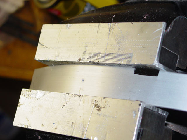
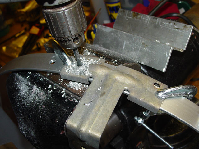
I marked and drilled the holes for the 6mm screws that would attach to the T-slots one or two at a time. I started at one end of the hoop as shown in this pic.
After each hole was drilled I would attach the hoop to the shroud and snug up all of the hardware... each time with another bolt. Then I would pull the hoop around tightly against the shroud and mark the next hole location. This, in a nutshell, is how I achieved such a smooth look on the whole assembly without having waves in the aluminum at each fastener or having gaps between the aluminum and the shroud midway between fasteners.
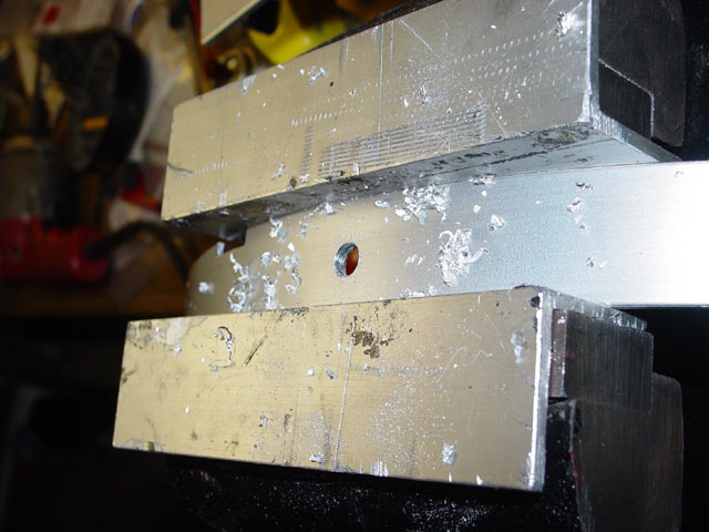
Here's a look at one of the bolts in a T-slot. Again, this is a zinc plated screw... only used for lining things up while building. There are a total of 6 M6 screws around the circumference of the fan.
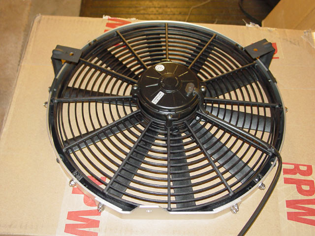
I cut the hoop back so that the ends terminated at the plane identified by the flat spot on the bottom of the fan. The flat spot is visible at the 9:00 position in the first pic on the page. The bottom sort of defined itself as that flat spot 90° CW around the circumference of the fan from the electrical connector, as I didn't want to modify the harness in any way(well, not for this). While fitting this piece all of the screws in the T-slots were snug. I bent the bottom bracket to fit tight against the flat on the fan as well as the ends of the hoop, allowing extra length so there would be room for the locknuts and some screw threads which I knew would protrude where the bottom bracket attached to the hoop. This will be more apparent in later pics.
Having carefully measured, marked and center-punched the bottom bracket, I positioned it carefully against the hoop and clamped it in place. By drilling both pieces at the same time I am ensuring that the holes line up properly.

After drilling, I pulled the hoop off of the fan for the umpteenth time, counter-sunk the holes, and mounted the bottom bracket to the hoop. Here it is assembled, ready to move to the next step.
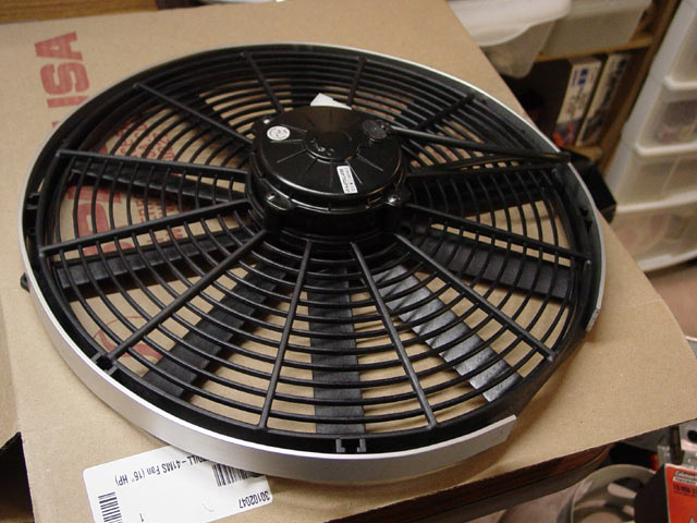
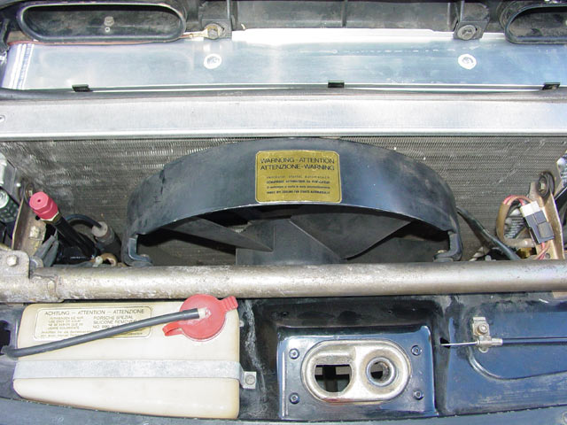
So, the time has finally come to pull the old fan out. Here's one last look at it...
With the old fan out of the way, I positioned the new fan and bracket against the front of the condenser. I marked the locations for the steel brackets. As it turned out, the final mounting locations for the brackets were not quite symmetrical, so I'm glad I did it this way. When I first eyeballed it I hadn't accounted for the extra 1/8" or so of aluminum under the fan, and the 1/8" or so of rubber donut under that. Anyway, I used the same method of getting holes to line up... clamp and drill.
Then I countersunk the holes on the inside of the hoop and mounted up the brackets. The picture below was taken before I realized that it would be impossible to place the hoop over the shroud with the brackets mounted; I had to trim off the tabs that hang over the edge of the hoop on the condenser side, then repaint them again, let them dry...

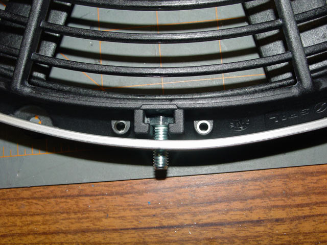
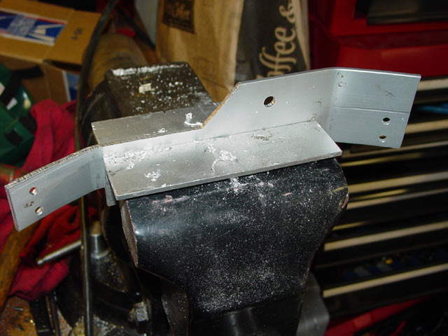
While the paint was drying on the top brackets, I set about cleaning up the bottom bracket. I had performed a rough cut on it as you see in the pic below so that it would clear the speed nut on the center strut of my front grill. At this point I had also reassembled it and marked and drilled the bottom mounting hole, and scribed some lines so that I could cut it down to match the width of the hoop. I cut more material off of the whole top(front) of the bottom bracket, leaving just enough so that it would completely cover the large rubber washer on the bottom side.
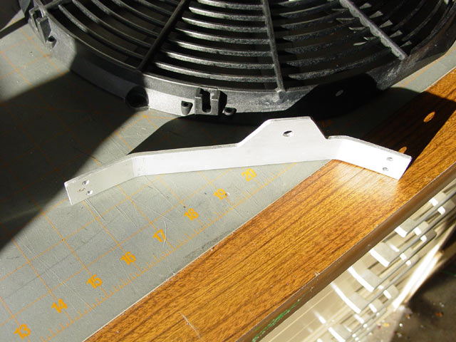
Here is the bottom bracket finished, shaped and cleaned up... ready for final assembly.
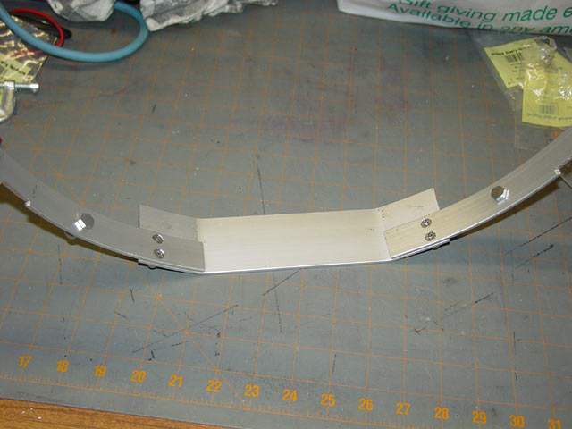
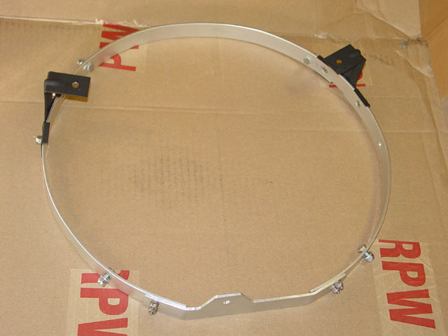
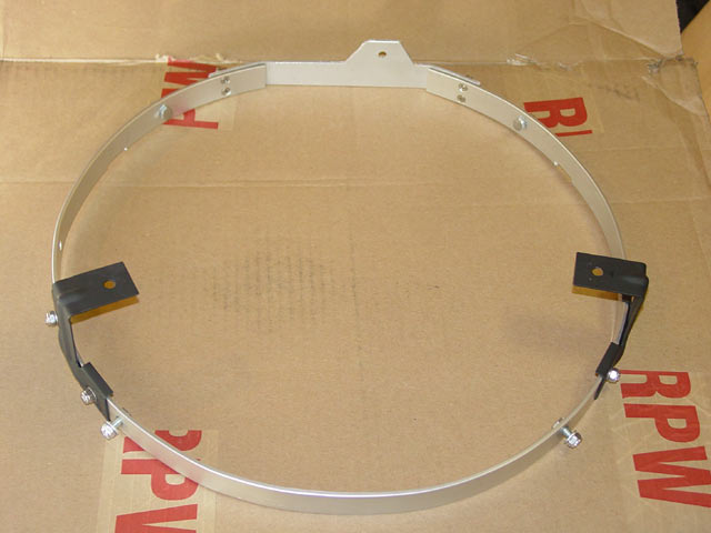
Below are a couple of pics of the entire finished mounting bracket assembly.
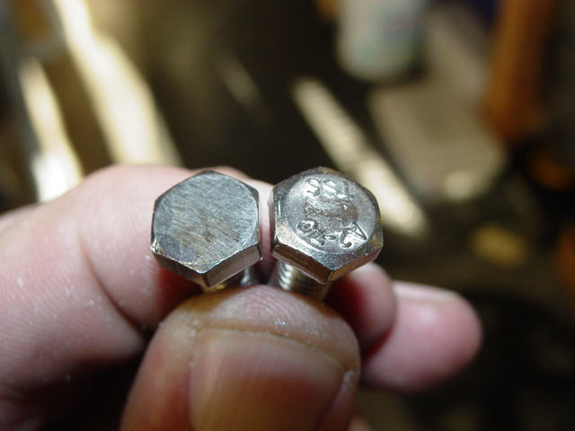
I had to file down the screw heads to get them to slip easily into the T-slots. I had to do this to both the zinc plated screws I used for fabrication and the stainless screws I used for final assembly. Oh well, that's the price I pay for not having the time to go to Olander and get the right hardware before I started.
Here is the final assembly ready to drop into the car.
And a closer look at the finished bottom bracket and bracket-to-hoop mounting.
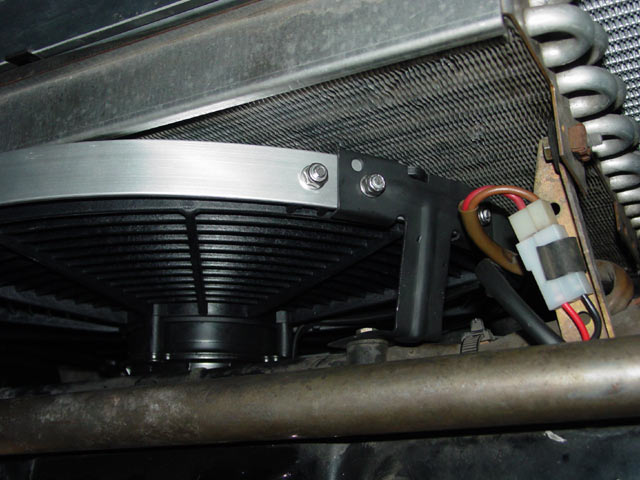
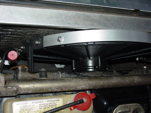
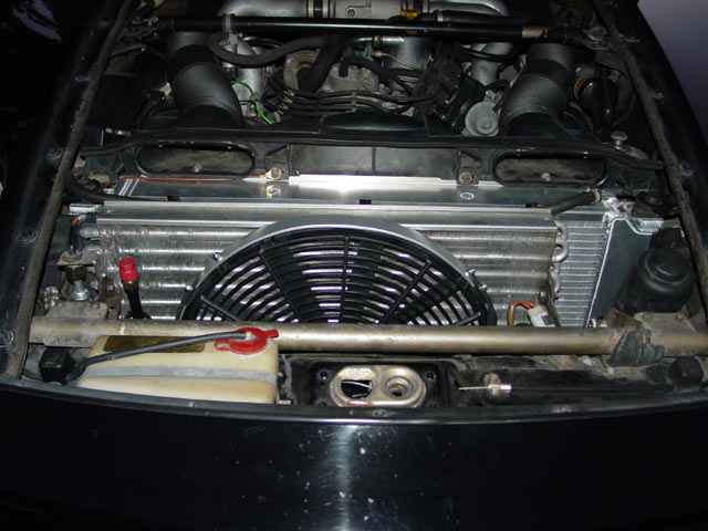
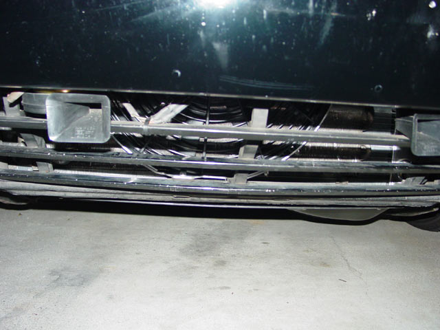
And finally, some pics of the fan installed in the car. In the last of these four pics, you can just make out the thick rubber washer that the bottom bracket sits on. While I had the fan out I made a stab at straightening the fins on the condenser, straightening maybe 75% of the fins that needed it. There were some near the top passenger side that were pretty mashed, and I've saved that project for a rainy day. Also, while the fan was out I thoroughly cleaned the condenser, getting to all I could reach with a 1" paint brush and Simple Green. I can't say if it works better, but it sure looks better!
All in all, it was a pretty long, involved process. I could have finished in an afternoon if I wasn't so particular about how it would look but... well, I'm happy with it.
On the first hot day after installing the fan, I again blocked off the airflow through the radiator and condenser with a piece of cardboard and unplugged the fan. Once the car reached about 95°C I removed the cardboard, plugged in the fan and closed the hood. By the time I made it back to the temp gauge the needle had dropped considerably and in under a minute the gauge was in its usual middle position and the fan switched off(70°C fan switch). Mission accomplished... no need to fear the rare traffic jam on hot days! Also FWIW, the entire fan assembly weighed in at 7 pounds 10 oz. compared to the original which was 9 pounds 12 ounces. Allowing for 2 oz. of grime on the old fan, that's a 2 lb weight savings!
