The Climate Control System
One of the systems in our cars that seems to constantly gives us fits, chills, and the sweats is this one. The HVAC system consists of several items - some of which are not readily visible to the casual observer. Sometimes the system gets 'confused' and will do it's best to make you comfortable - but when something goes out of whack it is not successful - and you pay!
This is a very basic layout of the system (as well as my limited understanding!) and it's components. Hopefully this will help someone out in their time of need. If you find that something needs to be changed/updated - please let me know! Here we go!!!
The Climate Control system consists of electrical and pneumatic items which try to work together to control the cabin temperature. The electrical items are -
In addition, the Solenoid Block controls vacuum to 5 different Pneumatic Actuators which in turn are positioned depending on the systems output/demand (i.e. what you want the system to do).
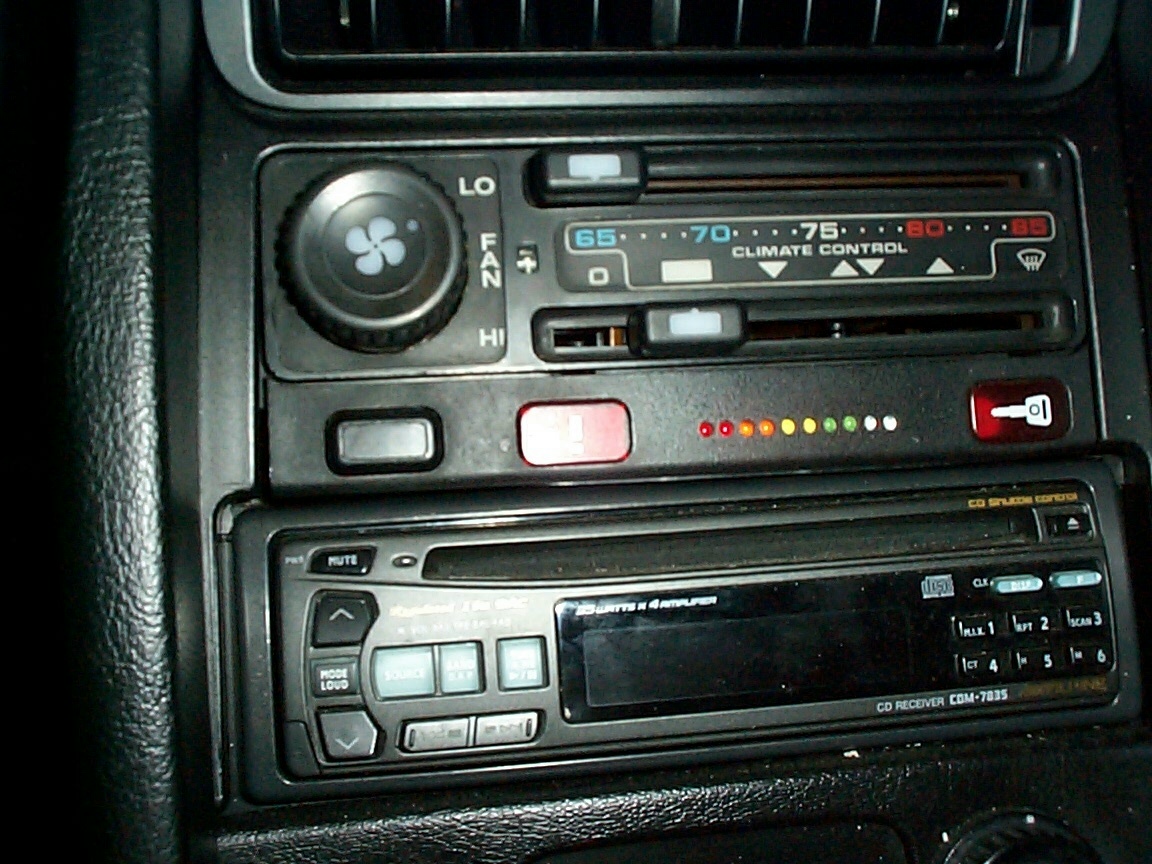
The HVAC Control Unit
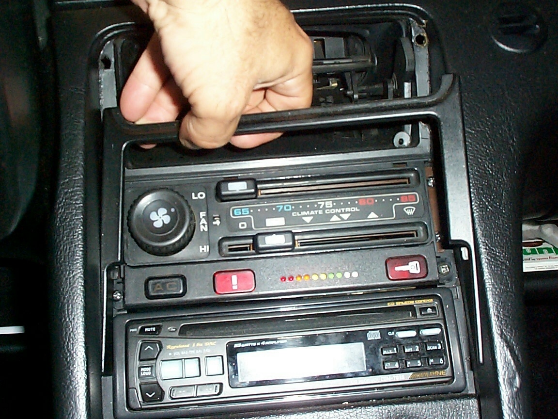
This is the part in the center console that you try with all your might to get the cabin cool in the summer (or warm in the winter). To Control Unit is held in place by the Center Vent, a trim Bezel, the Central Alarm (held in by 2 screws), and finally 4 screws. I prefer to remove the Front Seats in order to easily access the carpeted side panels. To get started, remove the Center Vent by using a putty knife (or small standard screw driver as shown). Gently pry the Center Vent out of the recesses.

Carefully remove the trim bezel (it should come out very easily with a bit of gentle twisting).
Next, remove the two screws holding the Central Alarm panel in the Center Console. Gently pull the Central Alarm panel out and disconnect the 2 electrical connectors - one for the AC Switch and the other for the Central Locking/Seat Belt Warning Lights.

Now the HVAC Control Unit comes next. Remove the 4 phillips screws holding it in place. Carefully pull the control Unit forward enough to wiggle a small standard screwdriver in and pop off the electrical connector on the Drivers side. Finally, disconnect the plug-in on the Passenger side. Pull the Control Unit out all of the way --- Tah Dah! VICTORY!!!
(picture to come)
Disassembly and Cleaning
After several years of driving/dirt/smoke, your unit may need to be cleaned to ensure proper operation (or your light bulb may be burned out like mine was!!!). This is an easy task - all you need for cleaning is a pencil eraser (or you can use a Q-Tip and some rubbing Alcohol). To disassemble start by removing the covers from the Control Unit. The cases will easily come apart once you remove the screws which attach the covers to the PC Board. After you get the covers off - turn the unit upside down so that you can see the PC Board circuit traces. Get out you trusty pencil eraser and 'go to town' on it. Make all of the contact areas nice and shiny.
Now for the light bulb (if your light is fine - skip this mudane part). Be sure that the Unit is right side up in front of you. You should be able to locate a red and brown pair of wires which lead into the belly of the Unit. Using a small pair of needle nose pliers, gently twist and remove the bulb holder from its' socket. Once the bulb holder is free, you can replace the bulb.
Insert the bulb holder back into the socket. Pay close attention to the 'flats' on the socket and holder making sure that they match up.
(pictures to come)
ADVANCED TIPS
Now, if you own a Volt-Ohm-Meter (VOM) [easy to operate and a fairly in-expensive purchase at Radio Shack], you can check out the electrical components on the PC Board (hey, you're already in here now - why not apply the WYAIT rule? Takes just a few minutes!!!).
The MAX Heating and Max Cooling functions are controlled by a pair of micro switches. These can be easily checked for proper operation by using the Ohm Meter selection on the VOM. Place one lead on each end contact of the switch and check for NO continuity (i.e. infinite resistance value). Then position the HVAC temperature selector such that it contacts the micro switch - causing it actuate. You should hear a 'click', as well as see your Ohm Meter go to a short circuit condition (i.e. little to no resistance value).
The Temperature Select function is actually done by positioning a potentiometer located in the center of the HVAC Unit PC Board. By connecting your VOM meter between the points associated with the pot pins, you can monitor the pot as you adjust the temperature select.
(pictures to come)
Positioner/Controller
(pictures to come)
This is a part that you cannot see physically (unless you look up under the Driver's Side on the dash). This item works with the Control Unit to position flaps associated with the heat Exchanger behind the dash.
In order to properly access this unit, you either have to be a contorsionist - or remove the Instrument POD. Since I'm pretty stiff, I choose the later. As it turns out - this was a good idea since the 'adjusting arm' is located behind the ducting for the air flow to the driver's door (which has a convenient piece already fitted in just for this sorta thing - imagine that!). This 'adjusting arm' passes thru the Heat Exchanger and positions 2 arms located behind the left side of the Glove box. These arms in turn position flaps which direct air flow from the blower across the heating coil and air conditioner coil in unison to obtain a mixed temperature air flow out of the system vents (or hot air out of the defroster when the lower switch on the HVAC Unit is placed in the Defrost mode).
Interior/Exterior Air Temperature Sensors
The HVAC Control Unit uses these sensors as inputs to determine how to direct signal output to the rest of the components in the HVAC system. TIP: The HVAC Control Unit will 'fail' to a default position of 'ice cold' at the far left temperature position, and 'blazing hot' on any other position if the Exterior Air Temperature Sensor becomes disconnected from the system.
Interior Air Temperature Sensor -
This rascal is located behind the Darth Vader looking piece on the center console. The sensor works by using a small fan to draw thru interior air thru a sensor, which in turns feeds this signal to the HVAC head loop. I was able to get the sensor out only after removing the Center Console. If the small fan is making a humming noise, you may be able to clean the unit using the following steps. You can also check for proper sensor operation by using a blow dryer (or heat gun).
This is what the Interior Air Temperature Sensor looks like out of the Center Console.
Disassembly is pretty easy. I removed a few spring clips to seperate the housings from each other. Note that even if you can 'snake' a Q-Tip inside the Darth Vader piece on the front of the dash, you will probably be obstructed by the fan blades themselves before you actually get any real cleaning done.
Next, remove the smalle motor/fan assembly from the remaining housing. Be certain to note where/how the wires fit into the housing. All disassembled below.
Now that the fan is out, you can clean it up really good. I used a Q-Tip dipped in rubbing alcohol to remove 14 years worth of gunk and hair (ouch!).
Ahhh, all clean now.
Reassembly is reverse of disassembly (don't ya just hate that in the manuals???). Actually, this is pretty straight forward (you did pay close attention on how the wires were routed - didn't you???)
Exterior Air Temperature Sensor
This item is located behind the Driver's side wheel well forward panel. It is spliced in between 2 pieces of ducting which make up the Alternator Cooling Air flow. Sometimes thru the everyday normal driving, this sensor can become disonnected from the main wiring (like mine was) - thus leaving the HVAC Controller scratchin' it's head.
To properly access this little gem, you will need to raise the vehicle and remove the Drivers Front Wheel. Raise the Headlights so as to not chance scratching them, then remove the forward splach guard. The picture above is what you should find behind the splash guard - hopefully with the wiring attached (unlike mine).
Below is a picture of what the Exterior Air Temperature Sensor looks like out of the Alternator Cooling Air hose.
You can easily check this sensor for proper operation by using a blow dryer (or heat gun) - [Hey, be careful here - no burns okay???]. Connect you VOM meter (on the Ohm function) and check that the sensor reads a resistance value. Use a hair dryer to blow on the sensor and check the resistance value - the value should change appreciably. If not, you can order a new one easily by picking up the phone.
Blower
Ahhh yes, the Blower. An easy item to overlook - but yet a real pain in the rear to get to. The blower is located under the Passenger side of the hood. Should you have a need to access the blower, you may have to pull the bonnet (aka engine hood). I realized that this can be a difficult task once I got into it. Removing a >$2000 new component can be intimidating at best! Since there is already some good info already out there on this - check out Tony's page for extra stuff here.
Resistor Pack
The Resistor Pack is located also under the bonnet for ease of access (yeah...right!). Again, I'll default to Tony.
Pneaumatic Actuators
More on these later....
Hope the above helps shed some light (or cool air) on the subject.


