This was a three-for-one.
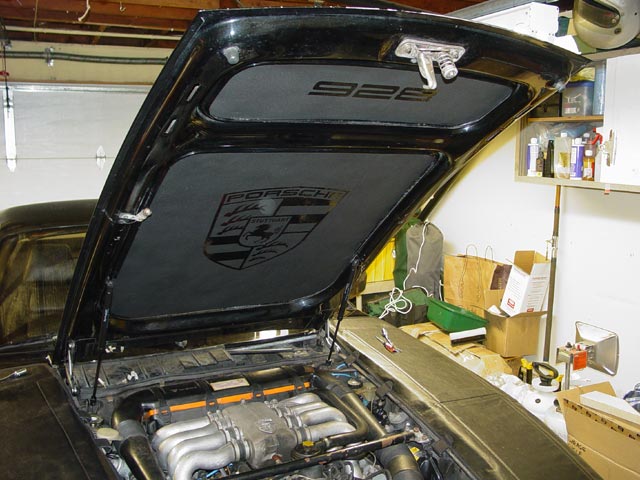
 The hoodpad from 928 Motorsports that I had installed around 2005 was getting pretty ratty, and I had been wanting to find the time to address it. The blower did not seem to be moving as much air as what I've encountered in other 928s, and I figured it was just getting old. When I determined that my AC expansion valve wasn't metering properly, I decided that since all three tasks would be easier with the hood off it was time to go in and work on all three at the same time, plus I would re-seal the recirc box while I was in there.
First I took my car to a local AC shop and had the system evacuated. I'll get credit for that freon later, when he recharges it without billing me for freon. He loaned me a vacuum pump that I could keep during the 2 weeks that both my work and his business were shut down. I bought a new expansion valve and a used HVAC blower, as well as a hood liner from Rob Budd and went to work. I scribed the location of the hinges on the hood prior to removal, but I ended up readjusting he hood to suit myself in the end. I laid the hood out on a couple layers of cardboard covered with some old flannel sheets.
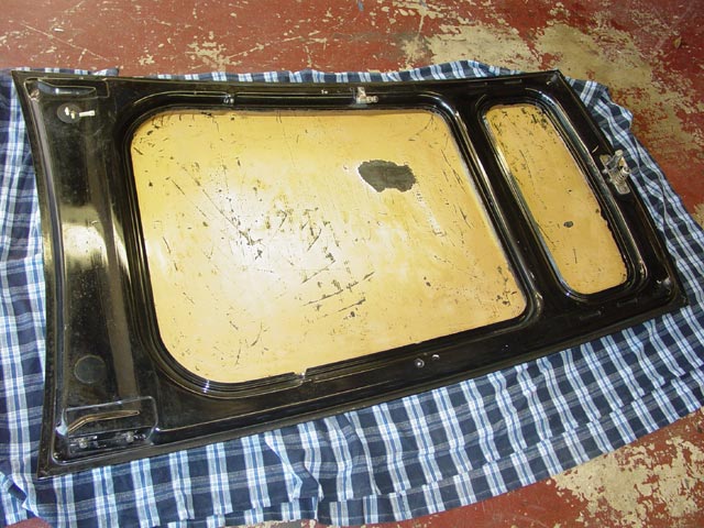
Here is the front edge of the Motorsports hoodliner. It lasted maybe 3-1/2 years, and was one of the better options available when I bought it. Over time though, the 3M #77 adhesive gave way, as did the hoodliner itself.
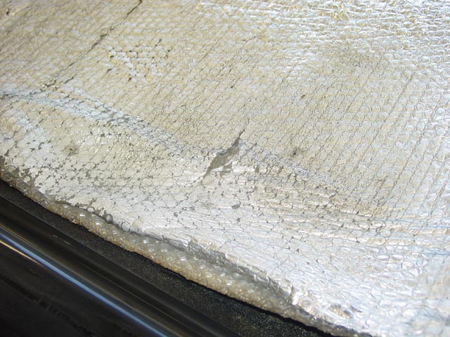
The nose piece was holding together, but it never sees as much heat as the main liner since it is in front of the radiator.
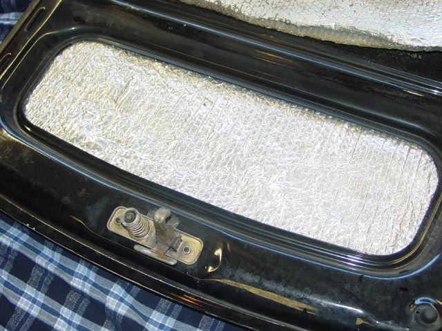
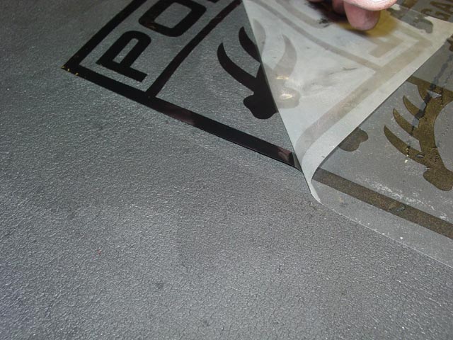
The hood pad came off very easily, further highlighting how unsuitable the 3M #77 is for the application.
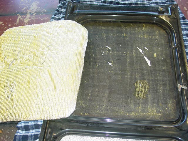
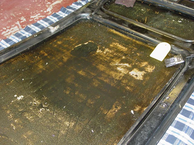
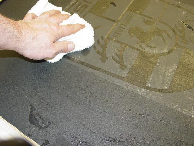
The old adhesive that was under the 3M #77 didn't want to let go easily. It took several hours of soaking in mineral spirits scraping with a plastic blade, and scrubbing to get it clean. The yellowish patch is an area that is clean. I used the paint brush to keep all of the adhesive wet with mineral spirits while I did other things. If you want to skip ahead to further work on the hood pad, click this link.
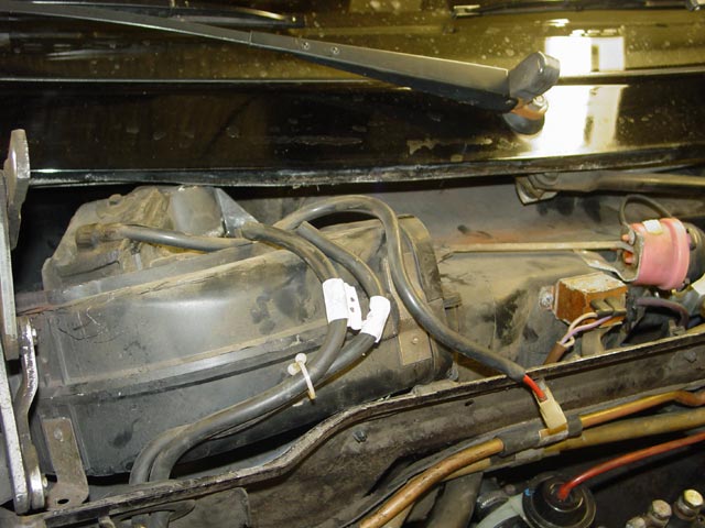
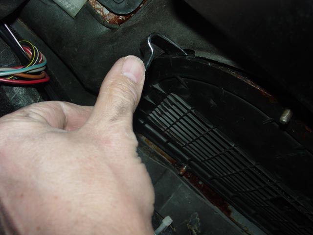
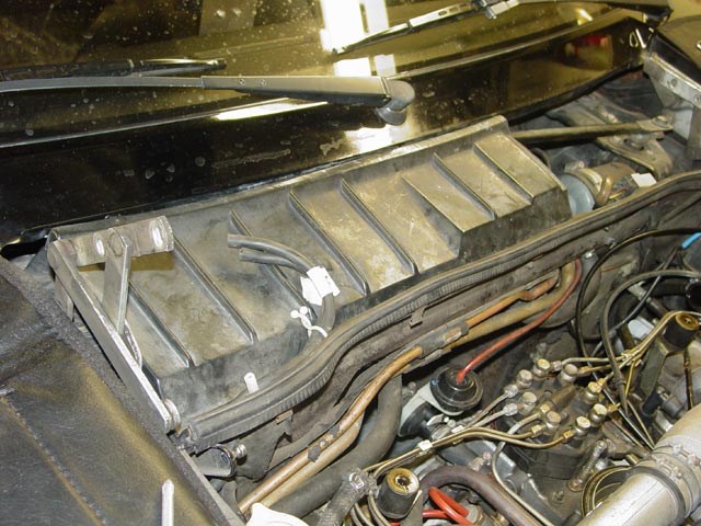
Once the hood was off and soaking, I pulled off the plastic piece that covers the cowl area and unplugged the blower motor.
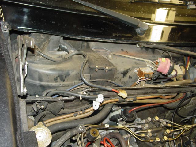
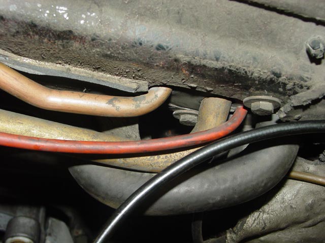
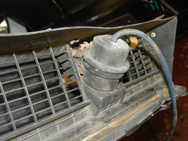
After thinking about it for a minute, I decided to go ahead on the AC. I had the hood laid out in the middle of the garage floor, and resealing the recirc box was going to involve disconnecting the battery and dismounting the fuse panel. The weather was threatening rain, and I didn't want my car stuck in the driveway in the rain with the blower out, hood off, and immobile. Here is the old expansion valve. I had installed it in July '04, and I guess that it never worked right, which was why the system never cooled quite like I felt it should. I was getting suction pressure in the high-20s.
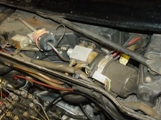
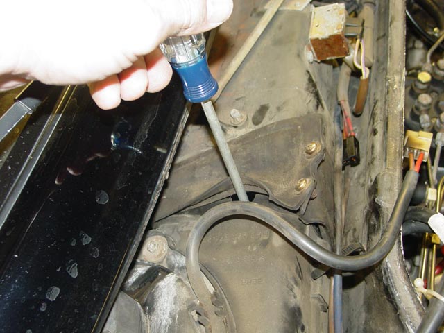
I removed the retaining clip holding the hardlines to the firewall. This is at the far left of the pic above. It is held with a single 6mm screw.
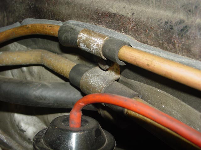
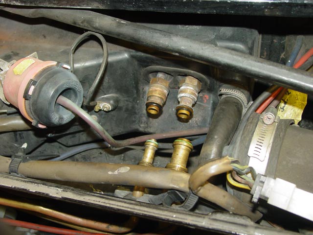
Next, I removed these two 6mm bolts that hold the plate and rubber grommet where the hardlines and heater hoses penetrate the firewall.
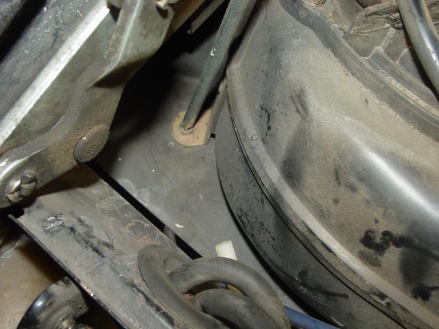
Removing the expansion valve was a piece of cake. I was able to get a large wrench in to counterhold the valve while I broke the lines free, and it came right out while pulling the hardlines forward. Having now done this job with the hood on and with the hood off, I can say it is much, much easier with the hood off.
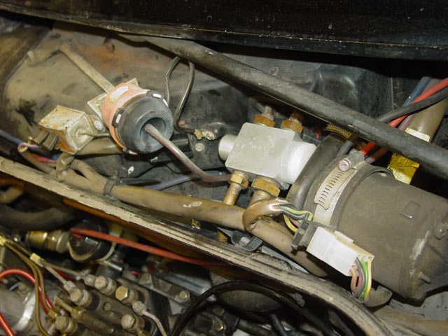
Putting the new valve in was also very easy. I collected oil from the old expansion valve with a q-tip and used it to oil the new o-rings, being very careful to avoid getting lint on the o-rings. The hardest part of putting things back together was getting the bottom bolt started on the bulkhead plate.
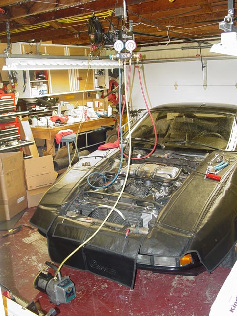
Between cleaning off the hood and swapping out the expansion valve, I had eaten up the afternoon so I called it quits and vacuumed down the system overnight. I turned off the pump and closed the shutoff valve at the pump the next morning while I made coffee, ate breakfast, did a little surfing... The gauge didn't move in ~2 hours so I counted it a success and moved on. Update: When I went to have the system charged, it was about a month after pumping it down to ~30in/Hg. At that time, when we hooked up the gauges, the vacuum was at ~26in/Hg. Considering that part of the difference was due to a short section of test hose being at atmosphere when connected, this was very impressive IMHO.
The blower is mounted in place on top of the recirc box with three screws. Here is the first one, directly under the hood hinge.
The second screw is inside the duct. Be careful not to drop it, it could take you a while to find it. I'll get to the third screw in a minute. I've heard that later cars use hex head screws that require an 8mm socket, but all of mine were phillips. I don't know when they changed over, but you could just look at the one under the hood hinge to find out before you start the project.
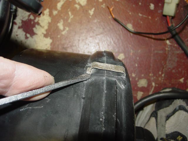
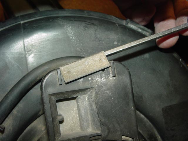
The boot between the blower and the HVAC box had to come off. It's pretty straightforward.
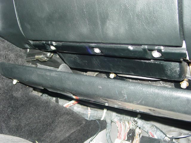
The package tray had to come out. There is one nut at the far left of the pic, two are visible between the tray and the glovebox, and the fourth is at the far right end of the tray, near the kick panel.
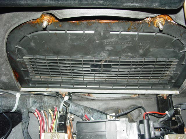
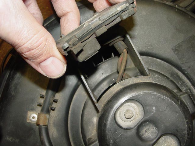
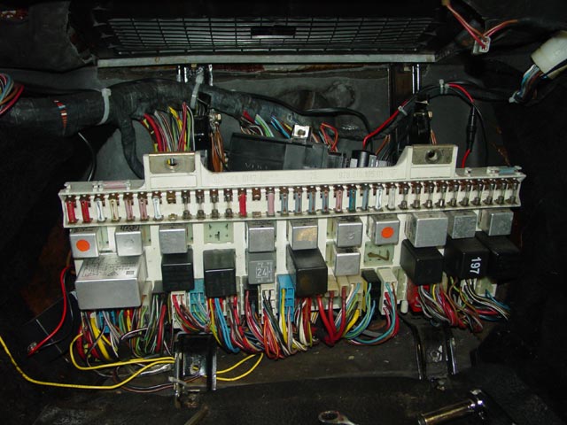
Next, I removed the floormats, the Central Electric panel cover, and the lower(stationary) wooden piece of the CE panel cover. This large D-shaped plastic piece is the air intake and recirculation door, and is also the box that the blower mounts on top of.
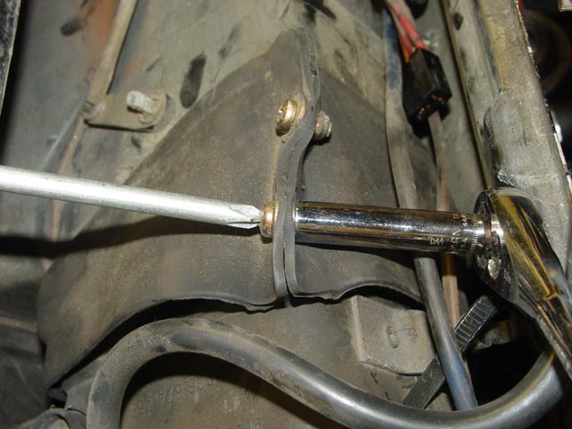
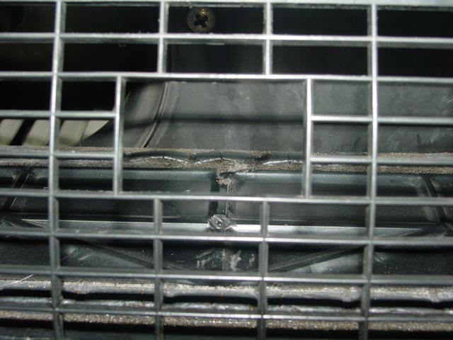
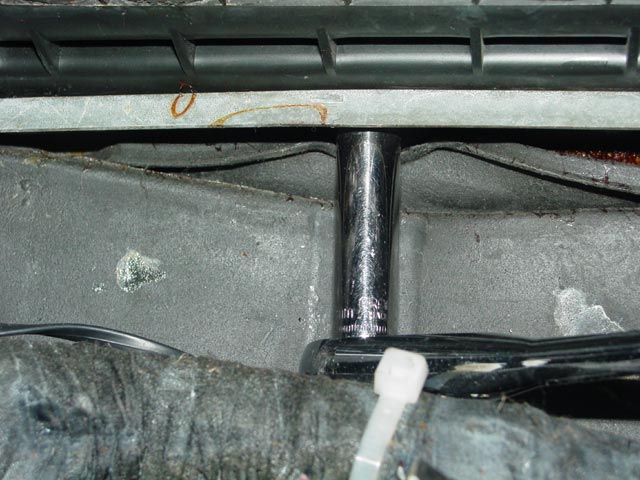
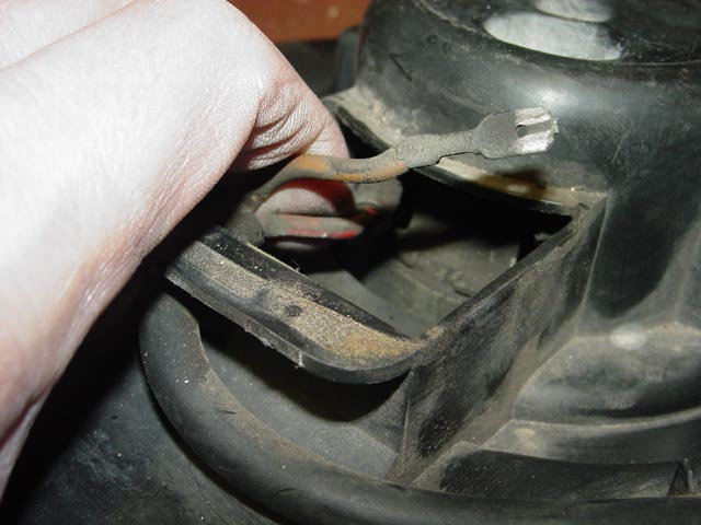
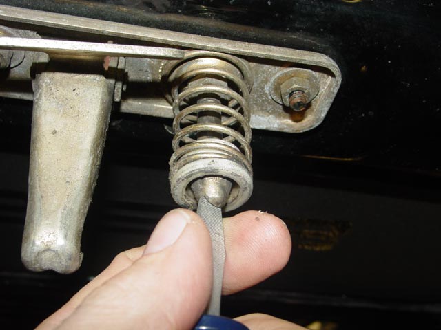
Finally, I found the third screw holding the blower in. If you hold the recirculation flap open, you can see the screw with a mirror or you can see it if you can crawl under there and look up and a bit rearward. It's at the top of the pic. The white plastic fan impeller is also visible in this pic, at the left..
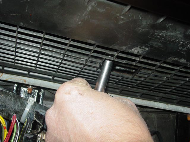
It's a bit tricky finding the screw with the screwdriver, but once you do it comes right out. Note that on later model cars the screw will be even farther to the rear.
The diaphragm on top of the housing is the main closing flap that closes off the duct when the HVAC control is set to "OFF". This flap needs to be closed to remove the blower, because when open it extends out of the duct and interferes with blower removal. I used a Mityvac to hold it closed.
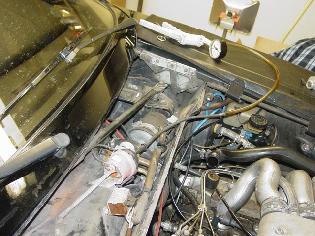
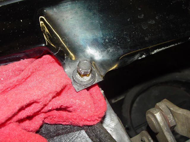
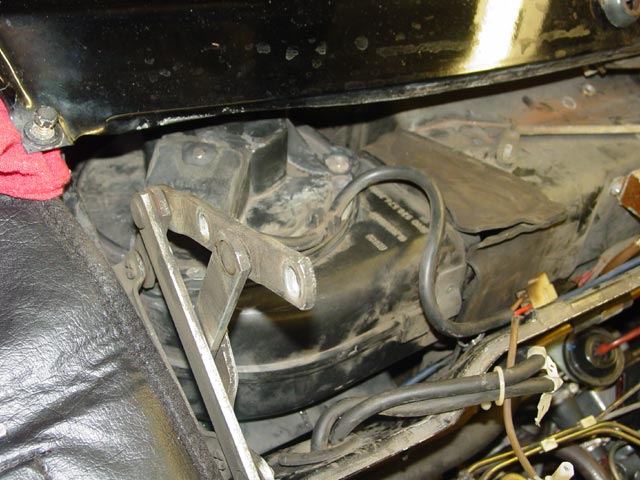
The one bolt that holds the valence down near the rear inner edge of the fender has to be loosened to allow the valence to flex upward. I had put this rag under the edge of the valence to prevent scratching while I moved it around. It ended up doing a great job of protecting the paint.
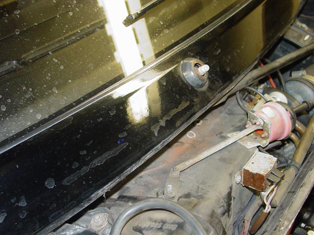
The blower was almost ready to come out, but the valence wouldn't quite flex far enough. The passenger side wiper needed to come off. I flipped up the cap and removed the nut holding it on. I swung the wiper away from the windshield into the "up" position and the wiper arm lifted off of the shaft easily.
With the wiper off the valence easily flexed far enough to get the blower motor out.
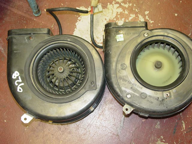
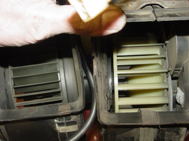
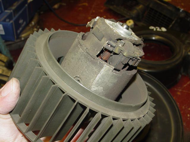
Here is my old blower(right) and the later model blower(left). Note the different location for the third mounting screw, about the 5:30 position on the old blower and about the 4:00 position on the later version. While I had the recirc box out I marked the location for this hole on the later blower. Also the second screw hole is in a different location, but since that is only a through hole that will be easier to address. Unfortunately, I cannot put the lower half of the old housing on the upper half of the later housing, because they are not spilt in the same location. The old fan has slightly wider blades measured axially, but they are shorter radially and there are fewer of them. I connected both fans directly to 12v and the later model fan seemed to blow quite a bit harder.
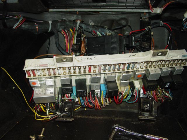
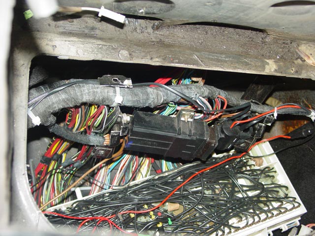
Moving on, I wanted to re-seal the recirc box, so I had to get it out. This required unmounting the CE panel from its brackets and removing the brackets. Each bracket has one bolt that goes into the floor and one nut at the top threaded onto the same studs that mount the recirc box. Once all of the fasteners were removed, I pulled at the bottoms of the brackets and like magic they pulled out and down while the CE panel moved and tilted rearward.
Here is a closer look at where the brackets attach to the studs.
I removed the nuts holding the angle bracket in place, and the two nuts on the studs that also supported the package tray.
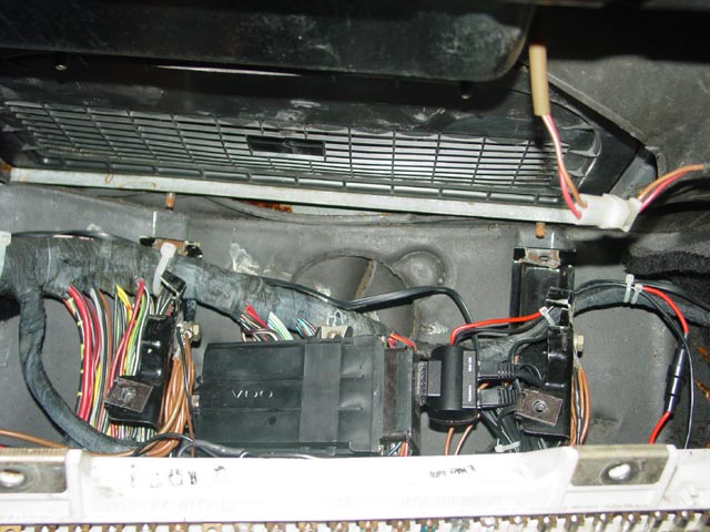
With a little initial prying to get things started, the recirc box popped loose and I was able to maneuver it out. It was a bit of a pain to get it out, I had to find just the right angle. The driver side wants to come out last and go in first because of the lip around where the blower mounts.
BTW the recirc box has a diaphragm and vac line on it for the recirc flap. There was a coupler in the vac line in the cowl area that I disconnected so the vac line was free. If yours doesn't have such a coupler, consider cutting the line where it's easy to reach, and put a coupler in when you put it back together. I meant to replace the diaphragm in this actuator, but it was glued together unlike the later versions which can be rebuilt... since it was still working fine I decided to leave it.
With everything apart it was time to see if I could put the guts of the later blower into the early housing. Either way, I wanted to lube the bearings. It's pretty straightforward disassembling the late blower. First I popped all of the metal clips off of the outside so I could split the shell.
Then I removed the clip holding the cover over the electrical connections.
The cover then lifted off, exposing the wires. The bolt at the bottom right of the pic holds the motor in the housing, so I removed it.
The wires attach directly to the motor, and come off with a firm pull. They can't be reversed, so I didn't bother to mark them.
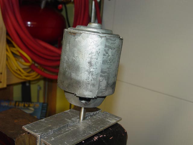
With the blower and impeller out of the housing I began to look it over. It didn't look too bad at first, just a bit dusty.
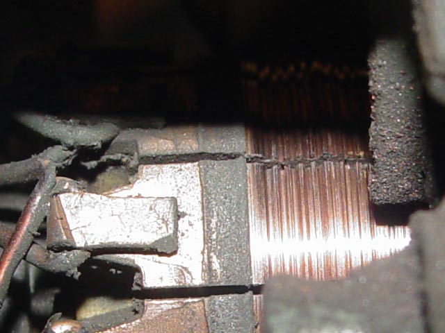
On closer inspection though, it turned out the brushes were worn down to nubs and the commutator looked awful, heavily grooved. That killed the idea of putting this blower in, at least for now. I decided to see if I could find someone who could repair it, but for the short term I needed to make the best of the old blower.
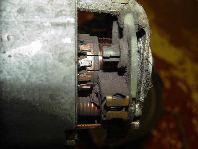
Here's a closer look at the commutator. It was really wasted.
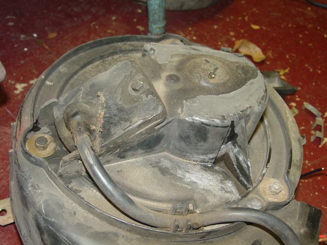
The original blower is an entirely different construction. There is a 3-bolt flange on either side of the housing, the lower flange(above) serving no obvious purpose, and the upper flange holding the motor. There is a tar-like substance sealing the motor mounting bolts and electrical cover.
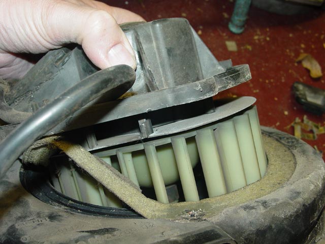
Once I removed the three mounting bolts, the motor and impeller lifted right out.
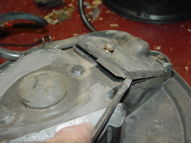
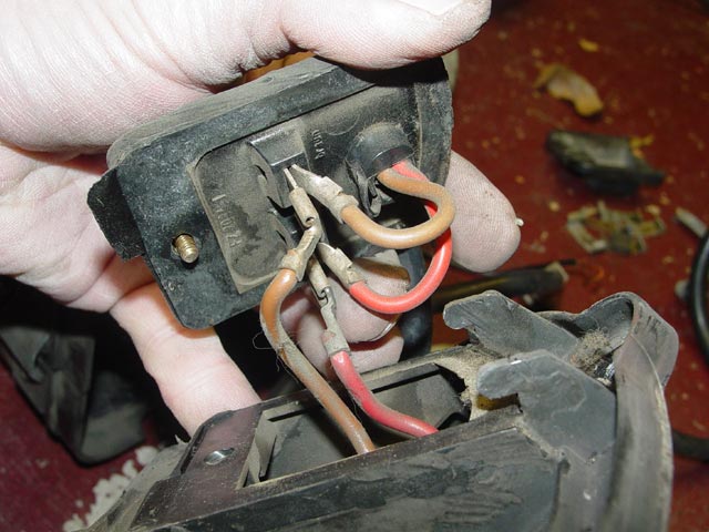
After removing the one bolt on the electrical cover, it lifted right off. I had to break the sealant, but it's not very strong.
There is a simple connection point on the back side of the cover. I disconnected the motor leads.
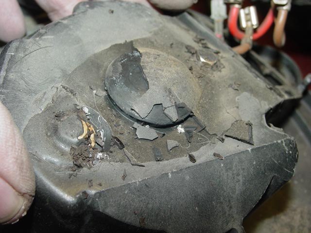
The sealant on the top hid an inspection plug. It broke apart pretty easily, and I removed the bolts. The motor slid out relatively easily, I just had to push and poke the motor leads a bit because of their convoluted routing inside the housing.
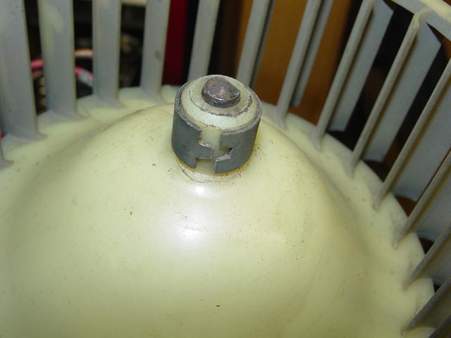
There is a spring clamp securing the impeller to the motor shaft. In order to lube the bushings, this would have to come off because I couldn't reach the front bushing otherwise.
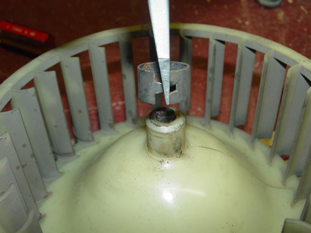
After noting how far the shaft protruded, I lifted off the clamp. I used a pin drift with the impeller supported by the open vise jaws to gently work the motor free of the impeller.
With the motor free, I stuck it in the vise and put a fair amount of teflon lube on the top of each bushing. I was able to reach the lower bushing through the access hole shown.
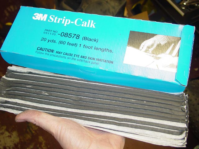
While the bushings in the motor soaked, I went to work on the recirc box. While I didn't have any water leaks in this area, I wanted to get in there and guarantee that I would not have leaks in the future. I picked up a box of 3M strip calk at the local independent auto parts store.
In preparation, I cleaned out the leaves and gunk in the cowl area. There was a good sized accumulation of leaves that had not broken down enough to clog the drain, probably a double handful. I wiped up most of the decomposed leaf sludge as well.
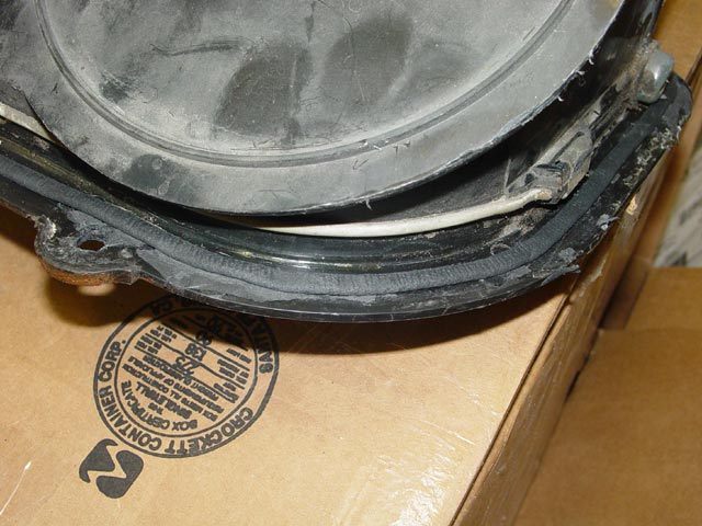
The original gasket on the recirc box was still in surprisingly good shape. Rather than try to replace it entirely with the calk I decided to just enhance it a bit.
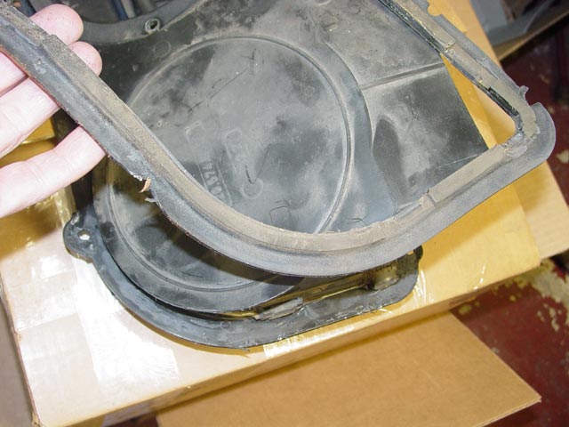
First I put a bead of calk around the edge of the recirc box. I didn't push it all the way into the corner, partly because the gasket is a tight fit in places, for example under the clip that holds top & bottom halves of the box together and under the flap pivot, both at right of the pic. Also, when the box is pulled up tight against the body the gasket is not compressed in that area.
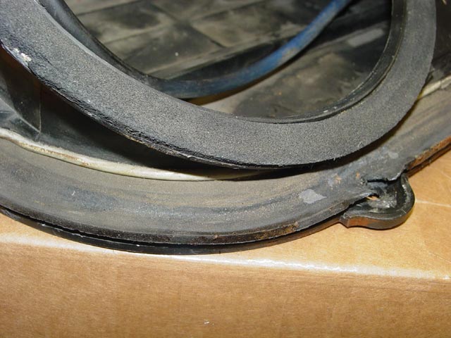
I worked the gasket into position, taking care to not push the first bead of calk out of place.
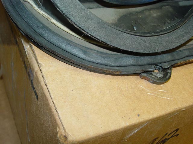
I then put a second bead of calk around the gasket where it contacts the opening in the body.
I installed the recirc box, being very careful not to disturb the calk in the process. I had straightened the angle bracket prior to assembly, but it flexed as I tightened the studs. I placed a towel over the wiring and CE panel, and poured a pitcher of water around the recirc box from above to check for leaks. There was one drip that came from water spilled through the opening where the blower mounts to the recirc box, but otherwise it didn't leak. Success!
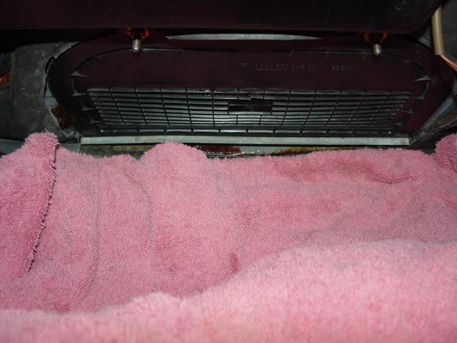
I had stuffed a towel in the opening to prevent water from splashing in to the recirc box, but a little got in anyway.

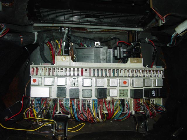
The next step was to re-mount the CE panel brackets. First I engaged them with the studs at the top rear, then pushed them into place and bolted them to the floor. In the processes I had to make sure that I didn't pinch wires between the brackets and the firewall.
After that I re-mounted the CE panel to the brackets.
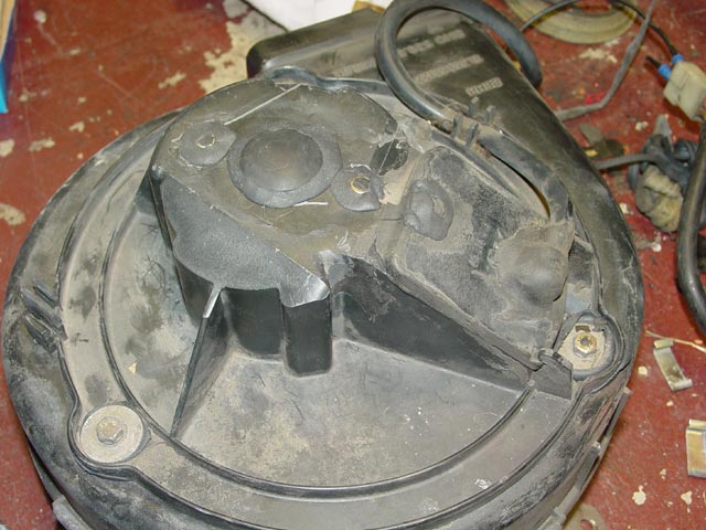
Since I was unsure how long it would take to get the replacement blower sorted out, I decided to do a good job of re-sealing the old blower against water intrusion. First, I cleaned off the original foam gasket.
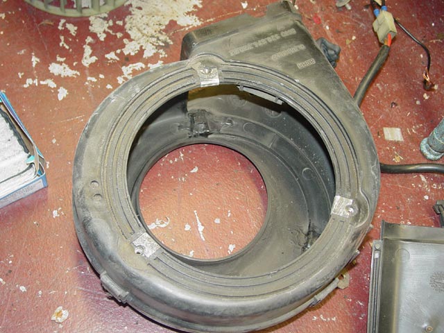
I then put a bead of calk around the outside of where the gasket had been. Initially I though of extending the bead 360� around the mounting holes, but upon reflection I decided that wouldn't be enough. There were too many paths for water to take around and through the speed nuts.
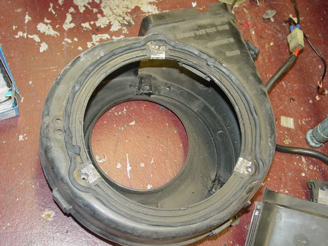
Instead, I put a ring of calk around each of the mounting bolts to prevent water from entering in the first place. Heh... calk ring. Heh heh.
I sealed the motor mount bolts and the top inspection plug from the outside, my intent being to prevent water from pooling in these areas. The electrical cover was sealed with a very thin bead of calk on the mating surfaces.
I dropped the blower back in and started the two top screws, leaving them loose. I then went back inside and installed the third screw inside the recirc box, tightening it before going back to the top and tightening the other two screws. I reattached the boot on the duct, then reinstalled the CE panel wood cover lower and upper sections, replaced the package tray, and put the floor mats back in.
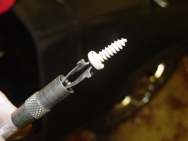
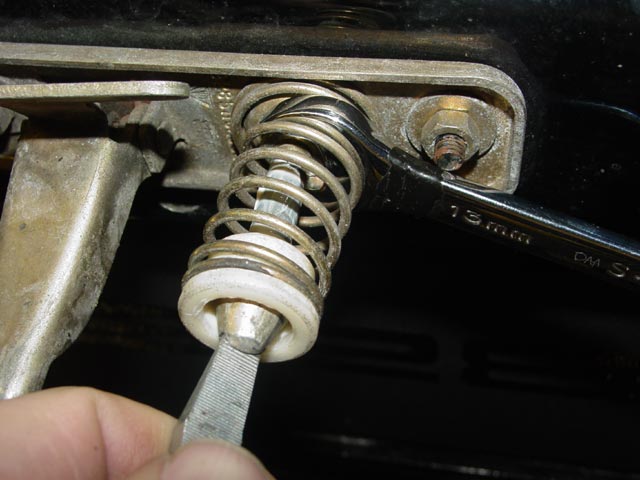
Side note - a screw starter, such as the one pictured below, is a real lifesaver in this situation. There are a number of different tools that will help you accomplish this task, just have one on hand before you start. If you don't have one, you could use the calk to stick the screw to the screwdriver (or socket if you have hex heads).
I have a replacement cowl cover, clips and seal, but I decided to re-use the old parts for now. I will install the new parts when I get back in here to install the later blower.
Once all of the adhesive was off I cleaned the underside throughly with a strong mix of Dawn dish detergent and water, which was also brushed around under the edges with a clean paint brush. I rinsed it thoroughly with water before setting the hood on edge to dry. Here is the hood after all cleaning and drying overnight. The yellow material was brushed onto the underside of the hood and appears to be a thick paint. The dark patch, which sits above the oil filler, was some sort of material that would not loosen with any of the solvents that I had handy.
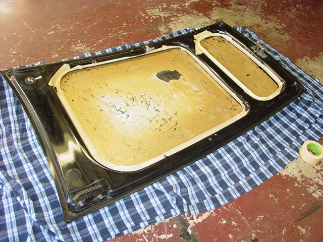
The next step was to mask the areas that I didn't want to get spray adhesive on. I started with 2" masking tape, tucked under the edges of the hood frame.
I then taped newspaper to the masking tape that I had already laid down. I had trouble working around the underhood light, so I unscrewed it and laid it aside. I filled in the area on the cross rib where the seal on top of the radiator makes contact with 2" masking tape.
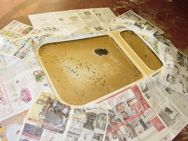
I laid out some extra newspaper for spraying glue on the hood pad pieces themselves. I didn't want to glue my feet to the floor!

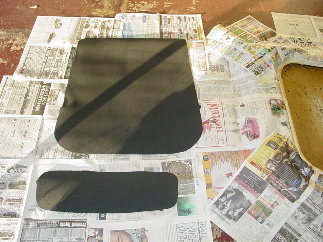
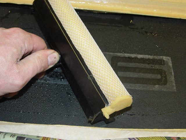
I used the 3M #80 hi-temp neoprene adhesive recommended by the supplier of the hood pad, Rob Budd who runs The 928 Leather Shop. I sprayed a thick coat of adhesive on both the hood and the pad. It's very important to spray the glue on the textured side of the pad, since the decals can only be applied to the smooth side of the pad. The pad is made from a 1/4" thick closed cell nitrile foam, which should be impervious to any chemicals it should come into contact with and will not hold water or other liquids like the OE open-cell foam pad would.
I started with the nose piece, since I could handle that myself easily. I let the adhesive dry to a tacky state before laying the pad in place. I then enlisted the revlimiter for the main pad, again spraying a thick coat of adhesive on both the hood and the pad and letting it tack up before we carefully laid it in position. I used up most of a can of the #80 adhesive on the project. Some air bubbles seemed to be inevitable. Most of them were easy enough to work out toward the edges, but as the adhesive firmed up some of the air bubbles could not be moved out. To get rid of these I poked small holes in the pad and squeezed the air out.
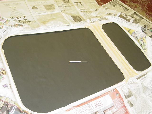
With all of the air bubbles removed, this was shaping up to be a very professional-looking job.
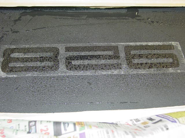
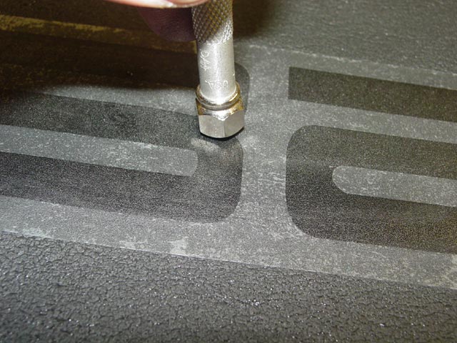
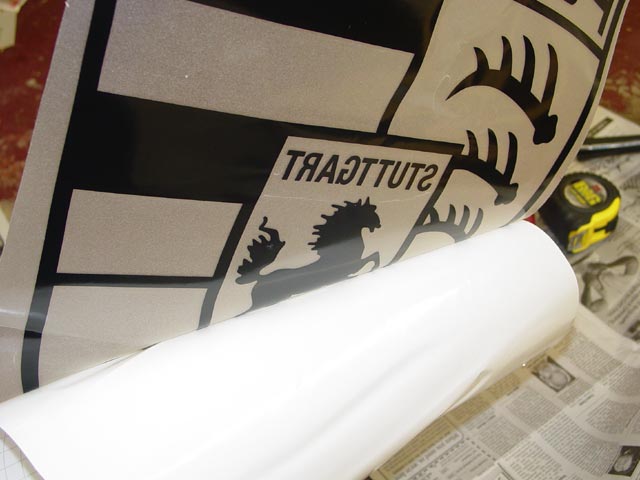
The next step was to install the decals. I wanted a more subtle look than the red or silver decals that are available in Rob's website, so I contacted him and requested black decals. The decal for the nose piece is available in "928" or "Porsche" variations. Since I planned to use the Porsche shield for the main decal, the "Porsche" nose piece decal seemed redundant so I went with the "928" decal. Per his instructions, I wet the pad and the decal so that I could reposition the decal as needed until I was satisfied with the position. You can just see the mark that I made at the top center of the "2" to help center the decal.
Once I had the decal where I wanted it, I squeegeed out the water to press the decal in place.
I used a rounded tool to thoroughly press the decal in place.
Finally, I peeled off the backing parallel with the surface to avoid lifting the decal.
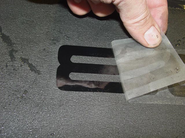
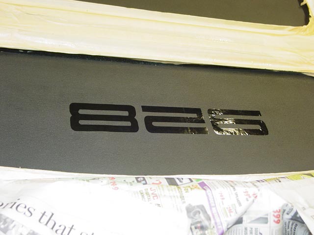
It came out nice, which was very encouraging. I laid some waxed paper over it and smoothed it down.
I took the same approach with the larger shield decal, first peeling off the paper.
I then thoroughly wet the decal and the pad.
I then carefully positioned the decal. I had marked the centerline of the decal on the backing as with the smaller decal, but this one still required a bit more fiddling to get it right.
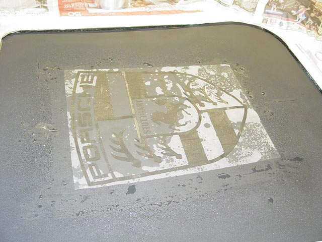
Once I was satisfied with the position, I squeegeed out the excess water.
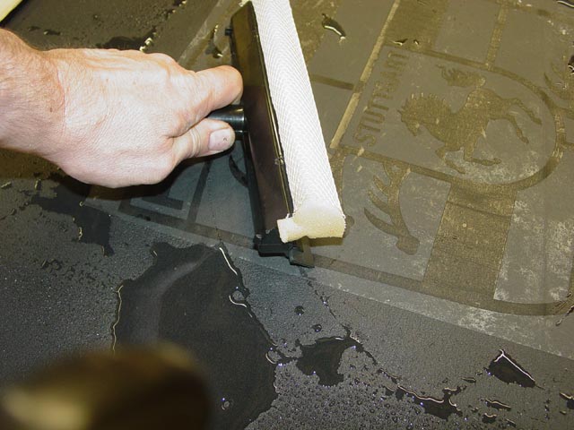
I wiped up the excess water, then squeegeed again and wiped again.
I started peeling off the backing a bit too soon, which caused the decal to lift. I laid the backing back down, squeegeed it again, and waited a bit longer for it to dry.
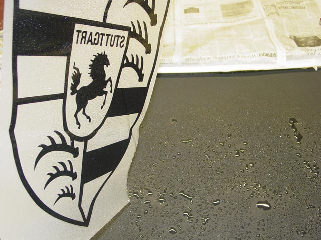
After letting it dry a bit longer, I succeeded in pulling off the backing. I still had some issues around the finer features like the horse's feet and the whatever-they-are at the top left and bottom right of the crest, but I just went slowly and carefully until I had the backing removed. Again I laid down some waxed paper and pressed the decal into place.
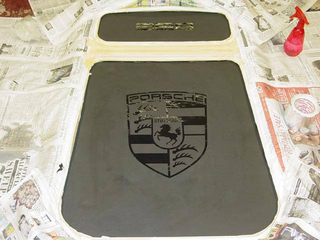
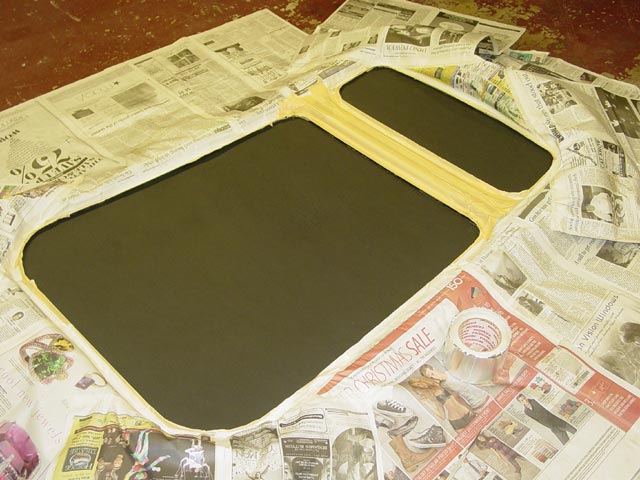
With the masking tape and newspaper removed, this was really starting to look good.
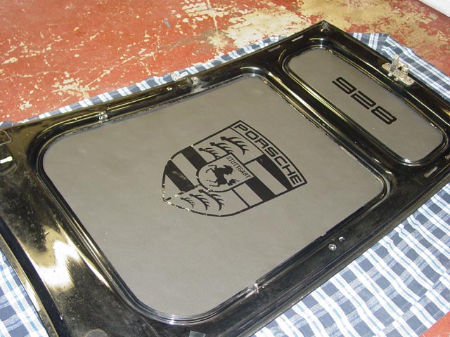
Before installing the hood, I thoroughly lubed the 5 pivot points on each hood hinge with teflon lube. With a little help, I installed the hood loosely and put new hood shocks on since the old ones had just about given up. It looks so good now compared with the ratty old liner that I'll have my hood open more often at events. I'll have to do some engine cleaning too, because now the engine bay looks a bit rough compared to the hood.
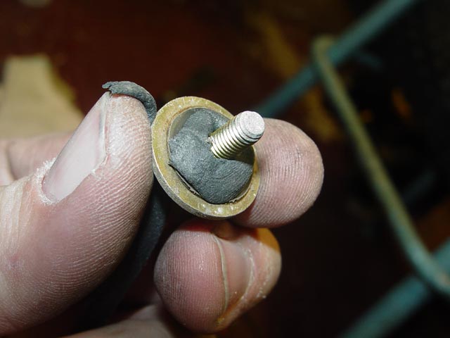
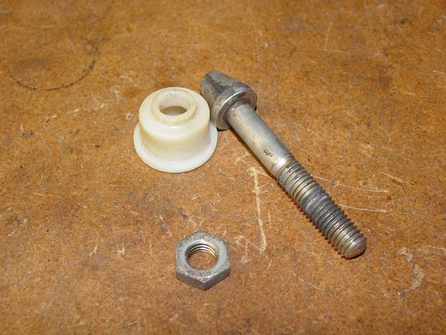
The latch pin on the hood was looking a bit grungy so I decided to clean it up and re-lube it. I broke the locknut free and counted the number of turns it took to remove it so I could get it back in approximately the right position.
I cleaned the parts of the sticky old grease with mineral spirits.
I lubed up the sliding bushing with Lubriplate.
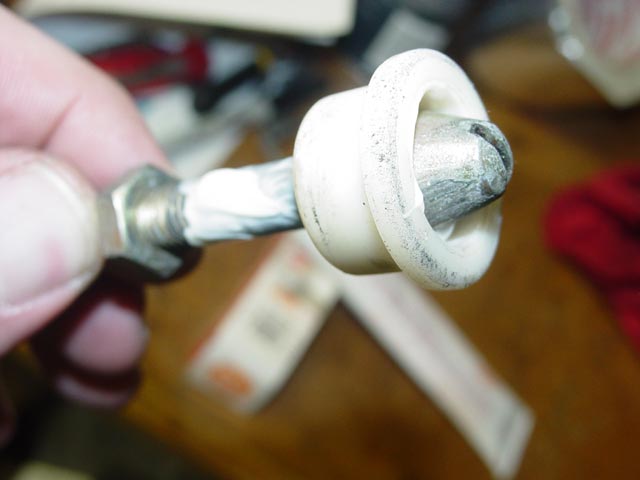
I screwed the pin back into its original position, again counting the turns, and cinched the locknut back down. The result is that the hood pops up more easily when released, and latches easier now that the plastic bushing slides freely.
I also adjusted the hood to fit more evenly in the opening, and brought the height down at one of the rear corners. It now fits better than ever. The HVAC blower seems to blow marginally better, but I still want to fit the later blower when I have a chance. When the car has been driven and the engine heat-soaks afterward, the hood is not even warm to the touch, so the hoodpad is doing its job wonderfully.
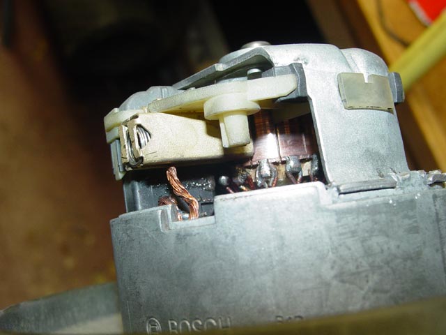
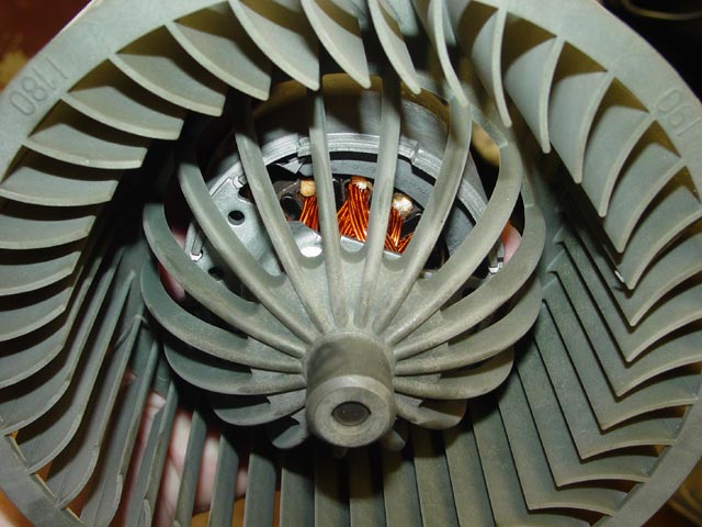
I'll be updating this page as I move forward on upgrading my HVAC blower. For now, here are some pics of the rebuilt unit. Below, looking into the intake side.
New Commutator
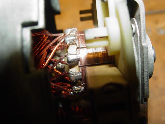
New brushes. Note the fully compressed brush spring, and the amount of available travel indicated by the copper braid.