
The Larcan amplifiers come in three frequency ranges with three power ratings in each.
The low band amplifier modules are designed for 54-72MHz (lo/lo) and 72-88MHz (lo/hi) operating ranges. The high band amplifier was designed for 174-230MHz.
The driver amplifier uses a pair of MRF151G. It is good for up to about 600 watts output on the low band modules. Due to the output coupler rating, power output for high band is only 400 watts.
The 1kW modules use four MRF151G and the 1.5kW modules use six MRF151G.
Gain of the lo/lo module is better than 20dB at 54MHz. This is the one preferred for 6-meters. Typically less than 10 watts is required for full output with a 1kW module or 15W drive for the 1.5kW module. Performance should be even better at 70MHz as the amplifiers have higher gain and operate within the original design frequency range.
Gain of the high band module is about 16dB at 222MHz. About 25 watts drive needed for 1kW or 40 watts for 1.5kW, depending upon module power rating.
An attenuator should be installed on the main board if desired. This will eliminate overdrive problems and potential damage to the FETs. For example, if your rig operates full power at 100W on 6-meters, and the amp needs only 10W, a 10dB attenuator will allow full transmitter power to the module. There is no concern about spikes or accidentally leaving drive power too high. It is cheap insurance against transistor replacement. I can install this during conversion as an added extra, but will need to know well in advance to order suitable parts.
There lo/hi modules can be modified for 6-meter use or used as is for 4-meter / 70MHz. They can also be converted to 2-meters. Conversion information is available below.
I think if you compare these amplifiers to tube amplifiers it will prove an attractive approach. The 1kW and 1.5kW amplifiers are about 17x24x3 inches. Drivers are about 10.5x15x2 inches. The amplifiers are wide band and require no tuning.
They will work with an inexpensive 48-50VDC power supply. A 60A supply can be purchased on eBay for about $40. (Search for 48V 3000W power supply) Here is a spec sheet with pinout for the power supply .
I picked this up somewhere. No idea on the source.
Subject: HP 226519-001 connections
Looking at the pin field, the pins count from left to right 1 through 5.
From the 'BOTTOM" row to the top, they are designated as rows A through D.
As an on/off control, shunt pins A3 and B3.
To enable the supply, shunt pins D2 to D3.
Always use a "2 pole" AC on/off switch in the 240 VAC feed from a circuit protected with a breaker or a fuse.
Transmit/receive switching and cooling fans will finish off assembly. There are no high voltage components needed.
The first pictures are 1kW "low-split" modules and do not require modification for 6-meters.
They will also cover the 70MHz / 4-meter band with no changes.
Presently no lo split available, but working on leads.
The high band 1kW and 1.5kW modules are the same physical size. The heat sink, rear panel connectors, and circuit board are identical. The only difference is in the strip line circuitry. 600W/1kW 50MHz module gain is about 20dB/100x. The 400W/1kW/1.5kW 222MHz module gain is about 16dB/40x.
Click thumbnails to enlarge.


2-meter conversion
The low band modules must be converted for use at 2-meters. With some modification they will easily produce 1kW on 2 meters.
My changes are based upon this writeup by Brian Justin, WA1ZMS,
with a few minor changes
as suggested by James WA3LBI and others that I plan to make. If you have other improvements please share with the class!
I can offer modification service for others but shipping to and from would be an added expense.
I've tested several of these amplifiers at 1kW output power, 100% duty cycle for a full hour. They were rock steady and good for more. I can't imagine any amateur use being more demanding. Try that with any other amplifiers presently on the market!
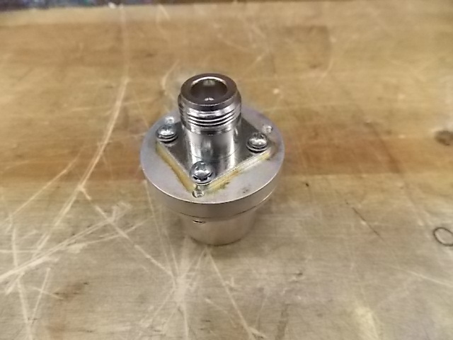
RF connectors
From Paul W2HRO
The L4TDF-PS is manufactured by Andrew to terminate Andrew LDF4-50A Heliax with a DIN 7/16 Female connector. I found that this L4TDF-PS works nicely as a
Larcan output connector adapter.
The L4TDF-PS will slide nicely into the Larcan original factory output connector.
A simple hose clamp can be used to secure the L4TDF-PS
while inside the Larcan output quick connector. This approach is simple, mechanically strong and I have seen no RF problems.
I checked the Andrew 1/2" Heliax to N-Male and this works too. I don't have an Andrew 1/2" Heliax N-Female to test but it should work as well.
The Larcan factory slide in "quick" connector appears to have dimensions compatible with the Andrew 1/2" Heliax connector so the any 1/2" Heliax connector should work.
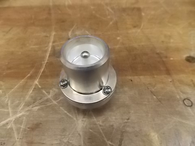
I also found that the
Amphenol 4 hole flange N-type female connector
will mount perfectly on the factory original input connector posts. No drilling was required. All that was needed was a small soldering project to the connector center pin.
There is a long message thread about the Larcan amplifiers at World Wide DX in the amplifier forum.
A more detailed write up for 6-meter operation is available at
http://www.gemoto.com/LarcanPA.htm
(Note: This is NOT my web page and is supplied for information purposes only)
The techniques used are very similar to that required for the high band 222MHz module.
Harris 1kW amplifier for 6-meters were available for a short time. The experience was less than stellar and they will no longer be sold. The remaining modules will be offered as parts only. It may be the only way to get a replacement FET as they have become obsolete and unobtainium. This page has information for the Harris amplifier. It has ideas for coaxial switch, RF filters, cooling, power supply, etc. that are also applicable for use with the Larcan. (Again, not my web page, etc...)
VK5PJ has information on improving performance of lo/lo modules at 50MHz.
Simplified 50MHz improvements. I recycled capacitors from 2M conversions.
Input splitter:
C1, C2 Add 15pF. C3, C4, C5, C6 Add 47pF.
FET Amp output (x4):
C16 Add 24pF. C14, C15 Add 51pF.
Output combiner:
C1, C8 Add 15pF. C2, C3, C4, C5 Add 47pF.
KH6HAK has suggestions for mounting a metal shield cover over the PA circuit board and building a slide on output connector adapter.
 The amplifier modules were removed from commercial television broadcast equipment and are rated for 24/7 operation.
They use commonly available MRF151G transistors. There are no known problems with any of the modules. All in very good physical condition and are bench tested prior to sale.
Be VERY careful with input drive level. One sure way to wreck the transistors is to apply too much RF. All that is needed on 6-meters is about 10W drive for full power output. If your rig can produce 100W it is highly recommended to install a 10dB attenuator at the amplifier input as shown in the photo. That way you can be certain never to overdrive the input. It is very inexpensive insurance against damaged FETs. The photo is from an owner who installed a 6dB pad into a 1kW lo/lo module he converted to 2-meters.
Here are schematic diagrams, circuit descriptions, alignment information, etc.
1.5kW high band schematics
1.5kW high band alignment and circuit descriptions
1.5kW low band schematics
1.5kW low band alignment and circuit descriptions
1kW LoLo frequency response curves
1kW LoHi frequency response curves
1kW 222MHz frequency response curves
222MHz 400W amp schematics
222MHz 60W amp schematics
PA testing
FET Testing
MRF151G specs
Terry Price at Directive Systems has a very informative writeup for his 1.5kW 222MHz amplifier. He has also assisted with similar mods for others.
 Packaged weight is about 23kg / 51 pounds.
The crate is built with 3/8 inch plywood and 2x4 sides.
It has proven very reliable for shipping.
 This is a high band VHF module that would work on 222MHz with no changes needed. The modules were built for operation from 174MHz - 230MHz. As far as Larcan amps go, this one is essentially plug and play with about 16dB gain or 40x amplification at 222MHz. Notice it uses six transistors instead of four.
 These are Larcan drivers. Parts that are not needed - extra heat sink with power divider, side rails, and front panel have been removed to reduce size and shipping costs but remain fully complete RF amplifiers. The 222MHz version is shown.
Here is how it looks before removing extra parts.
The 50MHz version is very similar with different strip line sections. RF input is on the left, RF output on the right, and +48VDC connects to the bus down the middle.
These are Larcan drivers. Parts that are not needed - extra heat sink with power divider, side rails, and front panel have been removed to reduce size and shipping costs but remain fully complete RF amplifiers. The 222MHz version is shown.
Here is how it looks before removing extra parts.
The 50MHz version is very similar with different strip line sections. RF input is on the left, RF output on the right, and +48VDC connects to the bus down the middle.
Based on MMRA web page, the 6M modules should be capable of 600 watts output. The output coupler on the 222MHz amp is rated at 400 watts CW. I haven't used either of these so can not guarantee MMRA numbers.
The driver modules will be shipped in custom built crates. 2x3 sides with 3/8 plywood top and bottom.
6-Meter version shown.
Picture 1,
Picture 2.
There are also smaller driver amps that use a pair of MRF148 transistors, good for about 50W output.
Look at IPA1 and IPA2 at
MMRA web page.
Here are
schematic diagrams for high band and low band IPA1.
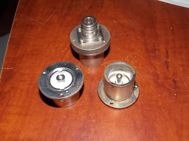
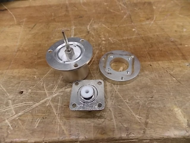 Slide on RF output adapters can be fabricated from the original chassis mount connectors. I have a very limited supply of these. The 1/4 inch spacer and Type-N (or SO239)chassis connector would have to be obtained elsewhere.
 I can supply a full set of Larcan adapters to anyone interested.
 The original 8-module wide frame can be cut down to accomodate 6 PA modules. It will then fit inside a
standard 19 inch equipment rack.
The slots can be populated with any model PA (other than the IPA). Outputs can be paralleled to create even higher power. My plan is to have two modules for each band 50MHz, 144MHz, and 222MHz. Add power supply, fans, etc.
The original 8-module wide frame can be cut down to accomodate 6 PA modules. It will then fit inside a
standard 19 inch equipment rack.
The slots can be populated with any model PA (other than the IPA). Outputs can be paralleled to create even higher power. My plan is to have two modules for each band 50MHz, 144MHz, and 222MHz. Add power supply, fans, etc.
I've shipped modules to USA, Canada, Caribbean, and Europe. A list of references is available. Check my feedback on eBay, username Warren914
Grounding ideas and techniques and other RF and broadcast items I've written.
Please email me - vo1ks@eastlink.ca with any questions.
73 de VO1KS
For purposes of disclosure and so on, perhaps some background is in order. I work in broadcasting and have installed, maintained, and repaired Larcan and other TV and FM transmitters for many years. The amplifier modules and other parts pictured were obtained legitimately through other sources. The use of this equipment for amateur radio purposes should not in any way be interpreted as an endorsement by either my employer or Larcan, nor in any other way related to my regular work duties.