Generator neutral and ground rewiring
Return to Home Generator Installation
Updated 16 November 2012
If you have other suggestions, comments, questions, or corrections please contact me. An email link is at the bottom of the page.
If your transfer panel does not switch neutral, the generator should have its neutral conductor floating, not bonded to the chassis. Having a second bonding point will not prevent the system from working. Your lights will come on, but your safety will be jeopardized. If you are going through the expense and effort to purchase and install a backup power system do it properly.
Take a look at return current flow along the neutral and ground conductors. If you have only three conductors, such as with the neutral bond in the main panel and in the generator (or with just a 3-conductor cord), there will be no separate and independant ground conductor bonding the generator frame back to your house ground. There is a potential of the chassis becoming live as there is current flow along the ground conductor.
Remove the neutral bond and now all return current flowing from the live conductors will flow along the neutral conductor only. It will not flow along the ground conductor. This will ensure the chassis remains at the proper potential.
To meet electrical code requirements for stand alone operation, neutral and ground should be bonded together. This can be accomplished quite simply with a standard 120V 15A plug with ground and neutral jumpered and plugged into an outlet.
Picture is here. Many of the Chinese built generators with a built in 120/240V selector do some very odd things with the switch. I do not recommend using the neutral/ground jumper plug with those generators.
My personal opinion (and that of others who I have discussed the issue with) is that floating neutral is safer for stand alone operation. Consider having the generator chassis connected to a suitable ground rod. You are a few feet away, standing in a puddle of water with bare feet. Holding one of the live wires in your hand, there is no return path from the neutral conductor or the other live line through the chassis. With no path for current to flow you will not experience an electric shock. If the output uses a GFCI outlet it will not trip. Let's install the neutral / ground bond again and the return current path exists through your feet to the grounded chassis, through the bond jumper to the neutral conductor. You can be assured of a nasty jolt. If there is a GFCI outlet in place it should open. Which situation is safer? In my opinion floating neutral is better, but the electrical code says it should be bonded. It may seem I'm going against my own advice and I won't tell people to go against code requirements, so follow the rules.
Rewiring will likely void any remaining warranty as well as UL/CSA certification of the generator. In my case warranty is not important, and I feel safety has not been jeopardized in any way. In fact the system is safer now than it was originally.
Proceed at your own discretion and risk.
Determining whether your generator has a floating or bonded neutral
 To determine if your generator uses a floating or bonded neutral perform this simple test. With the engine off, use an ohm meter between the chassis and neutral conductors in the outlet. If it indicates open circuit, the neutral is floating. A short circuit will indicate neutral bonded to ground. I don't recommend doing this to household circuits due to the possibility of exposed AC and damage to the meter.
Don't trust the generator label. I've seen many in which it is incorrect. Confirm for yourself either way.
It is normal for to read very low resistance between the neutral and live terminals on the outlets. You are measuring the DC resistance of the output coils.
Plug in an electrical tester as shown and start the engine. If it indicates open neutral, live/neutral reversed, or live/ground reversed do not use the generator and have someone qualified check the wiring and make the necessary repairs. Use the tester throughout your house to ensure it is wired correctly. This sort of tester is often inaccurate for determining whether the neutral is bonded or not. Even with a floating neutral, the second light will often be on. I suspect this is due to very low leakage currents and a high impedance bulb in the tester.
DeVilbiss GT5000, GT5250
My former generator, a
DeVilbiss GT5000
was supplied with a duplex outlet for 240VAC. The three wire connection with bonded neutral and ground was not suitable for my transfer panel. It was rewired to use a
four conductor twistlock outlet,
type NEMA L14-30 30A 125/250VAC. The outlet shown in the picture was later replaced with a L14-20 20A outlet. As a backup power supply for my home, I required the neutral line to be isolated from ground.
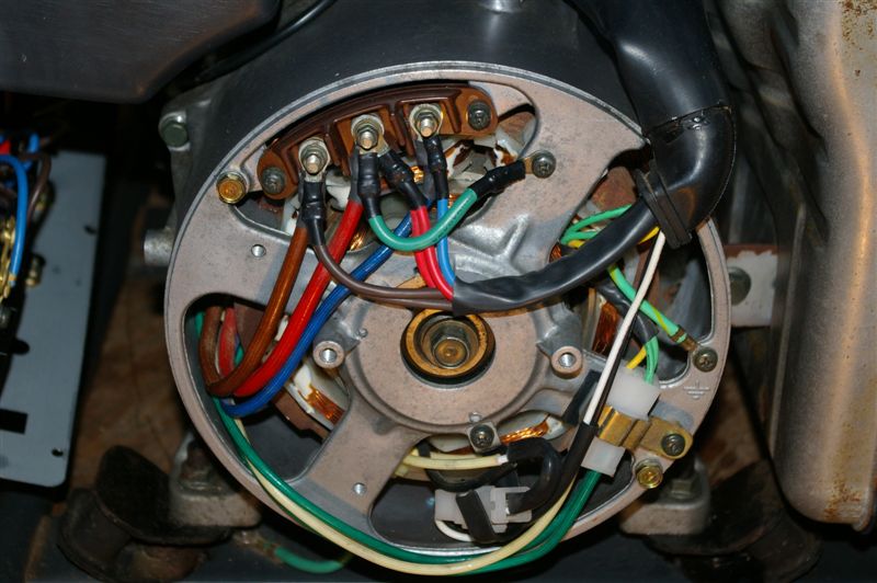
There are two output coils in the generator and four wires coming to the output panel.
They are paired as red/green and orange/black. Each coil generates 120VAC.
Orange and green are used as neutral and connect together and attach to the neutral connections on both outlets.
Red and black are used as live lines and both connect directly to the circuit breakers.
From the circuit breaker outputs, connect red to one of the 120VAC outlets and black to the other. Red and black also connect to the live lines on the twistlock plug.
Remove the jumper from ground to neutral, likely on the 120VAC duplex outlet and connect ground connections on both outlets to the chassis.
Note the green wire from the generator coil is not the same as the green wire used for grounding. Be careful not to get the two mixed up!
Make a new label for the electrical panel stating FLOATING NEUTRAL.
Each output coil creates 120VAC up to 2500 watts maximum, and when operated together supply up to 5000 watts. If required, both output coils can be permanently wired in parallel to provide full 5kW output at 120VAC. 240VAC will not be available in this configuration. Alternately, a switch can be installed to select either normal 120/240VAC operation or full 5kW output at 120VAC only.
I've hand drawn a
diagram for both methods.
Top of drawing shows twistlock 120/240VAC plug.
Bottom diagram has 4PDT switch to select either 120VAC only or 120/240VAC operation.
On the GT5250, there is a green jumper wire on the duplex wire going from the neutral connection to ground. Remove it for floating neutral.
Here are
wiring diagrams for the full DeVillbiss generator lineup, including many Porter Cable models.
DeVilbiss equipment manuals can be found at DeVilbiss manuals/breakdown web site.
Generac Wheelhouse 5500
Using a 3/8 inch socket, remove four nuts holding the electrical panel in place. Pull it out of the frame. Remove the four screws holding the cover in place. On one of the 15A duplex outlets there is a green wire jumper between neutral and ground. It is wire (0) on the electrical diagram in the manual. Remove the jumper and put things back together. Make a new label for the electrical panel stating FLOATING NEUTRAL. Make notes in the owner's manual for the changes made.
Generac 4000EXL 5500XL 7550EXL
Refer to the wiring diagram and electrical schematic in the owner's manual as a guide to the work.
7550EXL wiring diagram. The 4000EXL and 5500XL are the same with the exception of the 12Vdc starter and associated battery charger and 15A breakers feeding the 120VAC outlets.
Remove four philips screws to gain access to wiring in the generator electrical panel.
On the 120VAC duplex outlet there is a jumper between ground and neutral. It must be removed. This is the bonding wire. Next, look for a green wire coming from the control board inside the electrical panel. It connects to the 120V 30A L5-30 twistlock outlet. Relocate it from the ground to the neutral connection. This will ensure the auto idle circuit operates properly.
Here are before and
after pictures for the 7550EXL with the appropriate wires labelled.
Thanks Mike P for confirming the wiring and supplying the pictures.
Here is a picture inside the 4000EXL electrical panel.
Use an ohm meter and measure DC resistance between the neutral and ground output terminals. It should read as an open circuit, no longer zero ohms. Confirm the ground terminal and chassis remain at zero ohms. You should measure essentially a short circuit between each of the live wires on the 120V duplex outlet, and between each live line and neutral on the same connector. Put the electrical panel back together and start the engine. Check that the idle circuit is functioning properly. Hopefully everything is working well and you are done.
Make a new label for the electrical panel stating FLOATING NEUTRAL.
Make notes in the owner's manual for the changes made.
Other Generac manuals here...
Briggs and Stratton 030206 elite series generator
 5500W, 8550W surge.
This is my new generator. It is similar to the Generac Wheelhouse, Troybilt 1919, and others.
Using a 3/8 inch socket, remove four nuts holding the electrical panel in place. Pull it out of the frame. Remove the four Phillips screws holding the cover in place. On one of the 15A duplex outlets there is a green wire with yellow trace between neutral and ground. Remove the jumper and put things back together. Make a new label for the electrical panel stating FLOATING NEUTRAL. Make notes in the owner's manual stating that neutral is floating.
TroyBilt Model 1919, 5500W, 8550 W surge
This is very similar to the Wheelhouse 5500. Placement of the panel and wire colors are different.
Confirmation and pictures by Larry Jolliffe.
Using a 3/8 inch socket, remove four nuts holding the electrical panel in place. Pull it out of the frame. Remove the four Phillips screws holding the cover in place. On one of the 15A duplex outlets there is a yellow wire with a green trace between neutral and ground. Remove the jumper and put things back together. Make a new label for the electrical panel stating FLOATING NEUTRAL. Make notes in the owner's manual stating that neutral is floating.
Non standard color scheme is used. Red wires are neutral, yellow ground, blue and white live.
Electrical panel inside picture 1. Red arrow indicates yellow wire with green trace visible in foreground. Remove only this wire.
It is wire (0) in the wiring diagram on the lower 120V duplex outlet.
Electrical panel inside picture 2.
Electrical panel exterior view.
Other Troybilt manuals available here.
Porter Cable 7500W Model BSV750-W
Refer to the original wiring diagam before making changes.
Here are pictures inside the electrical panel before
and after rewiring.
Pictures from Michael Dixon.
Find the four wires coming from the generator into the electrical panel. Black (25) and red (12) are the two live wires and should connect directly to the idle control board. No changes should be made anywhere to these wires, breakers, etc. The green (16) and orange (21) wires are the opposite wires to red and black, together they will form the neutral output. Disconnect them from the outlets and place aside for the moment. The green (16) wire connects to one side of a main output winding and is not ground. It is an unfortunate color to use as it is causes confusion.
Disconnect the ground and neutral connections from each of the four outlets. All that should remain are the orange and green wires as they enter the panel.
The ground pin on each twistlock outlet has the L-shape and should have a green colored screw. Neutral is opposite on the four conductor outlet, and should have a white screw.
Connect the green (16) and orange (21) wires together with a white wire and connect to the neutral connection of the 4 conductor twistlock outlet. Use nothing smaller than 12 gauge. From the neutral on the 4 conductor outlet place another white 12 gauge wire to the neutral on the 30A 120V outlet. From there another jumper to the neutral on the first GFCI outlet and continue to the second GFCI outlet. There should be no connection from these wires to ground anywhere. Use the neutral terminals from which the wires were removed earlier. Use the top terminals of the GFCI outlets only, not the ones on bottom underneath the yellow tape.
The ground terminals on each outlet are likely bonded via the chassis mounting screws. To ensure a secure and reliable connection to the main generator chassis use left over green wire to connect the ground screws on each outlet together, and from there to a ground lug on the chassis. Make no connection anywhere to the orange or green wire from the generator, or the new white neutral wires.
Look for wire 24, coming from the start/on/off switch. This is unrelated to the AC section of the generator and should connect to ground as a return for the 12VDC system.
Make a new label for the electrical panel stating FLOATING NEUTRAL.
Here are
wiring diagrams for the full DeVillbiss generator lineup, including many Porter Cable models.
Coleman Powermate 5000
The generator used a pair of 3-conductor 6-15R outlets for 240V. This was unsuitable for connection to a generator panel. The owner installed a L14-20R outlet in its place. Both live lines were relocated from the original outlet, and a new neutral wire run from the duplex outlet to the new twistlock outlet. The neutral bonding wire removed from the 120V duplex outlet to supply floating neutral to the Reliance Pro-Tran model 30216A transfer panel.


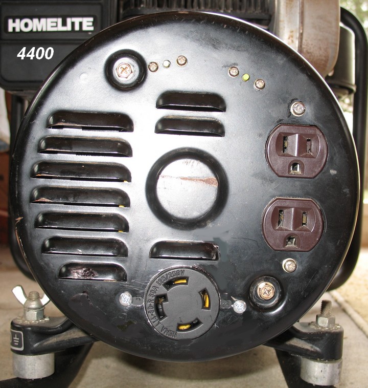
Homelite 4400
This generator used a single 6-15R for 240V output. It was replaced with a L14-20R. Both live lines were relocated to the new outlet. The neutral bonding wire was relocated to the new twistlock outlet.


Honda EB series generators with GFCI outputs will cause the breaker to trip when connected to some transfer panels. To correct this the neutral bond must be removed.
Check Honda Service Bulletin #20 for details.

 warrens@ns.REMOVE.sympatico.ca
Please email any comments or suggestions.
Hopefully this page will be of assistance. Feel free to link here and forward the site to friends or others who may be interested. Other than as noted all content is original. Please give proper credit if you borrow from here.
If you've found my site useful and would like to donate via PayPal to help keep it online please click the banner below.
Thanks
 Warren
 To determine if your generator uses a floating or bonded neutral perform this simple test. With the engine off, use an ohm meter between the chassis and neutral conductors in the outlet. If it indicates open circuit, the neutral is floating. A short circuit will indicate neutral bonded to ground. I don't recommend doing this to household circuits due to the possibility of exposed AC and damage to the meter.