
email me - warrenstone@eastlink.REMOVE.ca
email me - warrenstone@eastlink.REMOVE.ca
Click thumbnails to enlarge
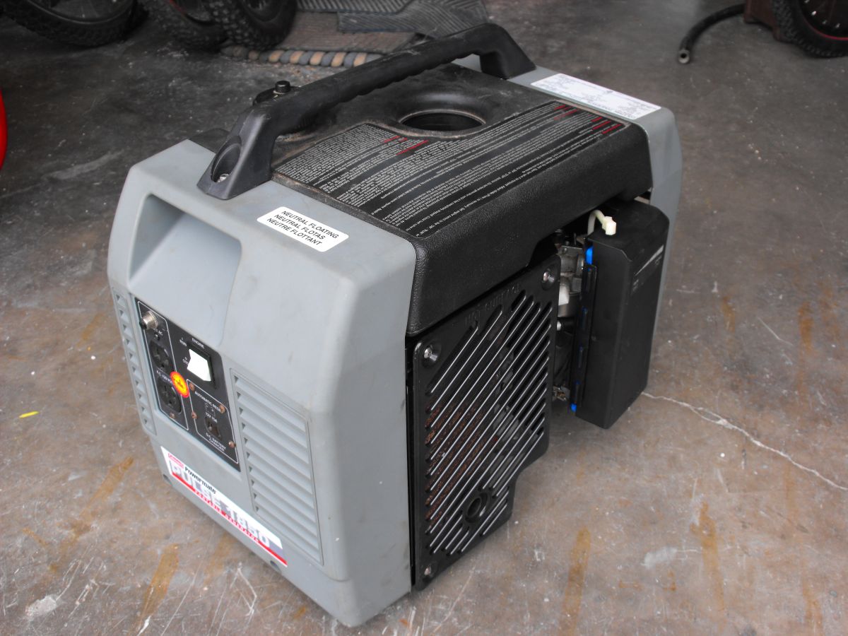
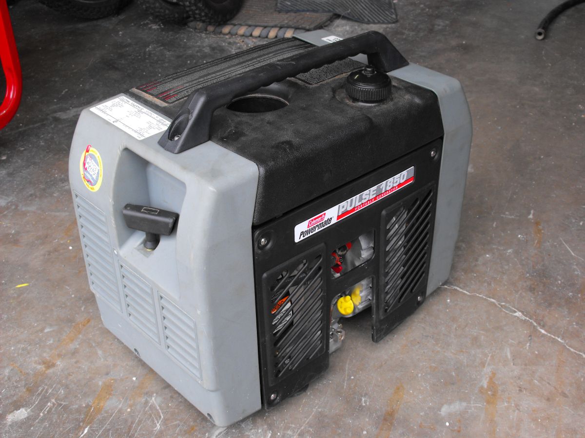
 This is the generator fully reassembled following repair.
I've had someone snicker at my going to this extent for what should be a simple repair job. I hope the web page and pictures may help someone with a similar problem. While I had the generator dismantled and the engine apart the cleaning and added work were relatively simple. It took about a week for parts to arrive, so the added effort created no furter delay in completion. It produced a much better result than a quick repair job.
I bought the generator because it wasn't working properly. The engine ran well but the output voltage was unsteady. The problem seemed to be related to inconsistant engine speed. I expected a spring to be missing or something else silly like that. As I started troubleshooting it became clear the problem was a bit more involved. The governor lever didn't have any tension regardless of engine speed. Something inside the engine had failed. The fun begins.
 In order to get at the engine, the entire generator must be dismantled. The plastic end covers come off, fuel tank, heat shield, and so on. The rotor must be removed from the tapered engine shaft before the engine casing can be removed. Removing the rotor is a two person job. The long bolt must be removed from the center of the rotor. The bolt at the other end of the crank needs to be held in place in order to loosen the rotor bolt. Remove the lock washer and put the bolt back in place. Leave the width of the bolt between the head and the top of the rotor shaft. Hold the entire engine vertically above the work bench, holding tightly to the rotor. Hit the rotor bolt sharply with a hammer to knock it loose from the tapered shaft. Be careful not to strike the side of the shaft as it will damage the bearing assembly.


Check the work bench. It's a piece of plywood over the top of my former Briggs & Stratton 5500W generator.
 Once opened up I found the governor lever had broken off and damaged the governor wheel. New parts were ordered.
 While waiting for the parts to arrive I carefully inspected all parts inside the generator. The engine seems in very good condition. No further problems were found and the cause of the governor failure remains a mystery. It was also an opportunity to clean everything. The casings and covers were loaded into the dishwasher. I removed as much oil and residue from inside the engine as possible and cleaned the outer case.
My wife doesn't bother complaining any more as she knows it's pointless... The dishwasher was none the worse afterwards.


Notice the metal gear on the main crankshaft has 21 teeth. The plastic camshaft gear has 42 teeth. The camshaft will turn once for every two turns of the crankshaft. This makes timing the valves easy. There are timing marks on both gears to ensure proper timing during assembly. Another interesting part of many small engines is the spark plug will fire on every rotation of the engine. It will fire at the top of the exhaust stroke and again at the top of the compression stroke.
When the parts arrived it was relatively simple to reassemble. Even so I had to take things apart along the way after forgetting a piece here and there. It took about an hour to put back together. Fortunately there were no parts left over at the end. The bearing at the end of the rotor was cleaned and regreased prior to assembly. New stainless steel screws were used to hold the side panels in place. It seemed like a good time to put in a new air filter and a new spark plug.
When everything was assembled the crank case was filled with synthetic oil. Pulling the starter cord felt normal and there were no unusual sounds. The fuel tank was filled and it was time to start the engine. It fired up without hesitation. The output voltage and frequency was monitored in order to properly adjust the governor spring tension. After a short warm up to allow things to stabilize the output voltage and frequency are right where they should be.
 I suspect that when the governor lever failed it caused the engine to rev very high causing a very high output voltage. This damaged the MOVs. As a result they start to conduct early, preventing full power from being available.
The original diodes are Motorola MR760, rated 1kV 6A.
Surprisingly, testing with a multimeter indicates the diodes are ok. However to play it safe they will be replaced with new NTE5817 diodes. Earlier 1850 generators used a 27kohm resistor in parallel with the diodes. Mine uses a zinc oxide varistor instead. It is labelled
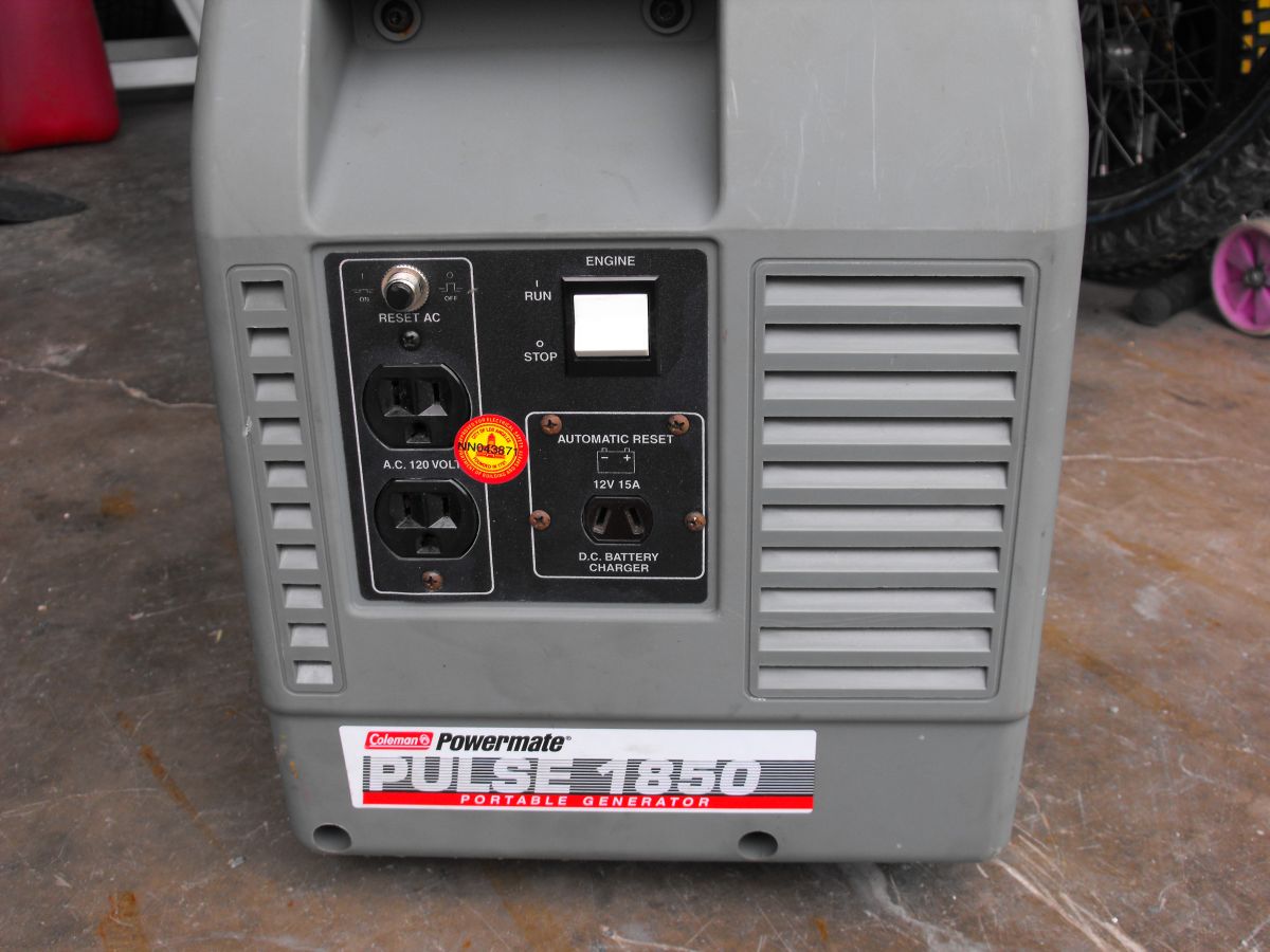
MDC Z511 110UL. It will be replaced with a Littelfuse V510LA40AP. The varistors and diodes can be removed from the rotor while it remains in the generator. They are accessible by removing the electrical panel as shown in picture 1850-7 (middle of five pictures) above.
I suspect that when the governor lever failed it caused the engine to rev very high causing a very high output voltage. This damaged the MOVs. As a result they start to conduct early, preventing full power from being available.
The original diodes are Motorola MR760, rated 1kV 6A.
Surprisingly, testing with a multimeter indicates the diodes are ok. However to play it safe they will be replaced with new NTE5817 diodes. Earlier 1850 generators used a 27kohm resistor in parallel with the diodes. Mine uses a zinc oxide varistor instead. It is labelled
MDC Z511 110UL. It will be replaced with a Littelfuse V510LA40AP. The varistors and diodes can be removed from the rotor while it remains in the generator. They are accessible by removing the electrical panel as shown in picture 1850-7 (middle of five pictures) above.
Before removing the diodes, mark on the rotor which side of the coil the cathode connects. Ensure you install the new parts the same way. I found out the hard way that the diodes must be installed in the same orientation as original. When installed backwards there will be no output voltage. Use a small amount of silicone sealant to hold the varistor and diodes steady inside the rotor housing. Any shaking or vibration will lead to eventual failure of the coil wiring where the parts solder together.
The 7.5uF 350V capacitor tests good.
I measured DC resistance of each coil.
Output coil measured between live and neutral outputs on the duplex outlet 1.2 ohms.
Rotor coils with the diodes removed 10.9 ohms, 11.1 ohms.
Coil in parallel with 7.5uF capacitor. Yellow wires (capacitor removed) 8.5 ohms.
The generator was bought as a toy and a repair project. It was sold a short time after the repairs were complete.
It does not use an inverter type output. The engine turns the rotor at 3600RPM in order to produce 60Hz AC. The output will be a sine wave, not a square wave or modified sine wave. I've seen far too many references to this generator producing square waves or telling owners to adjust the inverter which doesn't exist. It doesn't have electric start. There is no idle control or automatic voltage regulation and no low oil alert either.
Here are some of the manufacturer specs.
· Fully Enclosed to Help Reduce Noise
· Two 120-Volt AC Outlets with Circuit Breaker Protection
· 12-Volt, 15-Amp DC Outlet
· Rubber Feet Minimize Crawling and Vibration
· Model no. MPM0401850
· Max watts 1850
· Run watts 1500
· Output voltage 120V 60Hz
· Engine 3.5 HP Briggs & Stratton
· Fuel tank 1 Gallon
· Run time @ 50% load 3.5 hours
· Spark arrestor PA0650066
· Weight 68 lbs.
This is stamped onto the engine housing
Model 91412
Type 0120-E1
Code 01060534 (manufactured 2001)
Family YBSXS.1481HE 274454
Coleman Powermate 1850 Pulse
operator / parts list manual
Briggs and Stratton
engine manual