 04.04.2001
[MAX914]
-- About
-- Mechanical
-- Electrical
-- Computer
-- Old News
-- Software
-- RTOS
-- Todo List
-- Work Log
[AZ914]
-- T. Hannum
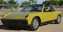
-- Brad's '70
--
[LINKS]
-- rennlist.org
-- all914.com
-- pelicanparts.com
-- paulweir.com
-- linuxdoc.org
-- epanorama.net
![]()
Computers, Microcontrollers &Digital Electronics
This page contains information and resources for the computer hardware. This is the digital electronics type area. Here you will find information about the motherboards, CPU's, memory, hard drives, microcontrollers etc that are used in the project. You will also find cross references to the Software and Electrica pages where applicable.
Resources:
Microcontrollers:
--my Linux-based PIC development world - Good page that shows some tools and uitilities for programming the PIC microcontrollers.
--David Tait's Links to Internet PIC Resources - This page was 'frozen' in May of 1999, but still had good links and relative information.I/O Hardware and Interfacing:
-- ... more to come ...
The Story So Far...
..... Now then the story starts like this... I was at one time planning on building a robot, and built a pretty nice aluminum frame to hold the boards and battery. The robot was never finished as I ended up purchasing a Hero 1 robot off E-Bay. Hero is gone now, but thats another story... anyway after getting Hero and another 914, I decide I knew what the new goal and function of all those motherboards was going to be, a Beowulf system for the 914. And so start project MAX914:
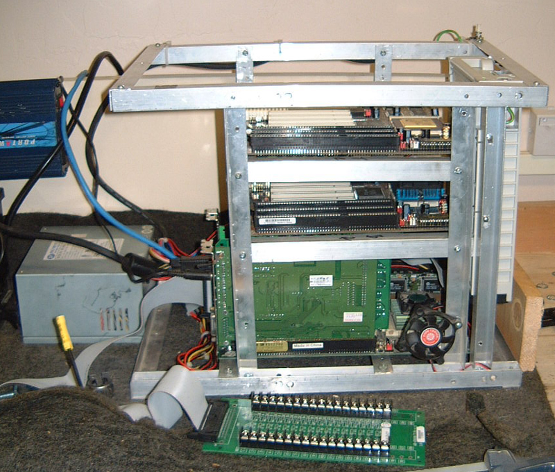
So this was the original configuration of the motherboards. I liked the idea, but unfortunately, it didn't fit well with the use of add on cards. Left and right risors for PCI or ISA run about $80 each from Fry's Electronics (careful what you purchase here its all used IMHO). But with this in mind, and the overall idea of how I wanted to design the case I went with a new format and layout shown below:
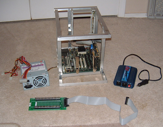
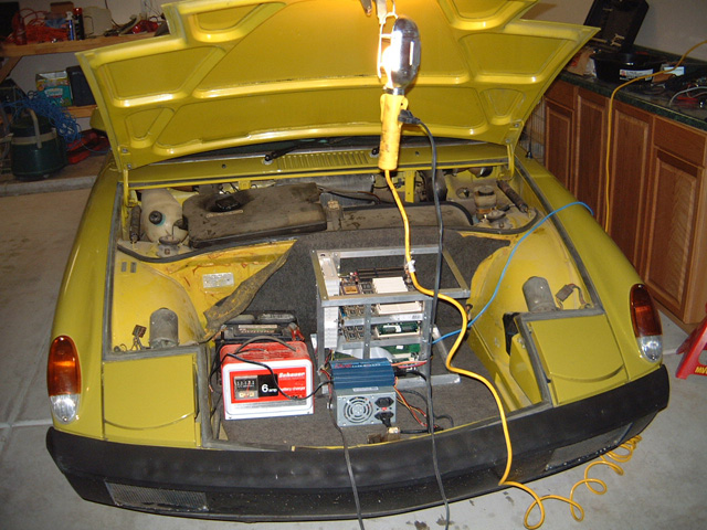
Here you can see the base frame with only one motherboard, the hard drives removable bay is at the top of the frame. You can also see the standard PC Power supply, a 300w Power Converter I got for $50 from Costco, and the end of the Analog to Digital converter card. This piece plugs into the card on the far right of the picture and offers 16 singled ended, or 8 differential inputs. This is our first an primary programming interface. The machine in the trunk of the car for the first test off the battery. I ran the system for 2 hours at a time between charges with this battery that is quit old... you can see the battery behind the charger. The blue cable is the 100BaseT ethernet, although 10 would work as well, I just happen to have 100's laying around from previous projects.
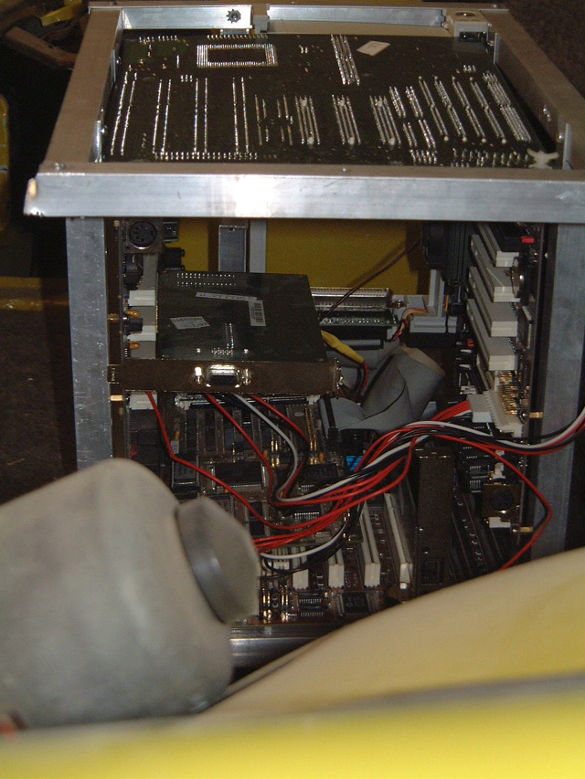
I am now working on a permanent mounting system for the computer in the front of the car. Check back for more in a few and see how I finally mounted the whole thing up front. I live in AZ, so I want A/C in the car. Max already has his pipes ran, so its just a matter of getting the rest of the pieces to put under that board instead of the spare tire.