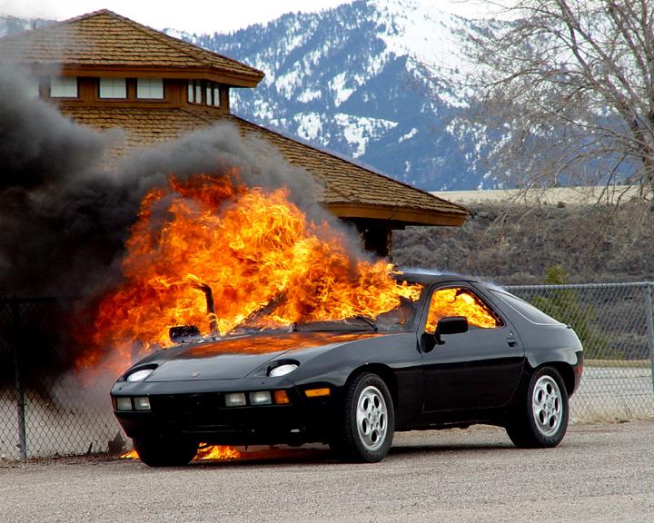
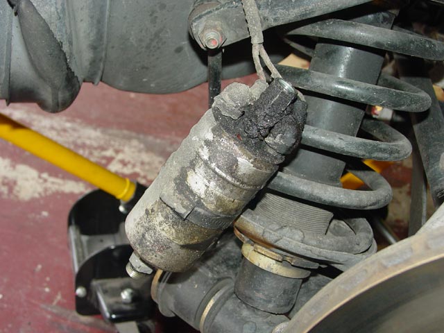
I had in the back of my mind the knowledge that my fuel lines were of unknown vintage. We've all heard the horror stories of what can happen if an aged fuel line ruptures, and I did not want this to be me:
Many of the fuel hoses on the '78 cars are NLA, for example the hose that runs from the first fuel pump under the tank to the second pump in the passenger side wheelwell. Roger at 928sRus has been working to spec and stock kits for the various MY 928s to rebuild fuel lines using existing fittings, new hose, and suitable clamps. Having the correct type of hose and the correct type of clamp is critical, especially for CIS cars that run at ~75psi+. Do not attempt to do this job with common low-pressure fuel hose or with worm-style clamps. You have been warned.
In return for providing Roger with details of exact material requirements plus a detailed writeup, he sent me more than enough bulk hose and more than enough clamps to do the job. It was too good of a deal to pass up.

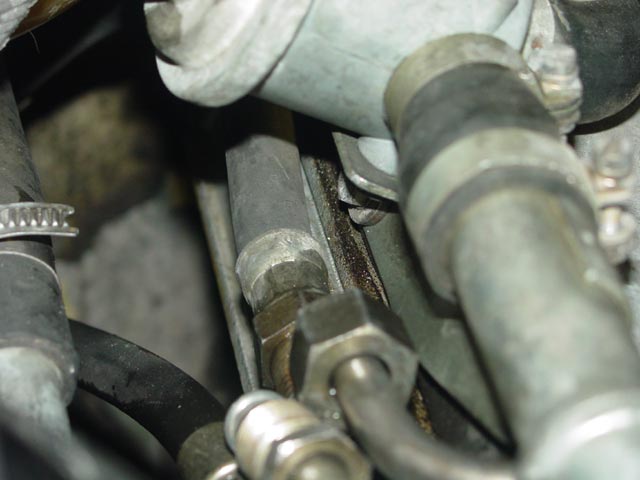
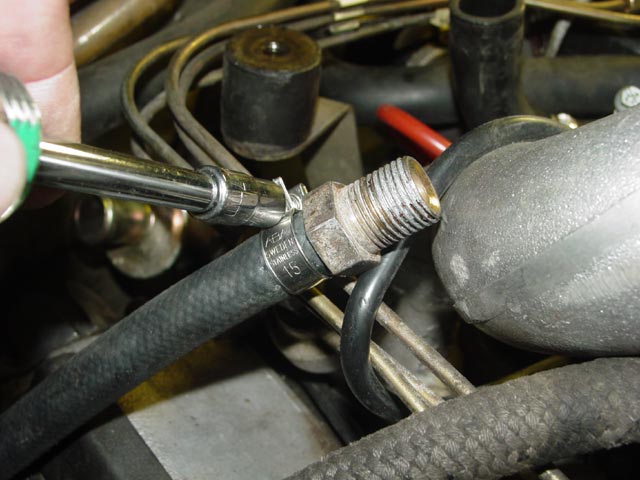
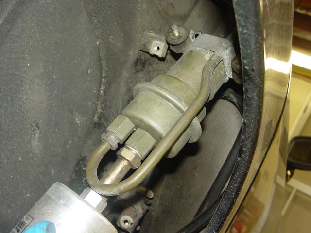
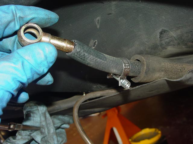
The front hoses were rebuilt in the process of completing my coolant reservoir swap, so there may be some duplication of pictures but the details rightly belong on this page. The first step was to pull the fuel pump relay with the car running to relieve pressure on the lines. I then broke the fittings loose with a little help from a squirt of PB Blaster.
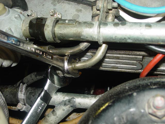
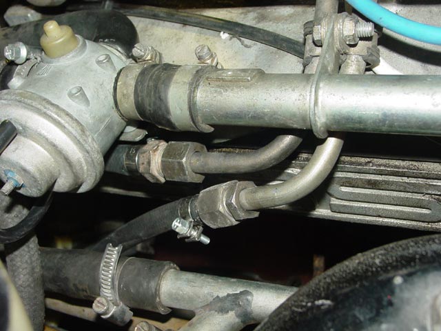
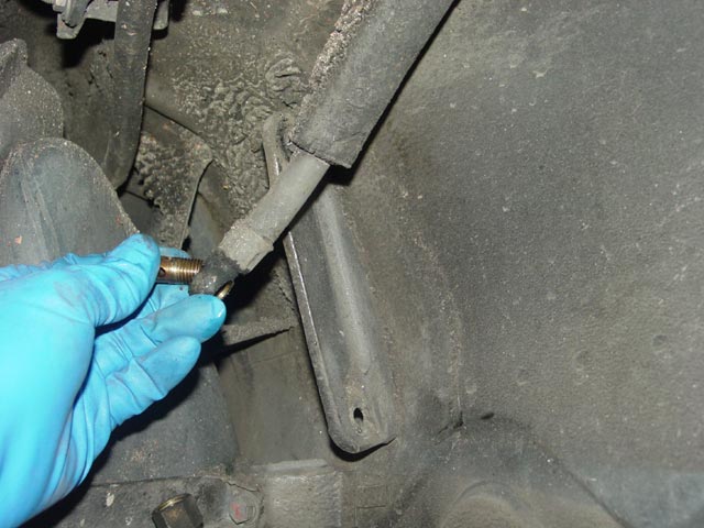
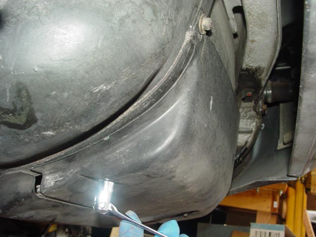
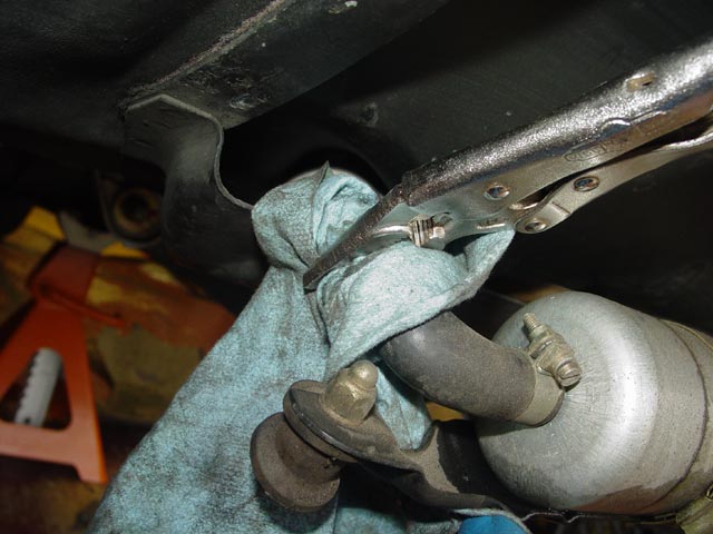
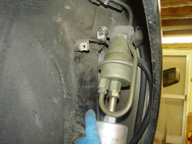
Here the upper fittings on both lines are broken free. To get to the lower fittings, I had to jack the car up and get to them from underneath.
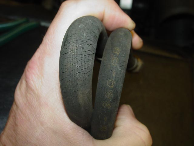
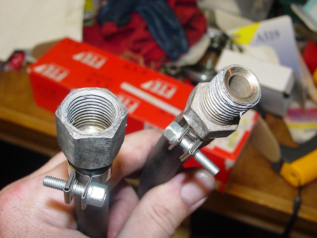
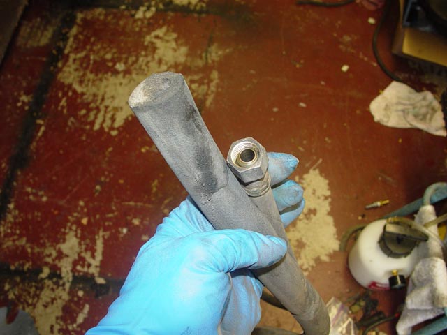
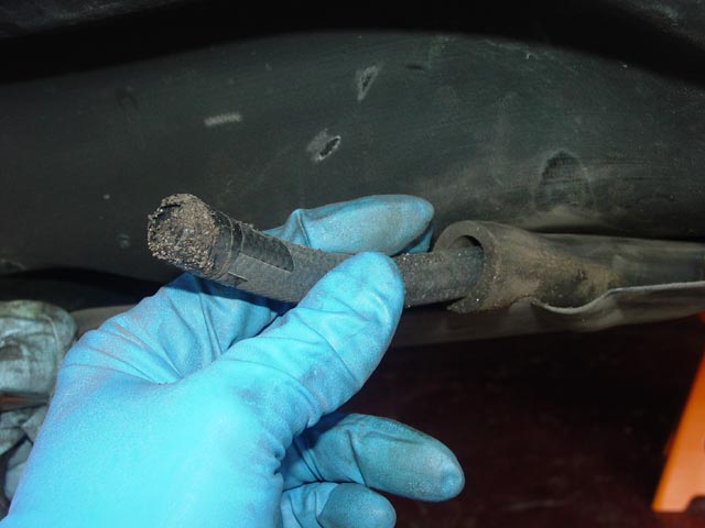
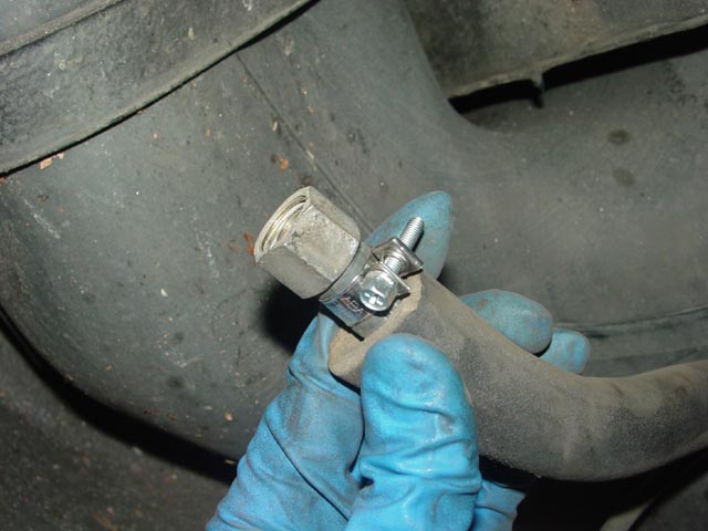
Here are the hoses as removed from the car. There are two hose sizes, with different fittings on each. If you rebuild the hoses one at a time there is really no way to get mixed up and do it wrong.
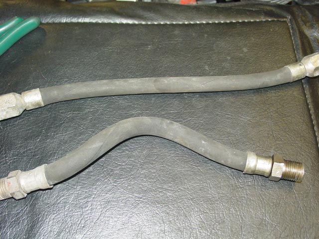
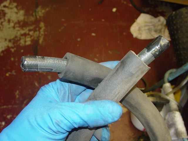
The hoses looked fine if a bit old, it wasn't until I had them out and flexed them a bit that I could see that the outer jacket was cracking. These lines were original, judging by the 1978 date code printed on the hose.
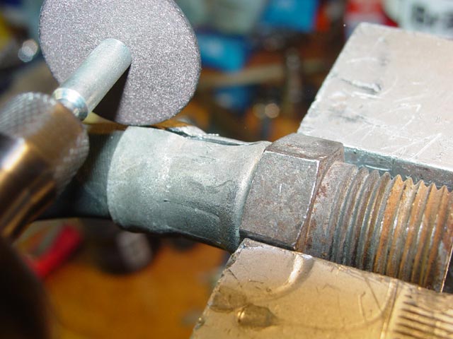
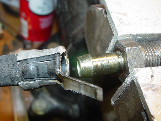
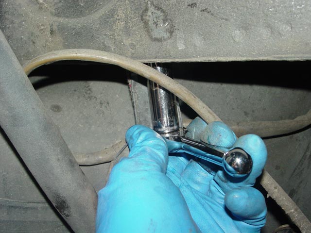
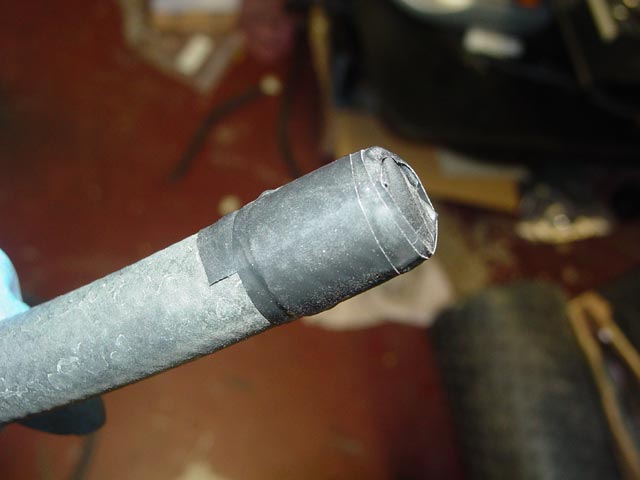
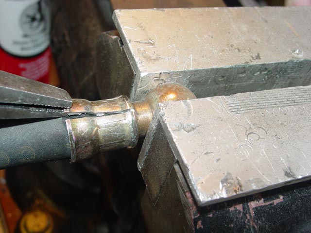
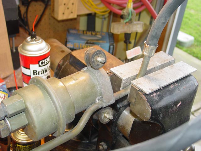
The first step was to cut through the ferrule with a Dremel using a #409 cutoff wheel. These cutting wheels are delicate and I broke several of them in the process, but fortunately they are cheap and they come in a 36-pack. I was very careful to control the depth of cut, since contacting the barb with the cutoff wheel would ruin it. I also did my best to avoid cutting into the net on the fitting, though this is less critical.
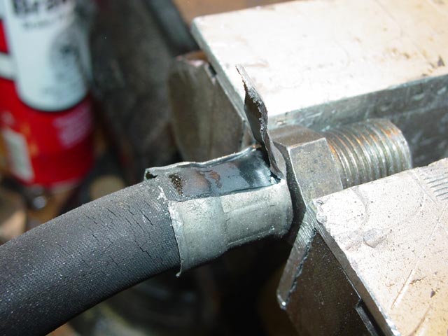
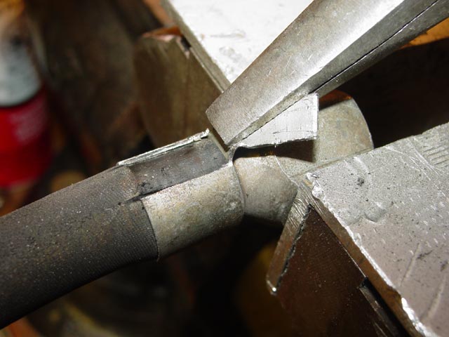
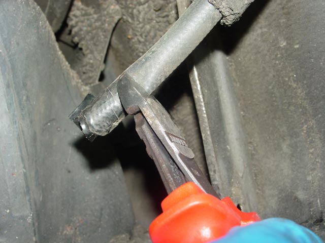
After cutting two slots in the ferrule, it peeled back easily with a pair of duckbill pliers.
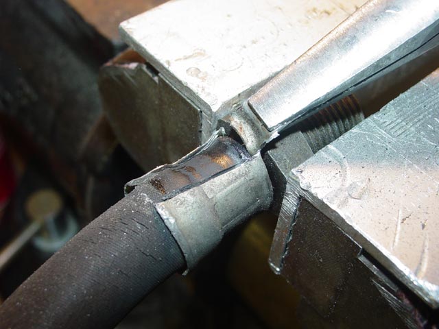
Gripping the piece that I had peeled back, I rocked it back and forth until it snapped free and I could loosen the ferrule.
With a strong pull and a twist, the hose came off of the barb.
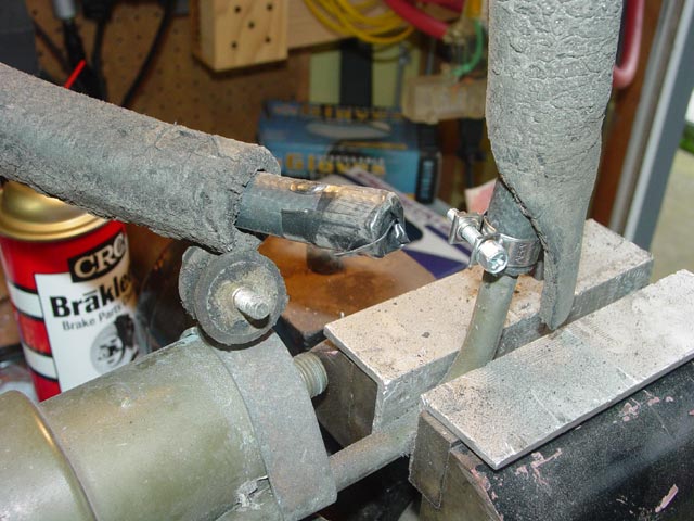
I used the same process on the pressure hose.
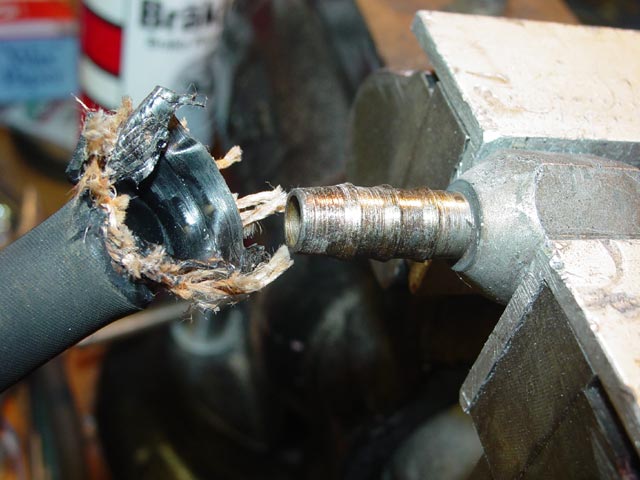
The smaller pressure hose has a liner that is especially tenacious. Thee outer jacket and cords came off easily enough, but the liner had to be pinched off of the fitting with the duckbill pliers, taking care to avoid marring the barb. You can see the plier marks on the liner in this pic.
I cleaned off the fittings with mineral spirits(carb or brake cleaner works just as well). Then I cut the end of the hose as square as possible and slipped it over the fitting with a little spit to help it along. It's a tight fit. I considered using WD-40 but decided that the mineral spirits in the WD-40 should probably not be left trapped between the hose and fitting. I think the hoses are pretty much spit-proof though.
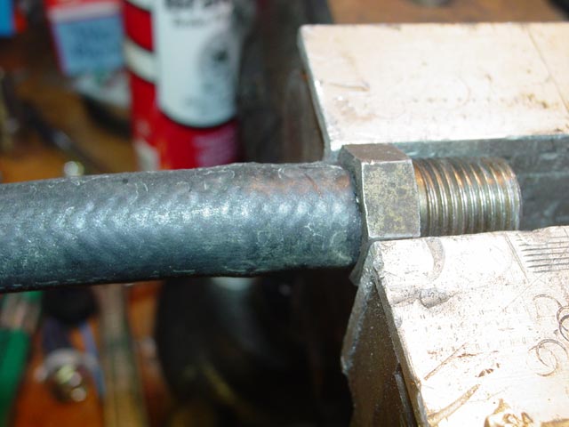
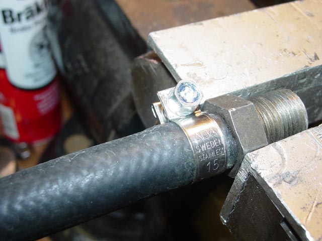
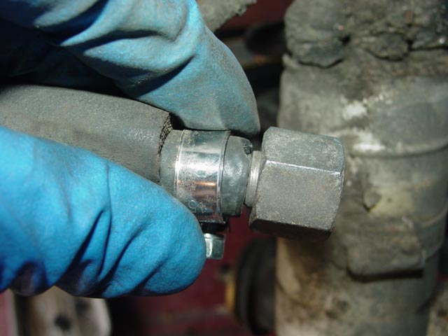
I then positioned the clamp so that there was a couple mm of hose visible between the clamp and the fitting, also making sure that I was not clamping over the barb that can be seen causing the hose to bulge. Note that there are two different clamp sizes, 14mm for the smaller hose and 15mm for the larger hose.
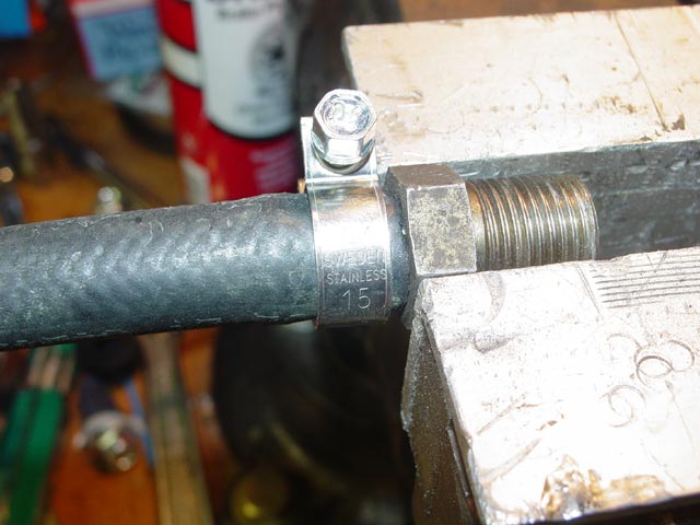
The clamps are not meant to be tightened until they bottom out. They just need to be tightened until you can see the clamp compressing the hose evenly all the way around. I recommend using a 7mm nutdriver instead of a phillips driver because it gives a more positive feel and will not push the clamp around on the hose.
I repeated the process with the other fittings, cutting the hoses to the same length as the originals(be sure to put the second clamp on before installing the second fitting on each hose). I have included the hose lengths and sizes at the bottom of this writeup. I also put a thin layer of anti-seize on the threads of each fitting. I made a reasonable effort to keep the anti-seize from getting into the fuel, though I can't imagine it would hurt anything.
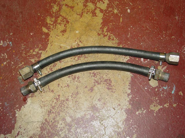
Here are the two rebuilt engine bay fuel lines ready for installation.
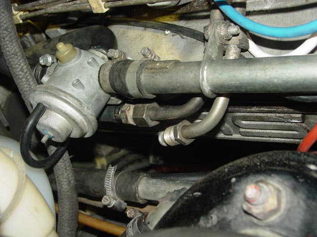
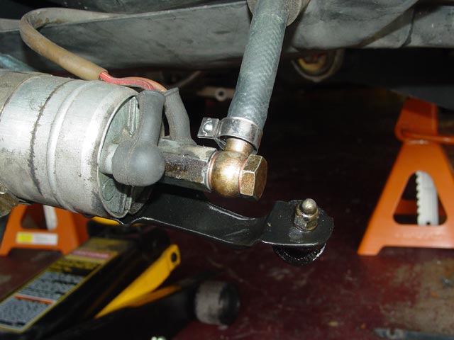
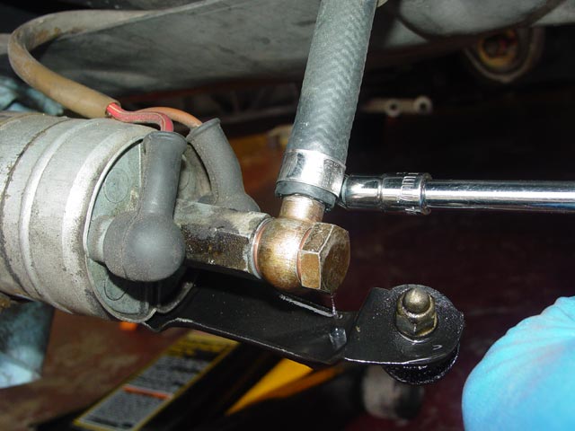
I installed the lines on the lower fittings first, and discovered that I didn't like the orientation of the clamps on the topside. The upper hose clamp screw interfered with the diverter valve mounting bracket, and the lower clamp screw interfered with the upper hose. It was easy enough to loosen and reposition the clamps. I could have attached them at the top first and maybe avoided this, but it was no big deal.
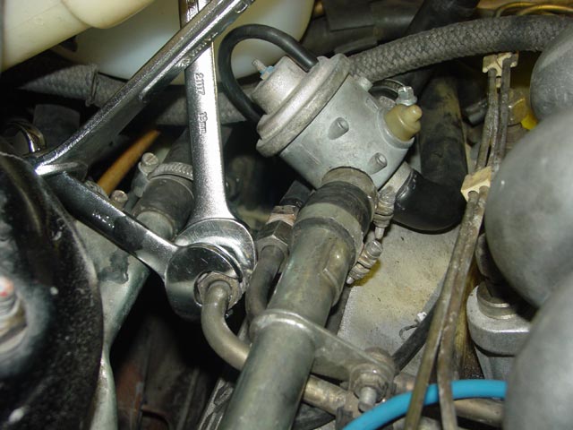
I hand-threaded the top hose to the hardline on the engine first.
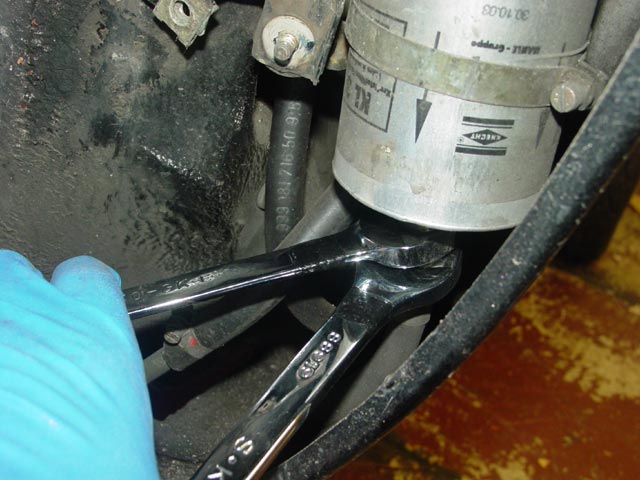
I then tightened using the two-wrench squeeze method, taking care that both wrenches were fully engaged on the nuts. If you do not counter-hold properly you WILL damage the hardline.
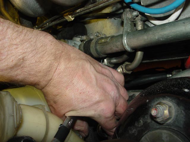
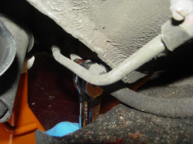
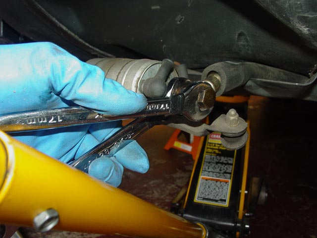
On the lower hose I could not get the two wrenches in a position to allow the squeeze technique to work because of the limited space, so I improvised with a large wrench adding leverage to the stubby wrench.
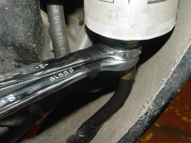
Here are the top fittings installed. I jumpered the fuel pump for a moment to check for leaks. On CIS cars you cannot leave the fuel pump running for very long because the injectors will spray a continuous stream of fuel if you do so.
I did the same quick check for gross leaks on the bottom fittings. Once I was sure there were no gross leaks, I started the car and let it run for a few minutes while checking for leaks. There were none, so at this point I was done with the lines in the engine bay.
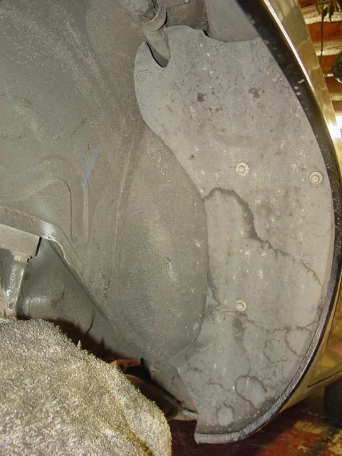
Moving on to the rear of the car, the liner in the front part of the rear wheelwell needs to be removed to access the accumulator and filter. I removed the three screws on the liner and maneuvered it out.
The second fuel pump will also have to be removed. Some early cars don't have a pump mounted here, they have the troublesome in-tank pump and the pump under the tank. You'll probably be asked to look in this area when ordering your kit to confirm which setup you have. I never did get around to replacing the plastic shield over the fuel pump. The crud seems to build up pretty fast because of the location, so rather than using a direct replacement I will at some point find a better way to keep this area protected.
After loosening the two mounting nuts, the shield slid off; it is slotted so the nuts don't have to come off to remove it. I removed the nuts and washers and let the pump hang free.
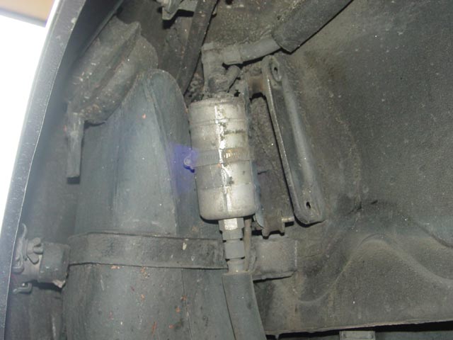
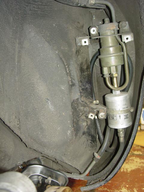
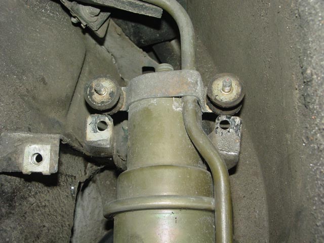
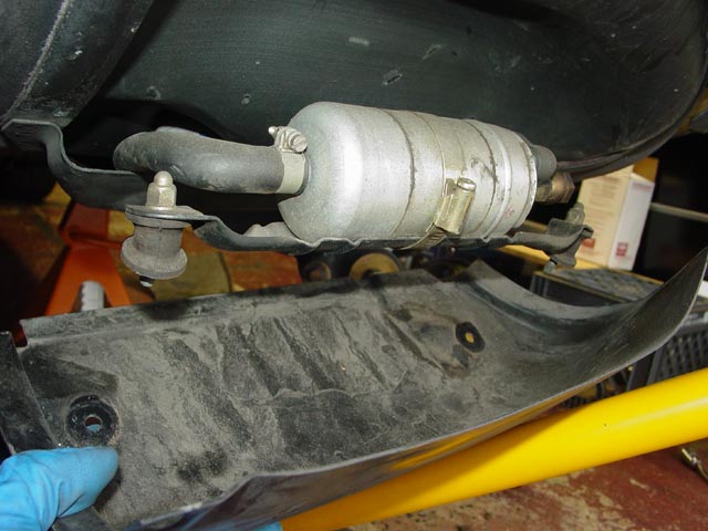
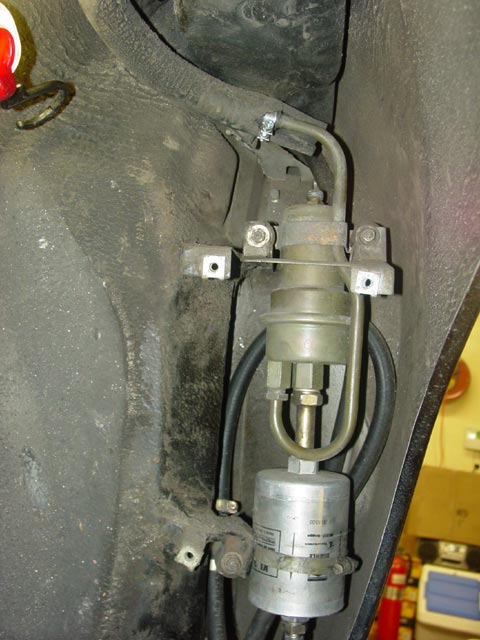
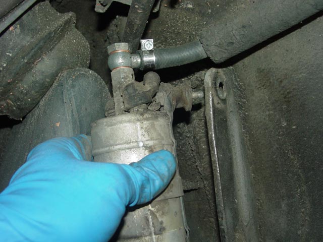
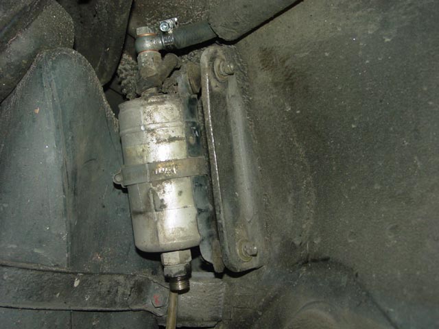
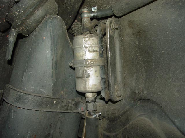
This is the plumbing that is exposed after removing the wheelwell liner. The green device is the accumulator, the silver canister is the filter. There is no need to separate the two for this project. I replaced the filter 20K miles ago, so I didn't replace it at this time.
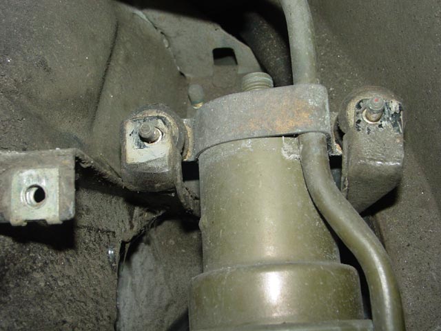
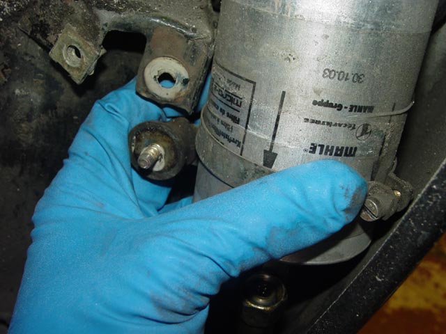
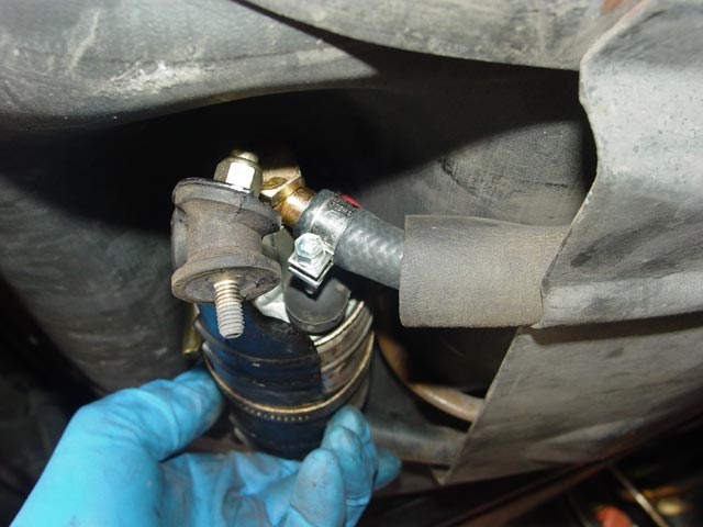
The two nuts at the top of the accumulator mount the accumulator and the bracket that helps hold the liner in. I removed the nuts and lifted the bracket off, noting its orientation for reassembly.
The accumulator is mounted to the back side of this bracket on rubber standoffs. It wouldn't move much at this point and I left it for the moment.
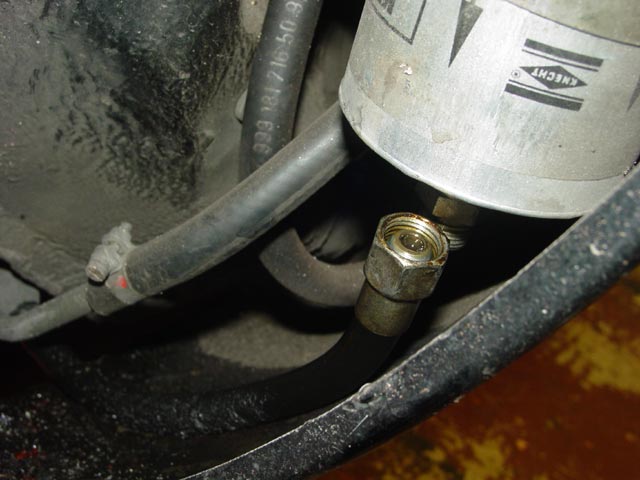
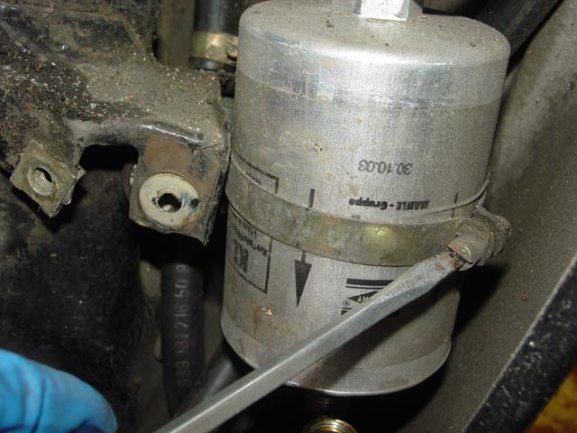
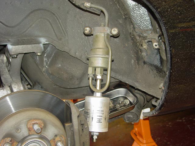
Next I removed the lower mounting nut at the filter and cracked open the hose fitting at the bottom of the filter, again using the squeeze technique.
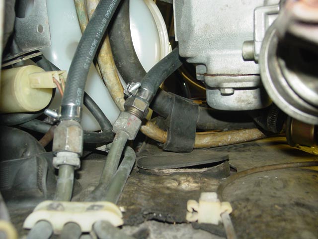
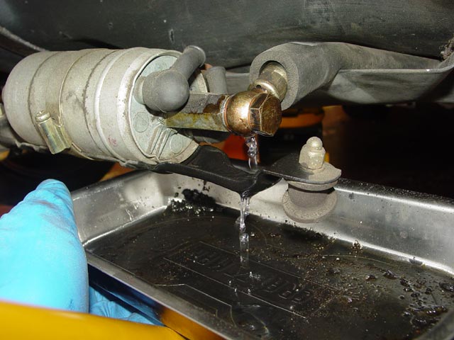
Since I had run the car after replacing the front lines, there was some pressure here even though I again ran the car and pulled the FPR. As soon as the fitting was cracked fuel started to run down the hose and the inside of the fender.
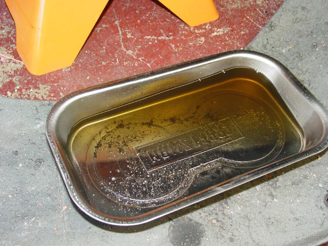
Fortunately I was expecting this and had a small pan handy to catch the fuel. Not much came out initially, but when I cracked open one of the rear fittings it broke the suction and more fuel came out -- so keep a pan under it.
I unscrewed the fuel line the rest of the way while managing the fuel that was dribbling out. It's a good idea to wear gasoline-resistant gloves at this point.
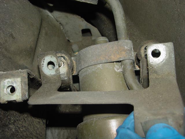
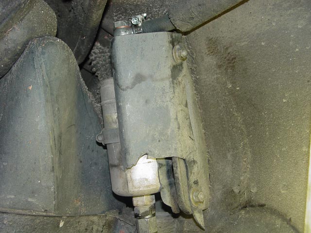
The filter and accumulator assembly would still not come out at this point. This clamp around the filter needed to be loosened to remove the mount.
Once it was loose enough, I slid the clamp and the mount downward and off of the filter.
Here is the mount as it came off, showing its orientation. The clamp drops over the mount on the portion closest to my thumb.
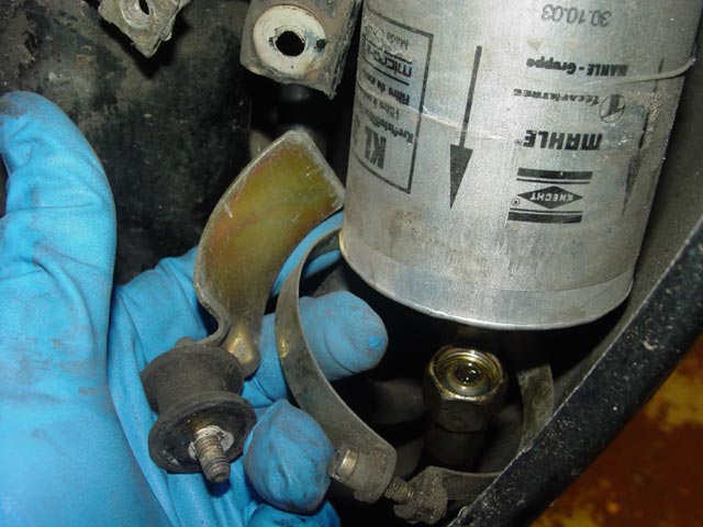
At this point I was able to disengage the top mounting studs and lift the accumulator mounting bracket over the bracket on the body.
Because of the way the hose on the accumulator is routed, I had to tilt the assembly and pull the filter out first.
At this point I just let the filter and accumulator assembly hang, with a pan underneath to catch the drips. I would have found a way to support it with no stress on the hose if not for the fact that I was in the process of replacing the hose.
Next I cracked open the fitting on the bottom of the pump. Once this was cracked open enough to admit air, the fuel in the accumulator and filter poured out of the filter into the pan.
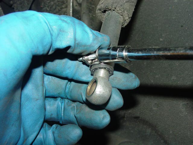
Once the fuel had finished draining, I removed the banjo from the top of the second pump.
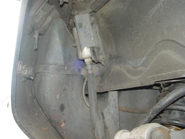
I hung the pump from the rear coil using one of the rubber standoffs. I ended up moving it around behind the swaybar, but this was a good place to hang it for a moment. I didn't want to put any stress on the wires.
I recovered the banjo bolt and set it aside for cleaning. All crush washers were discarded.
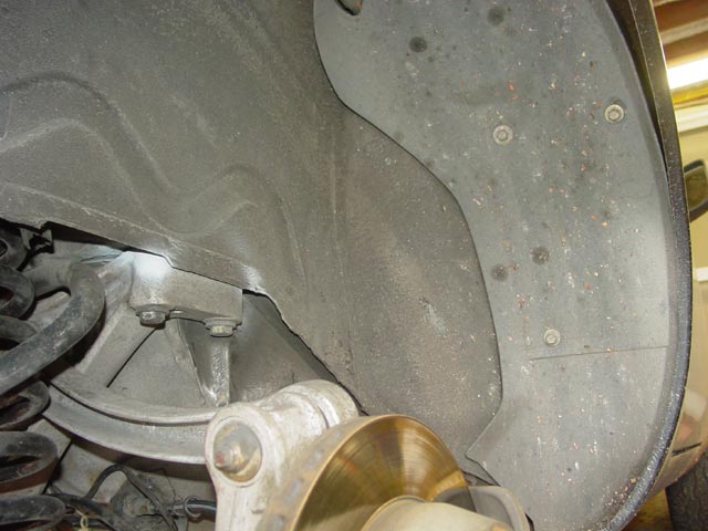
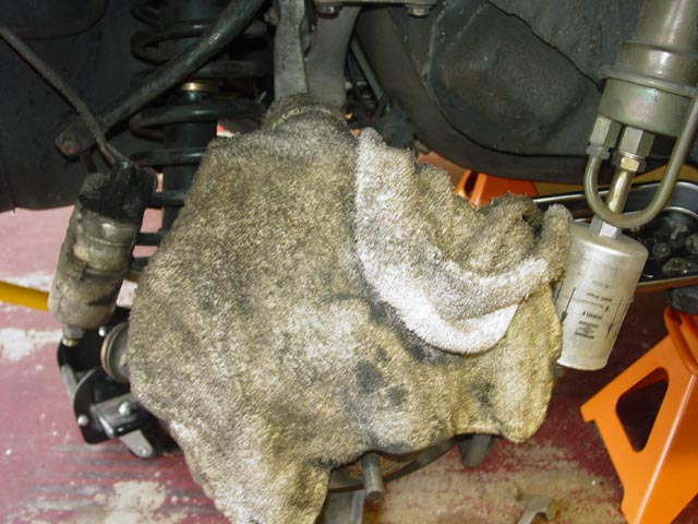
I covered the hub to keep crap from the wheelwell from raining down into it. Also, as I mentioned I moved the pump back behind the swaybar before performing the next step.
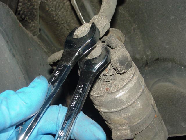
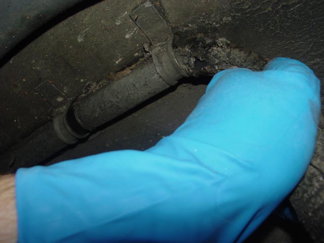
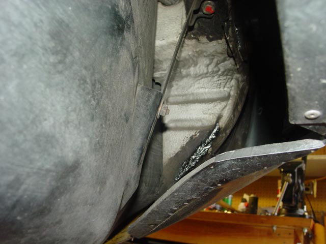
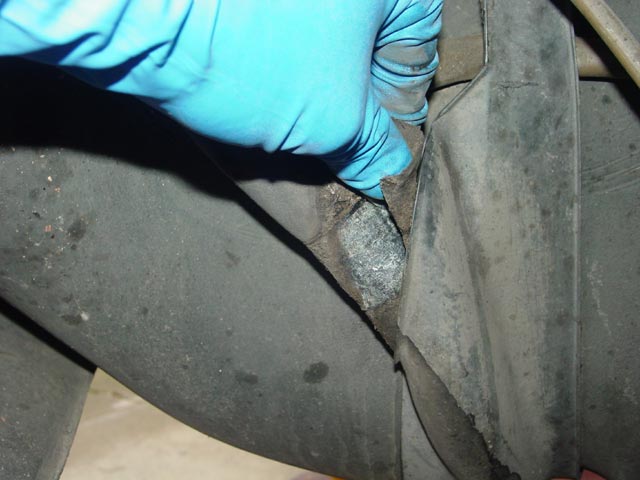
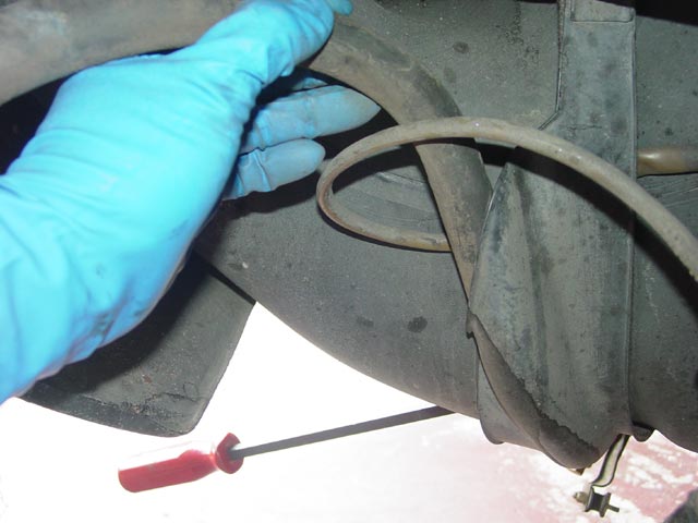
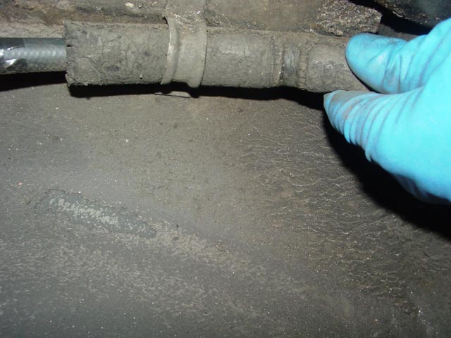
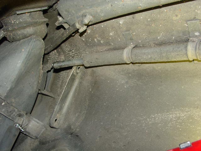
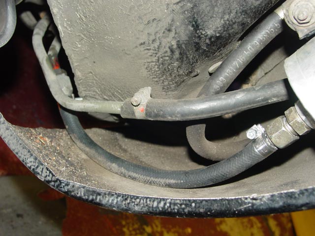
The hose that crosses under the expansion tank has collected a lot of crud over the years, so I worked the hose loose from the crud and brushed enough of it away that I could move the hose around.
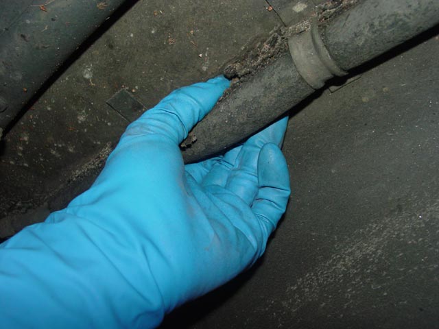
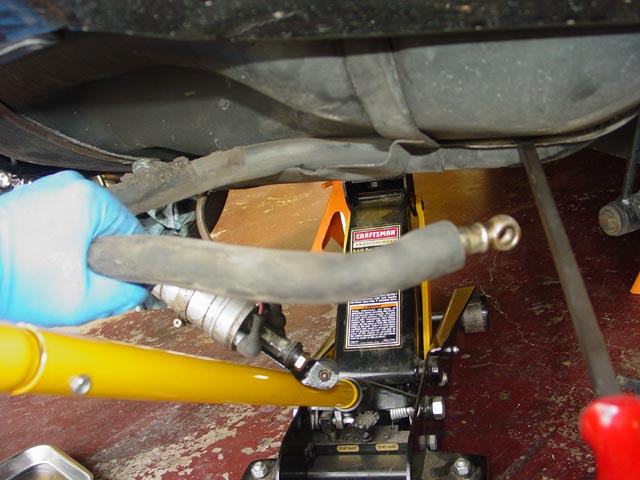
At this point I started pulling the fuel line out toward the accumulator. In the pic it looks like I was pulling down, but I was twisting the hose to a right angle and pulling it forward. The insulation around the hose looked worse than it was. Maybe 5% of the outer layer of the insulation had degraded. I didn't bother trying to replace it, I figured it would be good for some years.
After a little tugging and persuading I had the accumulator and middle hose out. I also had a mess.
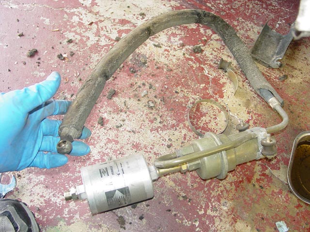
I finished removing the forward fuel hose There wasn't much fuel to drip out, but enough to merit having the pan under it.
Of the three hoses at the rear of the car, this was the only one that was of the smaller diameter.
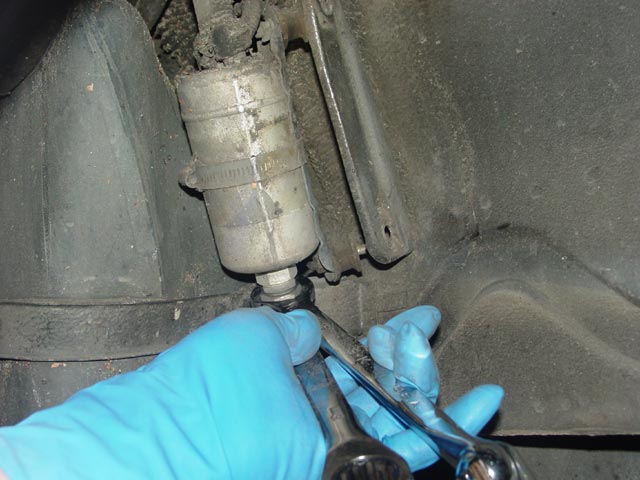
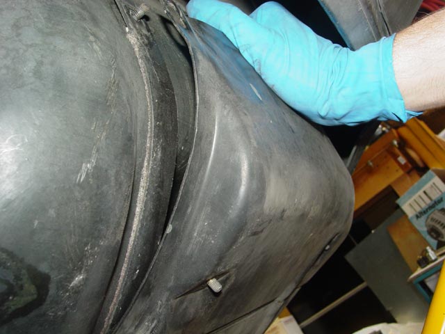
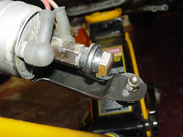
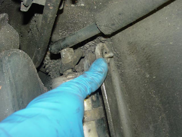
Next, I removed the cover over the fuel pump. The mounting is different than on the later cars. In my case the pump mounts to the cover via the nut that the wrench is on and the nut just beyond my middle finger. One of the two upper nuts is visible at the top of the frame.
The second upper nut is a bit harder to get to because of the way the bumper cover wraps around, but it was not difficult to get to.
With all four nuts removed, I pulled the rear edge of the cover off of the studs. Once free of the studs, there is a lip on the lower, forward edge that engages with the tank mounting cradle. The cover needed to be pulled rearward to disengage this lip and it dropped free.
With the cover off the fuel pump hangs from the inlet and outlet hoses.
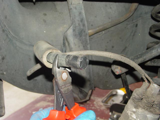
I used a pair of needle nosed vice grips padded with a paper towel to squeeze the inlet hose shut. If your inlet hose is not pliable you should instead drain the tank and replace it.
Next I cracked open the banjo fitting.
I had a pan handy to catch the fuel that dripped out of the pump and the rear hose.
The vise grips did not seal the hose 100% so I reinstalled the banjo bolt with a couple of rubber grommets to temporarily stop the drip.
In order to free up the rear hose, I loosened the front passenger side tank strap. I didn't completely remove the nut, I simply backed it way off.
On my car part of the fuel pump harness was taped to the fuel line. I pulled the hose forward a bit and removed the tape.
To free up the hose some more I inserted a prybar between the strap and the tank. There is little risk of damaging the tank this way, but be careful anyway. Note the tip of the prybar facing away from the tank.
At this point I was able to remove the rear hose by simply giving it a firm, steady pull. No drama.
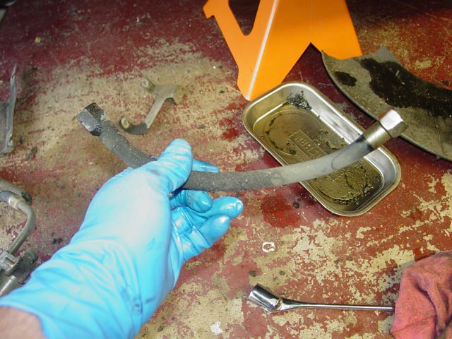
Here is the rear hose out of the car.
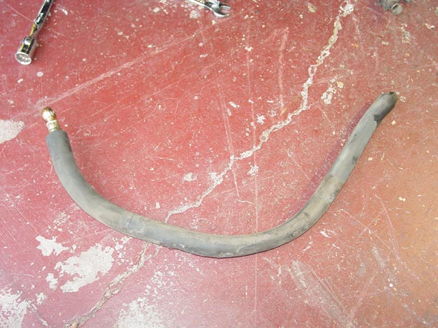
I then pulled the hose out of the insulation. Again, no drama. It came right out.
Each of the rear hoses was initially cut 2" longer than the hose it replaced. I then taped the ends before pushing the hose through the insulation.
Here is the rear hose with insulation, ready to install on the car.
I threaded thee rear hose in from the top, not being one to try to push a rope uphill...
Without the tape, I would have had an ugly mess to clean up. As it was I only needed to wipe off the end and remove the tape.
I removed the banjo fitting from the old hose using the same method as I used for all of the fittings. Not: Do not clamp a banjo fitting in a vise this way unless you have soft jaws on the vise!
I then placed a 15mm clamp on the hose noting the orientation of the screw and inserted the banjo fitting in the hose. A little spit on the fitting made it fairly easy to do.
With the banjo fitting loosely assembled with new crush washers, I moved the clamp down into position.
I tightened the clamp to the same degree as the others, just enough to visibly compress the rubber.
Next I worked the hose back into the insulation and eyeballed the location of the banjo fitting so I could tighten it into the right position, counterholding at the hex on the fuel pump output port. Once this was tight I removed the vice grips from the suction line. I meant to add a check valve to this connection, since I suspect that the internal check valve in the pump is not holding pressure. I didn't realize when I ordered the check valve that it will not work with a bolt; I needed a nut for this fitting. More on that later.
I cut the extra 2" off of the end of the hose that connects to the second pump.
Like the other fittings, after removing the fitting and cleaning it up I put the appropriate size clamp on the hose and pushed the fitting into the hose.
After determining how I wanted the clamp oriented I tightened it down. Here is the finished rear hose.
The middle hose which is attached to the accumulator was no different than the others and was refreshed using the same steps. Cut the ferrule, remove the old hose, Install the new hose with the appropriate clamp.
I taped the other end of the hose(cut a bit long) and inserted it through the insulation. I left the clamp a bit loose until I was sure how I wanted it oriented.
I then threaded the hose back through the loops in the wheelwell. It needed to be pulled along and massaged a bit but overall it went in very easily.
With the hose almost completely threaded through the loops, I hung the accumulator on the top studs and fine-tuned the position of the hose and the clamp on the accumulator side.
Once I was happy with everything I mounted up the accumulator("reverse of disassembly"), installed the liner bracket, lower mount and all mounting nuts, then tightened the hose clamp.
As planned, I had a little extra hose at this end. Before proceeding I tucked the rear hose under the body so junk wouldn't fall into it.
I held the rear pump in position to gauge where I should cut the hose.
I didn't bother to remove the tape, I just cut the end of the hose off...
...and installed the cleaned-up banjo fitting.
A small amount of debris had made its way into the pump. I inverted it and sprayed carb cleaner up into the outlet with a snorkle to clean it out, and made sure the sealing surface was clean. I wasn't too worried about the dirt on the outside of pump, I'll deal with that after I find a way to keep dirt from getting flung up there.
Next I threaded the banjo bolt in finger-tight with new crush washers, hung the second pump and installed the nuts and washers loosely, just a couple threads to keep it from falling.
Then I tightened up the banjo bolt, counterholding at the hex on the fuel pump output port.
Next I cleaned and dried the threads on the pump inlet and added a thin film of anti-seize. I then installed the rear hose on the pump inlet, counterholding by using the "squeeze" method".
Finally I rebuilt and installed the small diameter front hose using the methods described above. At this point I was ready to test for leaks. I jumpered the fuel pump for a few seconds and checked for gross leaks. Finding none, I started the car and let it run for a few minutes, checking all fittings and joins for leaks.
Having found no leaks in the system, I proceeded to button it up. I slipped the cover over the second pump and tightened the mounting nuts.
I reinstalled the liner in the front of the wheelwell, and with that I was finished for the weekend. Mission accomplished!
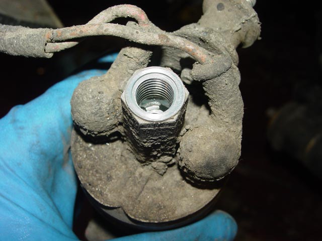
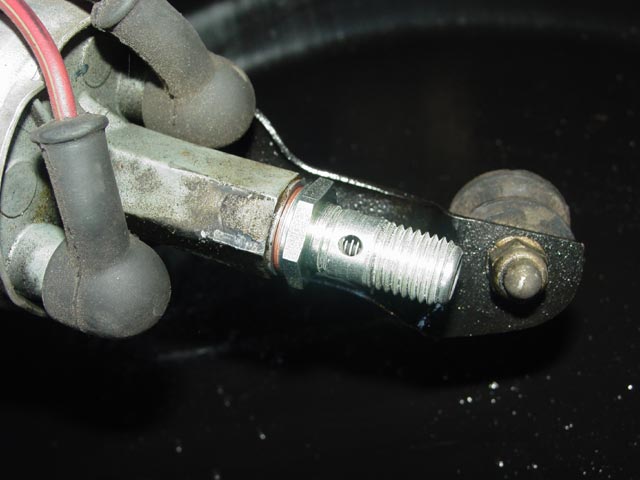
I went back in to install the check valve the following weekend, after I received the nut. First, I installed the check valve using a new crush washer, and tightened it while counterholding the hex on the output port.
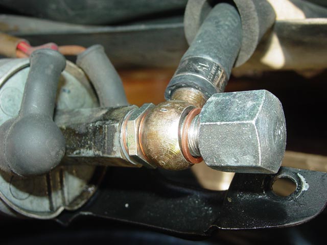
I had to remove the rubber standoff to gain clearance for this next step. I put a new crush washer followed by the banjo fitting then another new crush washer over the check valve and threaded the nut on.
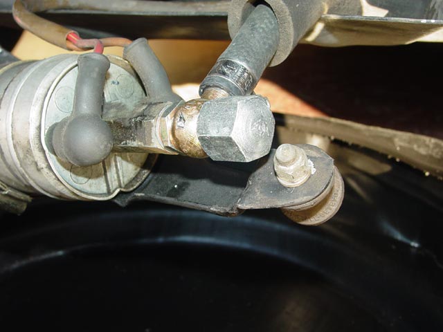
I torqued the nut down and reinstalled the standoff. I just finished this yesterday and it's too early to tell if it has helped. The problem I'm trying to solve is that sometimes when the car heat soaks and sits for a half hour or so, when I try to start it it fires and dies. On the next attempt it starts fine. We'll see if the check valve helps. if not I may have a leaky injector, WUR or regulator.
Below are the details of the parts I needed to rebuild all soft fuel lines except for the return hose to the tank.
- Clamps Needed:
- 4ea. 14mm
- 6ea. 15mm
- Engine Bay Hoses:
- Large Diameter: 9"
- Small Diameter: 10"
- Rear Hoses:
- Rear: Large Diameter, 27.5"
- Mid: Large Diameter, 27"
- Front: Small diameter, 9.5"
