I did considerable research into trying to make a high-output Delco alternator work on my car. Some Rennlisters, 928FIXER and toofast928 had had some success with installing Delco CS130 alternators on their cars. 928FIXER had posted his success story, then some time later Tony(toofast928) posted a thread indicating that he had done it too, and he had very impressive results with it. I attemted to make a Delco CS130D work, a more advanced, higher output unit with better bearings, cooling, etc. In the end it didn't work out because of my small ~5" crank pulley. It simply didn't spin the alternator fast enough to charge at idle. So, that project is on hold while I look into larger crank pulleys. I've posted the research I did on the subject down below, in the Delco section of this page.
So... what DID work, was getting on the horn with 928 International and getting hold of the correct replacement alternator, the shroud and the gasket. I tried a more local member of the Big 3, but their delivery time was far too long and I was sick of having the shark up on jackstands for what was to have been a fairly simple project.
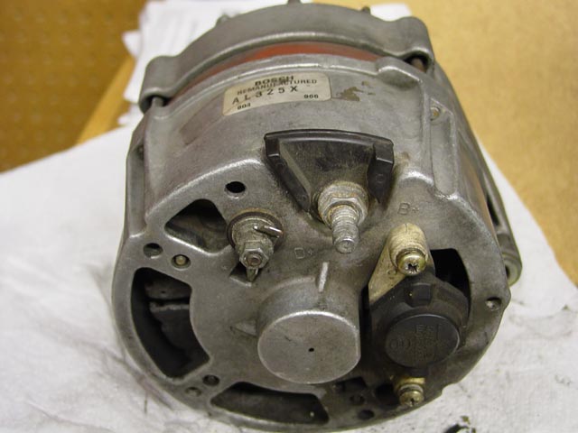
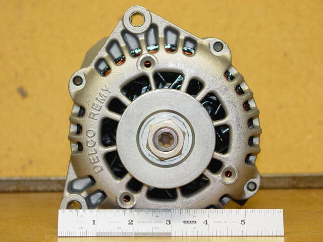
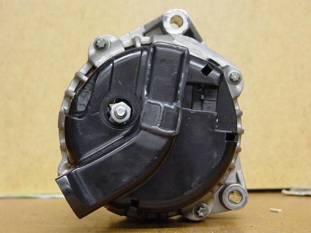
Below is the alternator that was on the car when I bought it. Mark Anderson tells me that from my description of it, it's probably an Audi 5000 alternator, a fairly common swap from what he sees. The sort of oily dusty film that is visible around the regulator and inside the openings burnt to a crispy brown on the back of one of the diodes, which accounts for the low charge voltage I was seeing -- at least one diode shot.
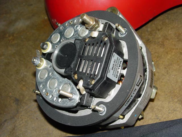
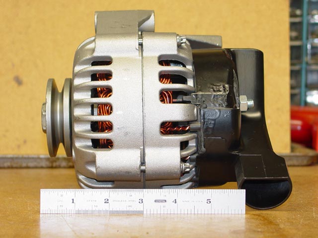
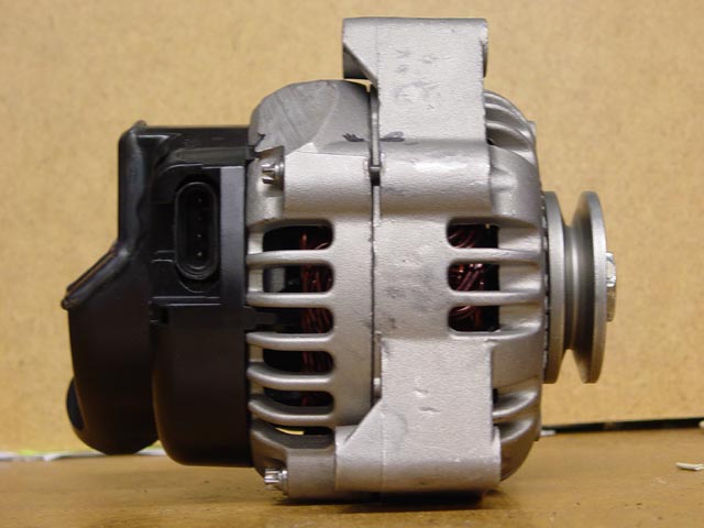
This is the replacement that I picked up from 928I. It's a Valeo A14N71 -- Apparently this is the French Company that bought up Paris-Rhone. Clearly this puppy was never intended to be run without a cooling shroud, as there is nothing directing cooling air over the diodes. All of the warnings I've heard on Rennlist about the importance of having the alternator shroud and plumbing makes a lot more sense now that I see the original alternator design. At first glance though, it's not obvious where I should connect the small wire that goes to the dash light. In this pic, the longer stud that goes to the top of the right-hand diode assembly attracted my attention... I thought it must be long for a reason. But the stud at the bottom of that same diode assembly looks like a connection could go there as well.
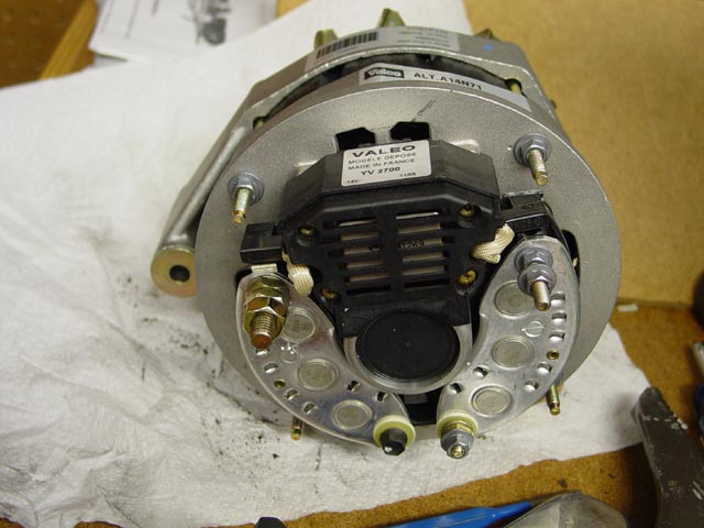
So it seemed that the obvious thing to do was

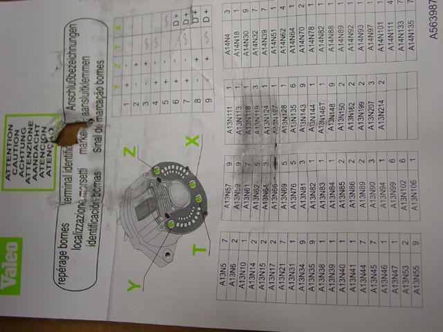
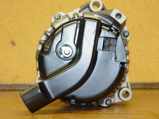
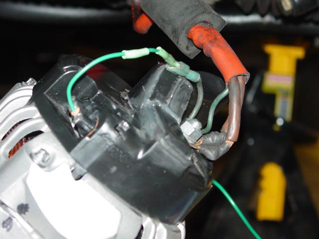
See anything strange? Anything missing? How about a reference for the A14N71 alternator?
 Well, I took another look, saw that the X terminal is usually the lamp circuit if anything, and the Z terminal is usually + or -. A quick check with the multimeter and Z turned out to be case ground. So, problem solved, I put my blade-to-ring terminal adapter from the old alternator on the X terminal, and removed the extra nut from the Z terminal.
The new alternator was provided with a woodruff key, but the pulley on the old alternator did not have a keyway. I decided that it was important enough that I cut a keyway in the old pulley myself. I didn't take pics of that operation, but basically I made a couple cuts with a thin sawzall blade, used the sawzall to chew out the excess between the two cuts, then cleaned it up with a thin file. I ended up making a pretty decent keyway that's only ~0.020" wider than the key. After that, I installed and torqued the pulley in place.
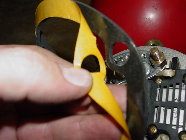
Next I installed the gasket. It has adhesive on one side, so I peeled off the backing and stuck the gasket to the alternator.
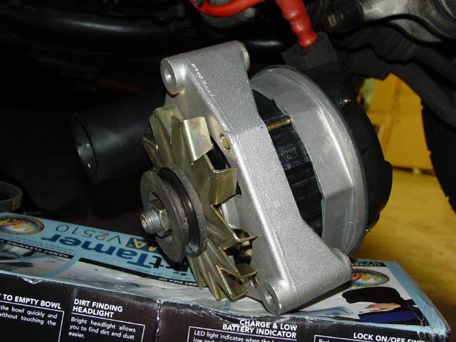
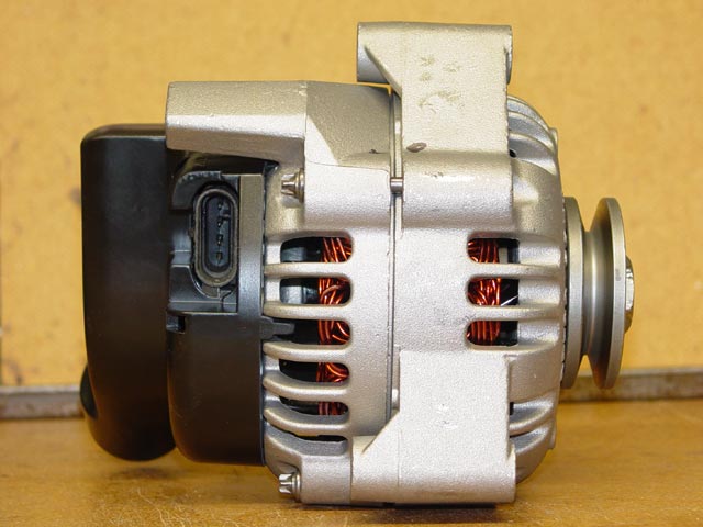
So here's the alternator, ready to begin hooking up the wiring. I have been under this car so many times, pulling and replacing the alternator, that I could probably do it in my sleep.

Since I had never seen the backside of the correct alternator before, I spent a little time fooling around with the shroud, seeing how it should be oriented and where that left the passthrough for the wiring. I settled on this location, cleaned the connectors and applied Stabilant, then tightened the B+ terminal nice and snug.

Next, I installed the cooling shroud, using stainless M5 nylock nuts & flatwashers. Careful not to overtighten... it will be obvious when you get to the point where the gasket is fully compressed, and especially with nylock nuts there is no point in going further.
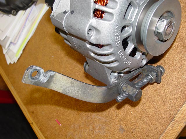
So here it is, all ready to mount up....
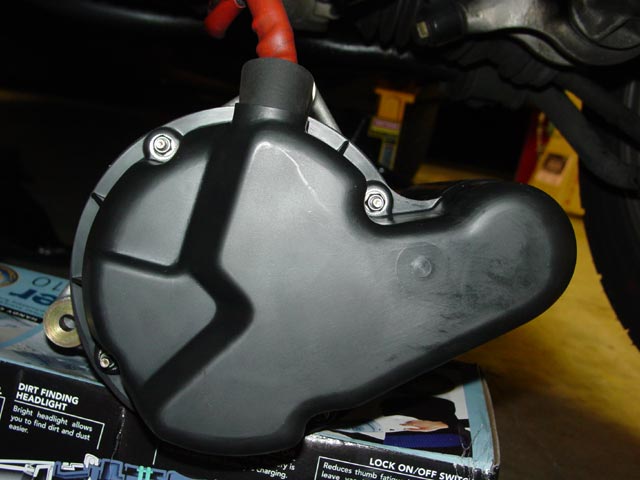
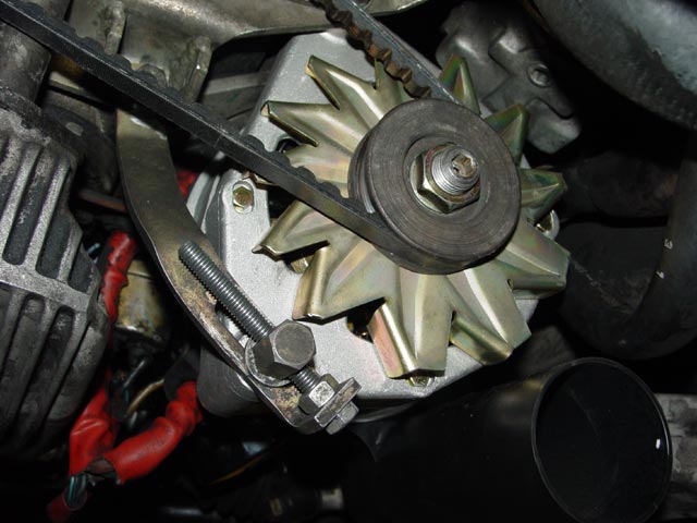
And here it is all mounted up, with a new belt.
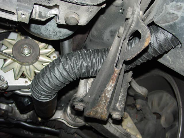
I found a source for quality, neoprene-impregnated canvas duct, OldCarStuff.com. I bought 2" duct which fit snugly inside the alternator shroud, requiring no hardware. The 2.5" duct would fit around the outside of the shroud, like the original, but had purchased this size to go with fittings I had planned to use on the Delco conversion -- and I lucked out that it worked on the original shroud.
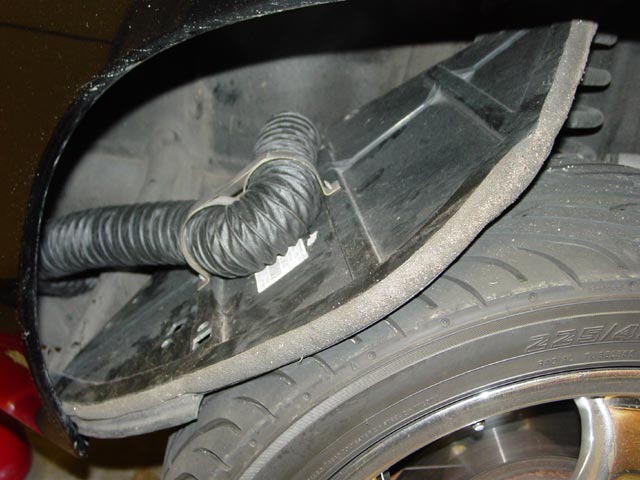
Here is the other end of the duct, routed as it should be to the bracket on the inside of the fender liner.
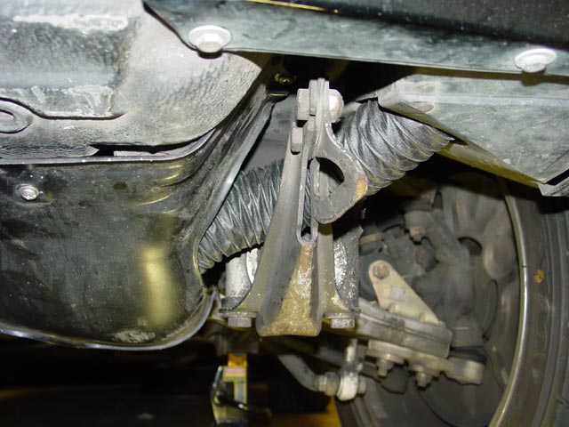
And here it is, with everything buttoned up and the belly pan in place. It made for a very clean install.
Overall this alternator performs very well. If the battery is discharged at all, it runs right up to 14V, then once equilibrium is reached it stays around 13.7 volts. With all of the lights on, plus defroster, it runs around 13V moving down the road. I have seen it put out 90 amps just off idle, though at idle it seems to be good for about 45 amps tops. Not a spectacular result, but absolutely acceptable for now. I really would like more capacity, but with this in place I am in no hurry and can take my time exploring other options.
Delco Alternator Info:
So here is the Delco CS130D Alternator.
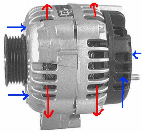
As you can see from the diagram below, air is pulled in both ends and blown out the sides. The regulator and diodes are the most heat-sensitive components, so I decided that the best course of action would be to try to use the original 928 alternator cooling duct setup to bring cool air to the alternator. At first I was ready to fabricate one up from plastic pipe fittings attached to the original shroud, but I was told that there was a ducted shroud available for this alternator so I decided to pursue that approach.
It was a bit of a pain to find the ducted shroud -- one application is 98-2002 5.7l Firebirds. I assumed from the shape of it that there must be some sort of ductwork and D-shaped connector that mates up with it, but my efforts were fruitless. Finally I got a look at one installed on a well-maintained Firebird, and I found that there is no ductwork, the shroud simply picks up engine bay air a few inches further from the manifold than it would without the shroud.
My favorite local rebuilder, Pacific Auto Electric, was of immense help figuring out how to get the alternator to work properly. As I will explain later, I tried many different exciter resistors, and I went back and forth with PAECO trying to figure out which regulator would work best. This alternator put out 160 amps, enough to arc-weld with if desired. Note the "clock position" which is the orientation of the front and rear halves of the case to one another. There are only three possible positions, this position is the only one that positions the shroud properly.
Below is a drawing of the rough mounting dimensions for the CS130D. Some protrusions such as case bolt bosses, shroud, etc unaccounted for. Total depth from front face of pulley to rearmost tip at open end of shroud is about 7.5".
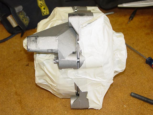
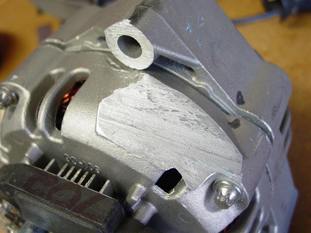
First things first -- Mechanically the alternator would not fit. The big mounting ear on the rear interfered with the engine block, so it had to go. First I completely blocked off all openings in the alternator with masking tape so no shavings would get into the alternator.
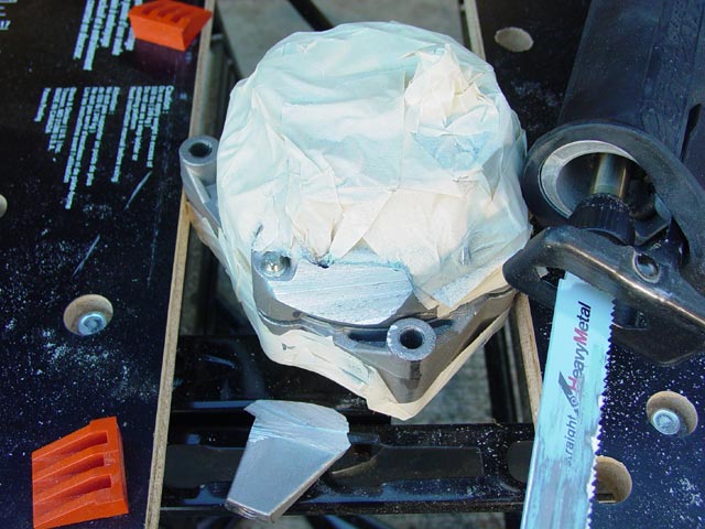
Next I lopped off the ear with a Sawzall.1
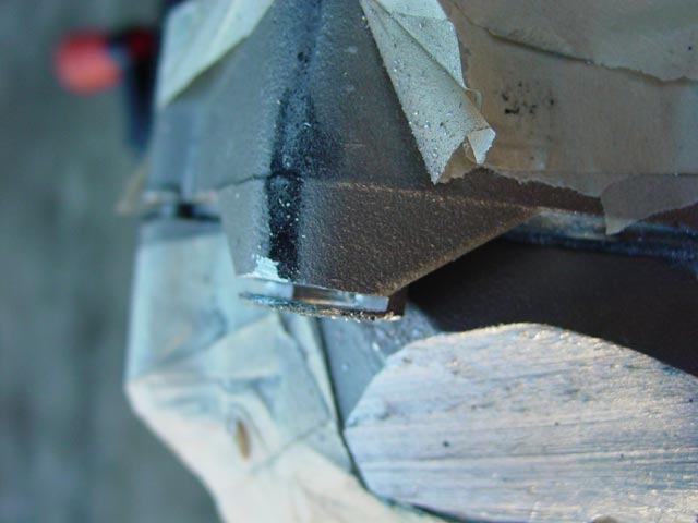
Because the pulley sat about 1/8" further forward than the centerline of the crank pulley, I cut off 1/8" from the rear of the top mounting ear.
Here it is after I cleaned up the cuts with a file and removed the masking tape.
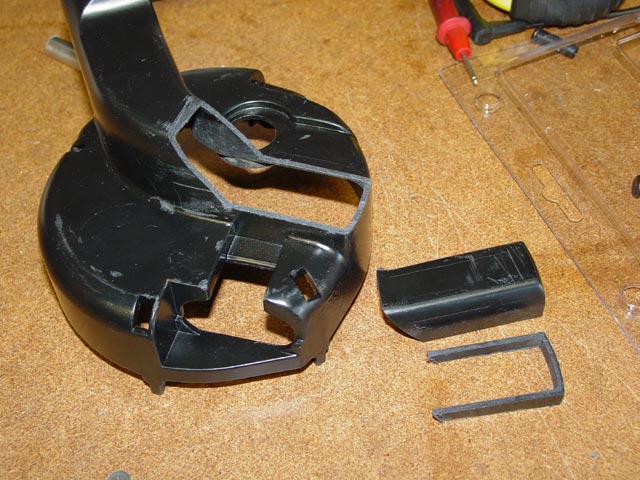
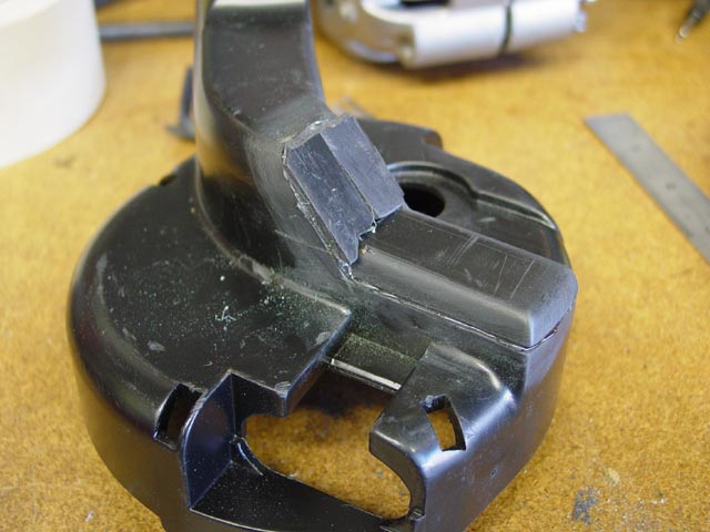
After mounting up the alternator for the first time, I discovered that I had to modify the shroud to clear the oil cooling lines, since they exit the block just behind the alternator.2 After some careful measuring and eyeballing I cut the first section out of the shroud. At first, I cut off the upper of the two loose pieces pictured at right. You can still see a thin line on the shroud itself where I made the cut. At this time I trial-fitted the alternator and found that it fit just fine. So, I estimated how much of that first piece I wanted to retain -- you can see a scribe line down the side of it. I cut it down to the desired size, then measured its height. I then cut off the lower u-shaped piece so I would arrive at the same dimensions I had on the trial-fit.
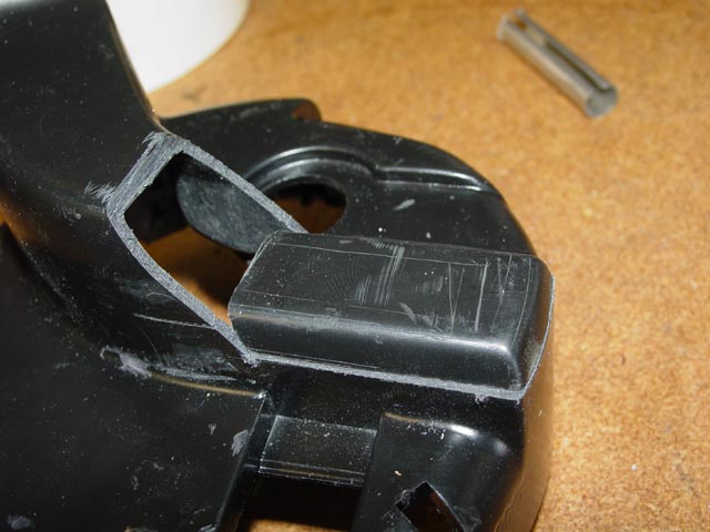
After a little trimming, this is how it fit together. Once I was happy with the fit, I stuck it in place with a thin bead of high-temp hot glue(380°F melt temp), just enough to fill the space between the parts.
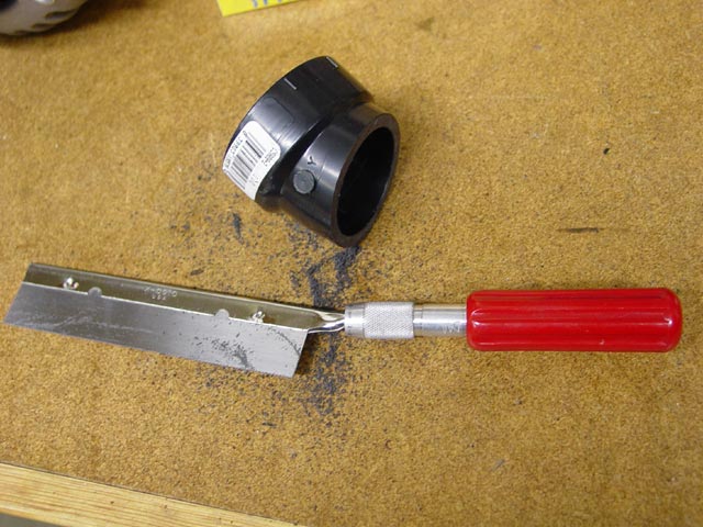
BTW, this is one of the main tools I use for precision cutting of plastic, an X-Acto razor saw. It makes incredibly clean cuts with very little kerf.
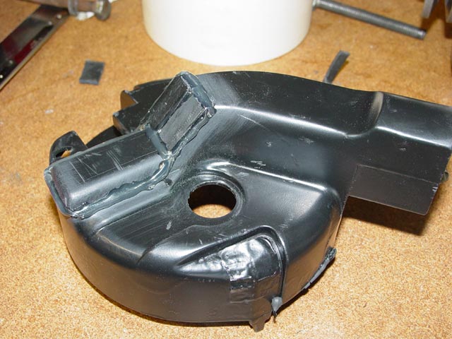
I took some leftover pieces of shroud that I had cut off, and shaped them to fit over the remaining opening in the shroud. The shroud had been painted, and you can see here where I scrubbed off the paint to give the glue some clean plastic to stick to.
Once everything was in position and the hot glue was set, I went back over each seam with a thick bead to increase the surface area being glued.
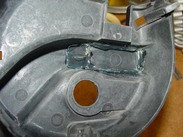
After that had set, I repeated the process on the inside.
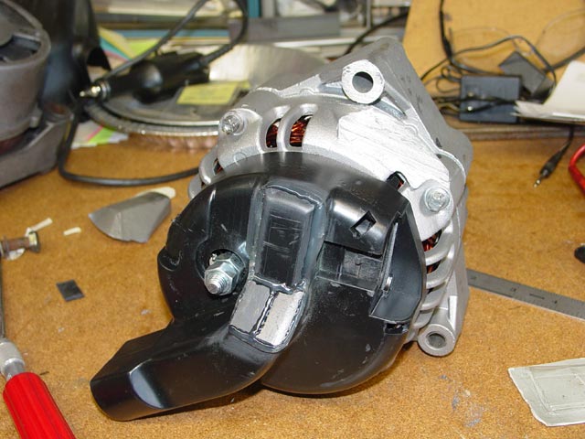
Voilá! Here is a pic of the alternator with all of the physical mods(to the alternator itself) needed to get it to mount up and swing freely through it's range of adjustment.I did need to put a pack of 4 stainless wahers -- about 5mm -- between the alternator mounting eyes and the front brackets. Some of these are visible further down the page. In the case of the upper ones, I taped the washers together with masking tape. For a permanent install I would rummage up some spacers once I knew the exact size.
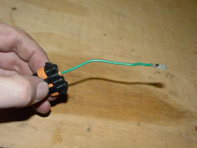
Once we settled on the right regulator type, this was the only connector needed besides the big B+ terminal. I carefully removed the other three wires and plugged the empty holes in the shell with hot glue. I did shrink wrap the terminal, BTW.

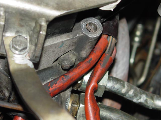
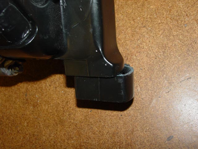
Here is the one change I had to make to the car itself. Because of the fact thatthe mounting ears are closer together than original, I had a choice... either grind down the bracket that sits on the front of the motor, or grind a relief in this easily replaceable bracket. I chose the latter.
Here it is in place. You can see what I would have had to grind off... Also, you can see that what the alternator mounts to is the engine block. This is why I cut the 1/8" off earlier... I wasn't about to cut into the block.

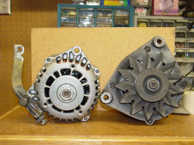
Below are some comparison pics showing the Bosch(Audi 5000) alternator alongside the Delco CS130D.
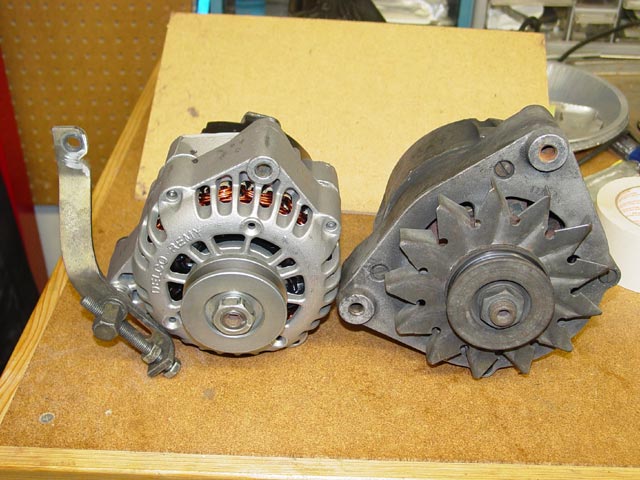
Note the smaller diameter and closer mounting ears on the Delco.
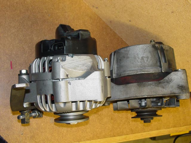
In this pic you can see how long the Delco is with the shroud, compared to the Bosch.
I had originally tried to get some ABS plumbing fittings to serve as adapters to help mate the small duct opening to the relatively large 928 alternator cooling duct. One such piece of pipe is in the pic above, with the razor saw. That was the smallest piece I could come up with, and it still brought the duct too close to the lower A-Arm to be viable. Even cutting the shroud short like you see in the pic below wasn't enough. The duct just wouldn't make the turn. What I finally settled on was some 11/2" neoprene-canvas duct that would clamp directly on the shroud, and halfway to the belly pan I would adapt up to the standard duct size with an ABS bell reducer. I had already ordered it when I found that I couldn't get the alternator to work. I still have it, and the shroud, for possible use in the future if I can get the right crank pulley(more on this later).
Here are some pics of the alternator after all mods.
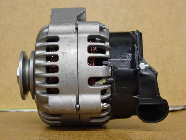
Nothing to the wiring... just the B+ terminal and the lamp terminal.
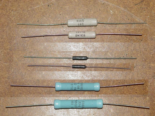
With some of the regulators that I experimented with, having a resistor in parallel with the dash lamp was very critical. Below are the three resistors I tried. The pic below is a composite of two pics. One was taken with as much text as possible visible on each resistor, then they were rotated so the rest of the text could be seen on the next pic. They are, top to bottom: 68Ω 5W, 500Ω 3W, and 560Ω 4W. The middle one certainly can withstand 3W, but because of it's small surface area it gets VERY hot! Still, I wanted to give it a try, it was the only 500Ω resistor I could get in anything close to the right rating, and the Delco regulator is supposed to work with an exciter resistor up to that value.
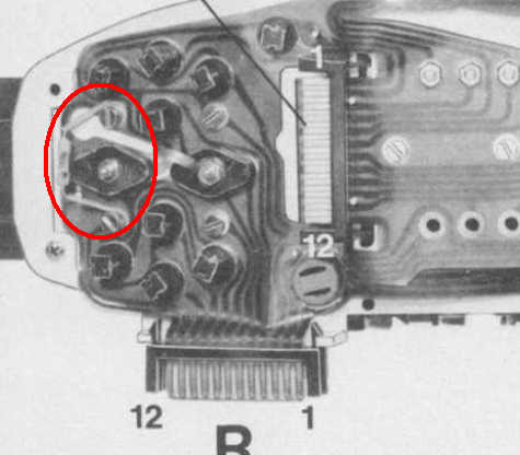
Below is a picture of the resistor that is attached to the rear of the gauge cluster on later cars, and is a recommended change for early cars when installing the later alternator..
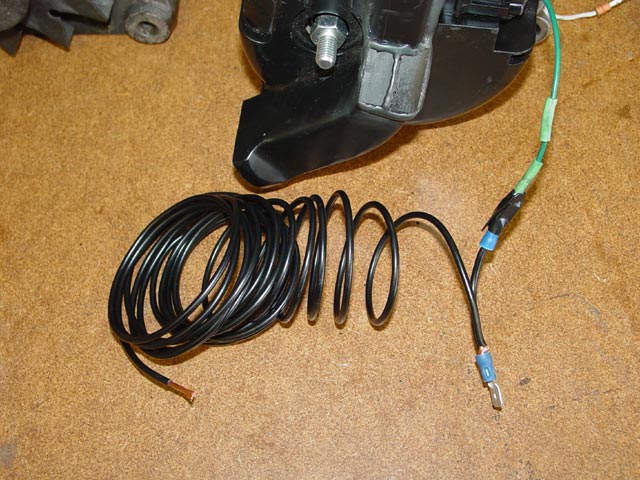
Below is the test wire that I used to test various resistors in parallel with the dash light. Simple concept, it's a short adapter that fits between the dash light wire & alternator, then the long coil of wire was routed through one resistor or another to the B+ terminal on the passenger fender.
So, once the alternator started charging, it charged like crazy. 14.5V, no matter what I turned on, the most load I could get on the system with everything turned on was ~90A. Unfortunately, once my engine RPMs dropped below about 900RPM, the alternator would not charge at all. To get ~90A out of it I needed to be turning at least 1200RPM. So... that means the rotor was turning about 2500RPM. My conclusion is that I need to get a 3:1 ratio at the spec 800RPM for this thing to work right. That means a 7.5" crank pulley, and I need to check and make sure that would clear the oil tube. If it would clear, then I can move forward with trying to find a crank pulley that will work.
Another possibility is to convert to a ribbed belt, in which case I can install a 17/8" pulley on the alternator, which would only require a 55/8" crank pulley to get me ~2500RPM on the rotor at idle.

1 If you choose to install this alternator without a shroud, using the stock rear cover, this step will not be necessary. In this case simply have the "clock position" set 90° or 180° clockwise from what is shown here.
2 If you do not have oil cooling lines exiting the block in the normal factory location, you will not need to modify the shroud. If footnote 1 applies to you the alternator will clear the cooling lines with the unducted shroud.