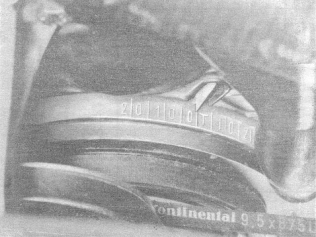
First, make sure the engine is at top dead center(TDC) for the #1 piston (front right hand side, opposite the distributor). Use a 27mm socket to turn the crank clockwise until the TDC mark lines up with the pointer as shown. CAUTION: DO NOT turn the engine counterclockwise.
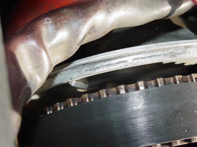
Next, make sure that the TDC marks on the cams line up with the pointers. If they are off less than one cam tooth, don't worry about it for now. If you cannot see the marks on the cams, turn the crank 360° and check again. This is the 1-4 cam
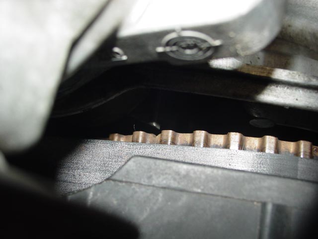
Here is the 5-8 cam. If the marks are off more than one tooth from the pointers you will have to correct this by re-threading the cam belt.
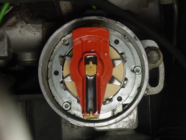
Assuming you were able to line up the crank and cam indicators, remove the distributor cap and verify that the rotor is pointing to the mark on the lip of the distributor housing. If it is not, you will have to remove the distributor and orient the rotor in the proper position.
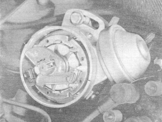
The pic below shows how my own distributor is clocked. It's easier(compared to the pic above) to make out that the rotor is pointing pretty much straight forward, perpendicular to the cam belt cover. Note also that the ignition is a few degrees past the trigger point(clockwise rotation). Measuring off of the image I come up with ~7.5°. Since the timing is normally advanced about 8° at idle and the crank is at TDC here, this pic may be used as a reference to set initial timing for startup after distributor R&R.
I believe the WSM says that for an initial setting upon assembly, position the distributor so that the hold-down bolt is in the center of the slot. I have used this approach and the engine will fire but it will be much too far advanced. Most distributors I see are off to the side as in the WSM pic above and my pic below. Just make sure you line up the rotor and the mark, set the pickup just past the trigger point, ensure you have plenty of room to adjust the distributor in either direction and it will be close enough to run.
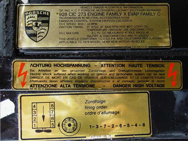
If you had to reposition the distributor shaft in the above step then you will probably have to move the plug wires around on the distributor. The rotor should be pointing to the #1 plug on the distributor, start by plugging that wire in then follow the firing order as shown on the engine bay sticker below. Note that with OEM parts the wires and the distributor cap are marked with cylinder numbers -- there should be no reason to connect things any way other than by following these markings.
Now, on to the WSM testing procedure.
Testing Prerequisites:
Battery fully charged, fuel in tank, engine or ambient temperature between 0°C - 40°C(32°F - 104°F). Temperature has considerable influence on test values.
Note that dangerous voltage is present on ignition secondary components, such as the coil, cap, rotor, wires, and plugs. Take precautions to avoid electrocution.
Symptoms:
Starter turns, engine will not start or does not develop sufficient power.
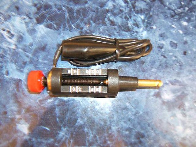
Test 1: Test for sufficient spark.
Connect spark gap tester(example below) to ignition coil terminal 4(secondary output) and set gap to 12mm. Crank engine.
Spark present across 12mm gap??
No: Go to Test 7.
Yes: Check Secondary Ignition System.

Test 2: Check Distributor Cap, Rotor, ignition cables and spark plugs.
Resistance of ignition lines including plugs should be 2.5KΩ.
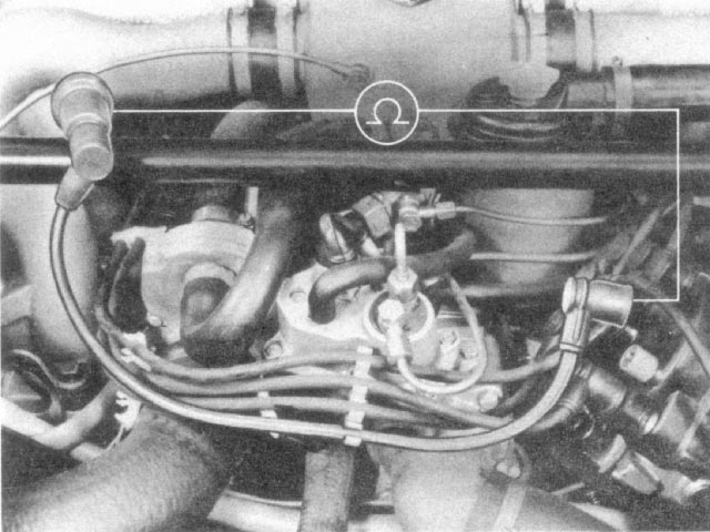
Resistance of rotor should be 5KΩ.
Correct any issues found in above tests.
Spark at spark plug?
No: Repair secondary side.
Yes: Check Ignition Timing.
Test 3: Check Ignition Timing.
Timing Correct?
No: Adjust Timing.
Yes: Check Fuel System.
Test 4: Check Fuel System
Engine receiving sufficient fuel?
No: Repair fuel system.
Yes: Check Resistors and ignition coil.
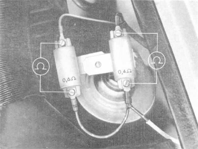
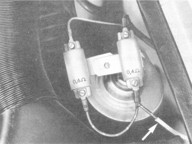
Test 5: Check Resistors and ignition coil.
Check ballast resistors:
- 0.4Ω Resistor: 0.35Ω - 0.45Ω
- 0.6Ω Resistor: 0.55Ω - 0.65Ω
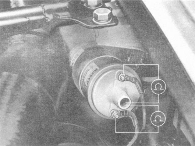
Check coil Primary and Secondary:
- Primary(terminals 1 and 15): 0.33Ω - 0.46Ω
- Secondary(terminals 1 and 4): 7KΩ - 12KΩ
Resistance values correct?
No: Replace resistor(s) or ignition coil.
Yes: Measure voltage of ignition coil.
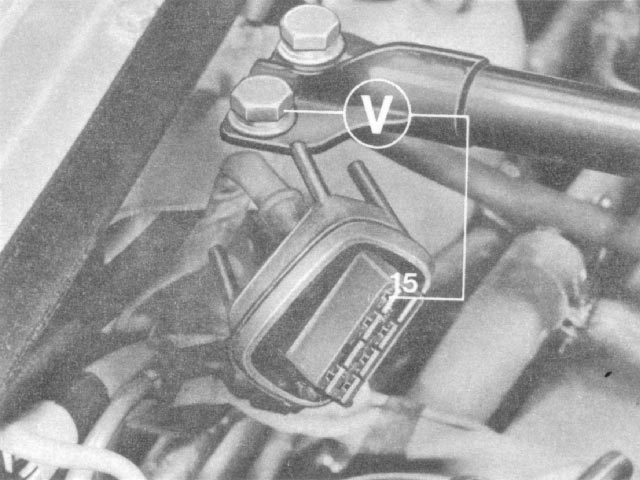
Test 6: Measure voltage of ignition coil.
Turn on ignition. Voltage at terminal 15 should be at least 3V.
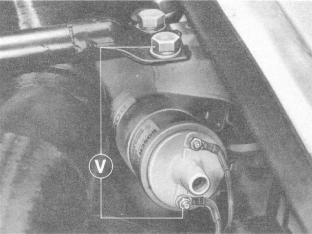
Battery voltage while performing above test must be minimum 11V.
Voltage values correct?
No: Check voltage drop at wires and connections on ignition switch, resistors, ignition coil and control unit, and eliminate voltage drop(also check coil ground).
Yes: Go to Test 11.
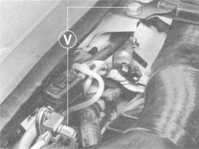
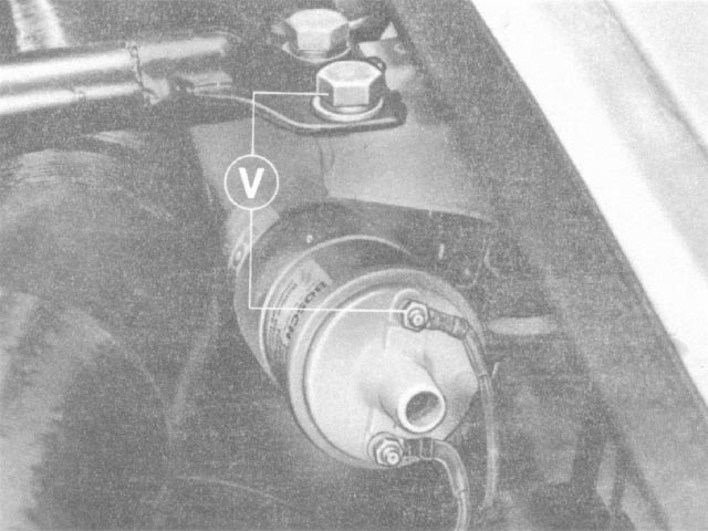
Test 7: Check starting voltage.
Disconnect line leading to starter terminal 15a at 0.4Ω resistor and connect voltmeter. Measured voltage must be the same as battery voltage.
Starting voltage good??
No: Eliminate break in supply line or contact 15a in starter relay.
Yes: Measure sensor resistance.
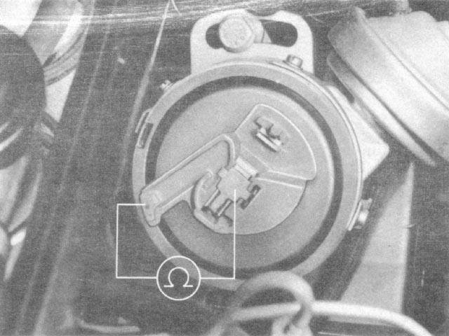
Test 8: Measure sensor resistance.
Measure sensor resistance including sensor line at disconnected ignition control unit plug between terminals 7 and 31d.
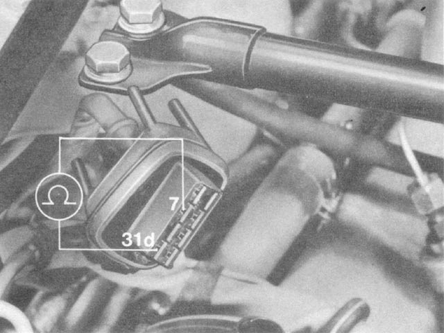
Measured value between 485Ω and 700Ω?
No: Pull off sensor line (green wire) from distributor and repeat above test. Resistance between 485Ω and 700Ω?
- No: Replace distributor
- Yes: Replace sensor line(green wire)
Test 9: Check for short to ground.
Check sensor coil with sensor line(green wire) for ground between terminal 7 and ground or between terminal 31d and ground. Infinite resistance to ground?
No: Pull off sensor line (green wire) from distributor and repeat test on sensor. Infinite resistance to ground?
- No: Replace distributor
- Yes: Replace sensor line(green wire)
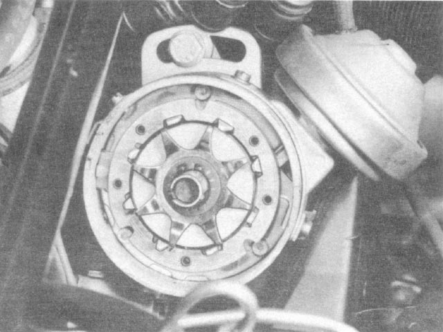
Test 10: Check for mechanical damage to sensor.
Check sensor system for mechanical damage. Visual inspection: gap between rotor and stator?
Sensor system good?
No: Replace distributor.
Yes: Go to Test 5.
Test 11: Check ICU voltage.
With ignition in "Run" position, check voltage at ignition control unit plug terminal 15 against ground. Voltage must be same as battery voltage.
Voltage correct?
No: Check voltage drop in line from ignition switch to control unit, and eliminate voltage drop.
Yes: Check voltage at coil.
Test 12: Check voltage at coil.
With ignition in "Run" position, check voltage at ignition coil terminal 1 against ground. Voltage must be max. 2V.
Voltage correct?
No: Replace control unit.
Yes: Check Dwell angle.
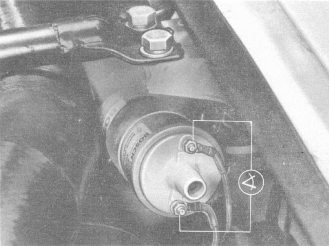
Test 13: Check dwell angle(short test on warm engine). Usually the green lead on dwell meter goess to coil - and the black lead goes to chassis ground. Don't hook it up across both terminals as the pic below seems to imply.
Dwell angle:
- 25° - 39° at 1500 ±50 RPM
- 33° - 40° at 5000 ±50 RPM
Dwell angle correct?
No: Perform Test 8, Test 9, and Test 10. Replace Control unit if sensor is good.
Yes: Engine must start and/or engine power must be adequate. If not, there is a mechanical defect.
Test 14: Ignition Failure.
Disconnect tachometer(12-pin plug on instrument cluster, right, or plug G on CE panel).
Ignition failure eliminated?
No: Replace control unit.
Yes: Replace tachometer.