With the smaller garage came a need to make better use of the space that was available. The utility room was a disaster. One thing that I needed was a garage sink, and the laundry room had been built with 1957 wash equipment in mind. It had the plumbing at one side of the room, and the Bosch frontloaders barely had room to swing the doors open without brushing the wall on the other side of the room. In order to set them at the end of the room I was going to have to move water and power, and there was a bigger problem -- the foundation.
At some point in the past, someone had chipped away at the foundation to get a washer and dryer to sit across the narrow end of the room, but they had not chipped enough away for these machines to fit. I ended up building a wood platform to provide a wide enough base. That's visible lower down on this page. There wasn't much to it, just three 2x6s with some cross-braces, some plywood, and some equipment feet with threaded inserts that fit holes drilled in the wood so that I could level it on the uneven floor.
As I mentioned on the previous page, insulation was a top priority. What I ended up using was a radiant barrier R15 Al-Foam-Al composite, stapled to the ceiling joists with a ~1.5" air gap. The garage door is already comprised of two layers of sheet metal with a ~1" air gap, so it turned out that it didn't need any insulation. Over the summer of 2008 these small changes proved to be a huge benefit. Now, with the doors closed and the fan running, the garage stays around 75° on a 100° day.

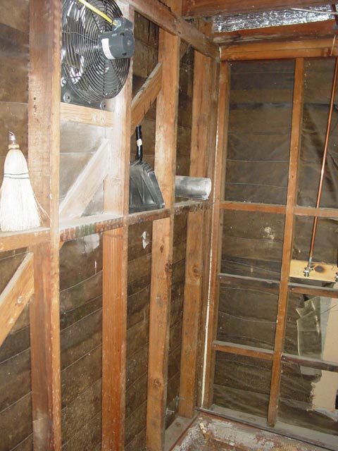
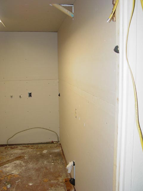
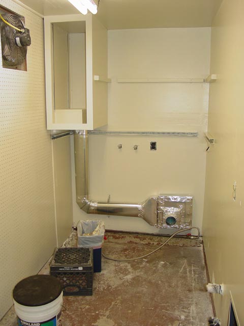
Here are the beginnings of my work on the utility room. I wanted a ventilation system so that I could run the car, weld, use noxious chemicals etc. without having to open the garage door more than a couple inches either on cold nights or when the sun is beating in the doorway. At this stage I had built the platform to work around the foundation and knocked out the pegboard in the area where I wanted the fan, cut through the stucco siding and installed the fan on some stringers anchored to the redwood studs. As a side note, the dryer exhaust was penetrating the wall in what was, IMHO a very bad spot but it could not be moved closer to the utility room rear wall because there was a drainpipe in the way on the outside, as well as a load-bearing doubled-up stud in the corner that could not be cut. I'll get to my creative solution to that in a bit, I just wanted to point out how crappy it was to begin with.
 Also, there was a fair amount of shelf space but the shelves were weak and would not hold much weight.
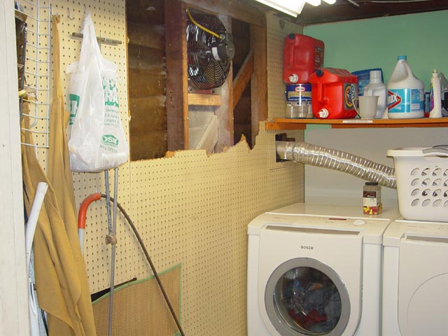
Here are the outside louvers which do a pretty decent job of keeping the weather out when the fan is not running. There is a very slight draft through here in the winter but never enough to make the room uncomfortably cold and never any water.

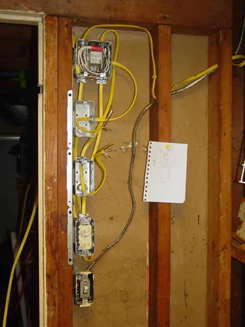
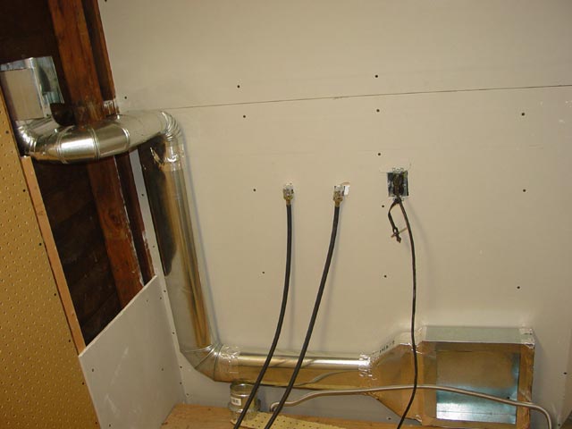
I set up the exhaust fan so that it could be switched on at a low speed governed by the speed control, or the adjacent switch would override the speed control for full speed. Also there is a thermostat which kicks the fan to full speed when the temperature gets too hot. I usually leave it set to 85°. At the top is a relay that allows for the manual or thermostat override. The pic below shows an intermediate stage, ready for drywall.
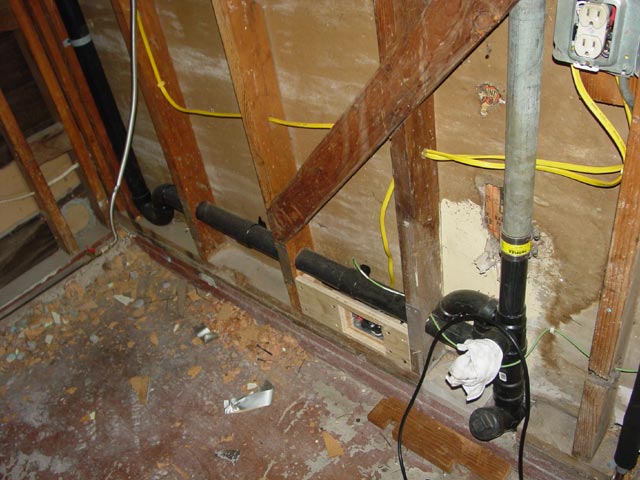
Here is a look at the original plumbing. The washer drain is routed through a standpipe that I added to what was originally a cleanout. I did this when I discovered that the tee that connects the original standpipe(the open ABS pipe just beyond the one that is in use) between the roof vent and the sewer was completely corroded out. I could grab the tee and shift it 1/4" or more out of line because the nipple between the tee and the cleanout was corroded through! At this point I had removed the wallboard around the plumbing to see what I had to deal with. All of the wallboard in this room was crumbling fiberboard, which is a fire hazard so I planned to rip it all out and replace with gypsum.

I didn't get detailed pics of all of the intervening steps, but at the point where the below picture was taken I had stripped the rest of the wallboard, repaired the drain line, added shutoffs for the water supply lines, routed the water supply lines and a drain to the back wall of the room, stubbed out the drain for the sink, relocated the anti-hammer plenums, re-routed the 220V 30A outlet(above pic, far left) to a sub-panel via a recessed junction box, added a 1"x6" support plate for the support strut on the sink to attach to, and run a dedicated circuit to the kitchen counter(back side of this wall) to run the toaster and microwave. This circuit had been wired to far too many outlets and overhead fixtures on the front of the house and it was necessary to take these high-load items out of the circuit.

The junction box sitting under the drain here originally went straight up to the 220V outlet mentioned above, and it also contained a 110V circuit for the plug on this wall. I had to replace the wire on the 110 circuit and I spliced some 10/4 Romex from this location to the load panel that I added. That Romex runs up the stud just left of the drain vent and is not visible in this pic. Drilling the holes in the studs and roof joists for these wire and pipe runs was no picnic. Try drilling 50 year-old redwood next time you want to entertain yourself! The conduit for the 220V circuit came through the foundation and could not be moved closer to the wall; I had to make up the plywood contraption that you see in the pic below to anchor the junction box and to recess the coverplate into the wall.
Here is a closer look at the junction box before I finished sanding/filing it to a nice shape and filling with wood putty as needed. The orange 10/4 Romex for the load panel is visible in this pic.

This pic shows the two new dedicated circuits that I added(Yellow Romex) for the microwave/toaster in the kitchen and the washer/dryer. The water supply lines are reversed with hot on the right, but it was far simpler to do that and mark the spigots clearly than to try to cross the pipes.

In this pic you can see a bit of where the foundation was chipped out at the lower right, and you can see an edge of the radiant barrier insulation that I put above the ceiling in this room. It's all ready for the next step...
Here I had finished the pegboard on the north wall and roughed in the drywall. I actually went a bit too far around the dryer exhaust, as you will see in a moment...

More drywall...

In this pic you can see the bit of patching in that remains to be done around the sink drain/cleanout and the roof vent. You can also see some of the wires for the rest of the garage circuits dangling from near the load panel, waiting to be hooked up.
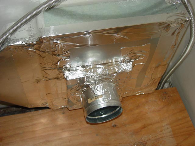
The dryer exhaust was penetrating the wall right where I wanted a cabinet, so I had to remove a small section of the drywall that I had just installed so that I could route the duct inside the wall. I used oval pipe to maximize the use of space. In a room this tiny, every inch counts! All joints are attached with 4 sheetmetal screws then taped with aluminum tape.
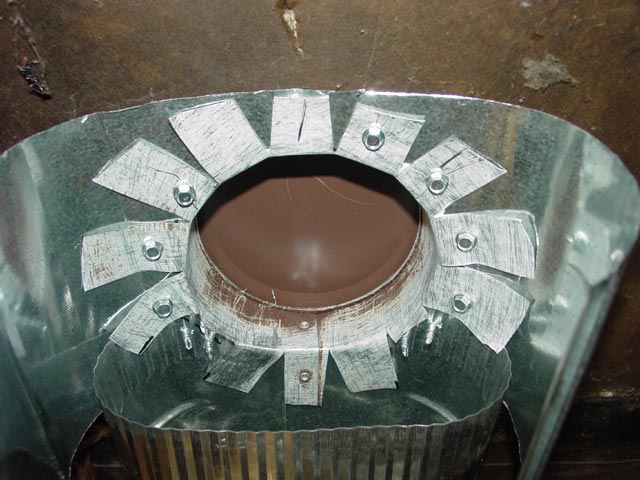
Attaching the ductwork to the exhaust shroud on the outside proved to be a bit of a challenge. I cut and split the outlet and splayed out the cut ends, screwing them to a split-open section of oval duct. This resulted in the shroud being pulled up very tight against the outside wall. I filled the gap between the shroud and the wall with a LOT of silicone then wiped off the excess once the shroud was drawn up tight.
Next I used aluminum tape to seal up potential leaks...

Then cut a custom cap to cover the end of the duct, screwing and taping it in place...
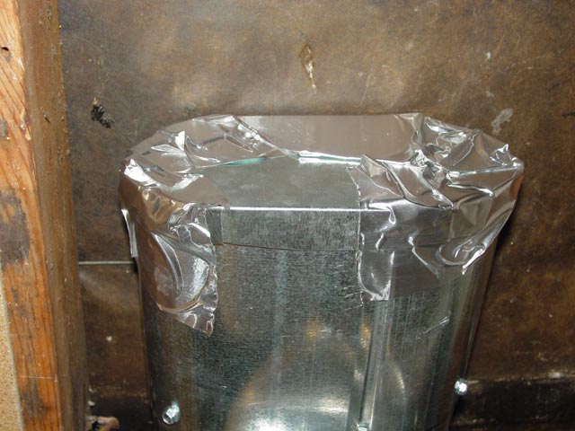
...followed by some plumber's tape to anchor it. The whole thing ended up being incredibly rigid at this point.

I set up this plenum with the intent that the cover plate could be modified or replaced in the event a different dryer with a different outlet location was installed in the future. No attachment hardware is needed, the dryer slides straight back and engages with this coupling. The plenum is anchored to the studs behind the wall with 3 2"' wood screws(some are visible in an earlier pic).

Once I was satisfied with the fit I sealed up the plenum with aluminum tape.
The next step was to build and install the cabinet. Note how one corner of the cabinet was cut out and boxed up to clear the duct. Next I installed cleats to hold the shelves, and installed an access door over the water shutoffs. I also finished the drywall, taping the joints and filling the screw holes, and when finished I gave the whole room a couple coats of paint.
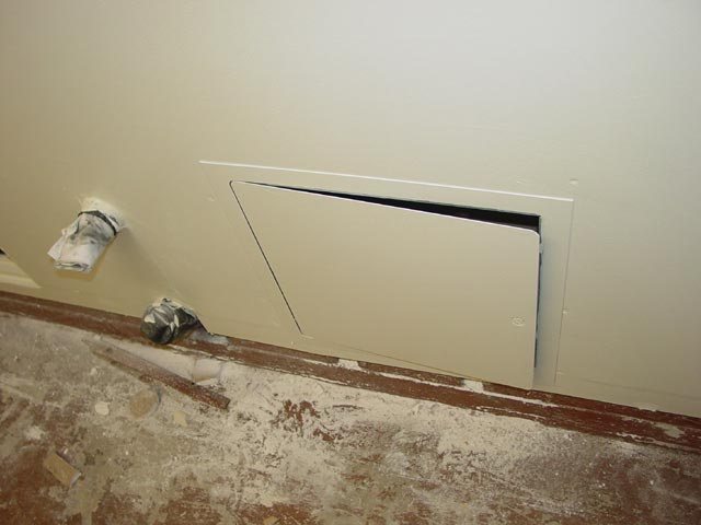
This is the access door for the water shutoffs, which sits under the sink.

Here is the completed project. You can see how the wooden platform provides a solid base above the foundation. The shelves are not anchored and may be slid out to access the water supply, drain, and power. The box feature inside of the cabinet worked out to be a perfect place for the detergent. The sink is fully installed and operational in this pic. The faucet has a vacuum break, a hose thread that I've added a swivel spray/aerator unit onto for versatility, and just visible beyond the faucet is the watertight cover over the outlet that I upgraded to a GFI circuit. With the aerator removed, this faucet will fill a 5-gallon bucket in just a few seconds. This is very handy when I want to run hot water through a garden hose. The backsplash is just melamine with some plastic trim around the edges. I have already used this sink many times for rinsing parts cleaned in simple-green and washing my greasy hands after working in the garage.

A few times I have used straight ammonia or bleach(never together) for cleaning things in the sink, and this fan is just the ticket. When it's on full blast I can barely smell whatever chemical I am using. I've already put the pegboard to good use as well.

Here are the nearly-finished fan controls -- I have a plate for the relay, I just need to cut a square hole in it to clear the relay itself.

So that's about it for the utility room. This project had a number of dependencies intertwined with it. The biggest one was that I didn't have power for the garage lights and outlets until this was done, at least to the point of running the 10/4 Romex out to the new load panel. More onfo on that on the next page...