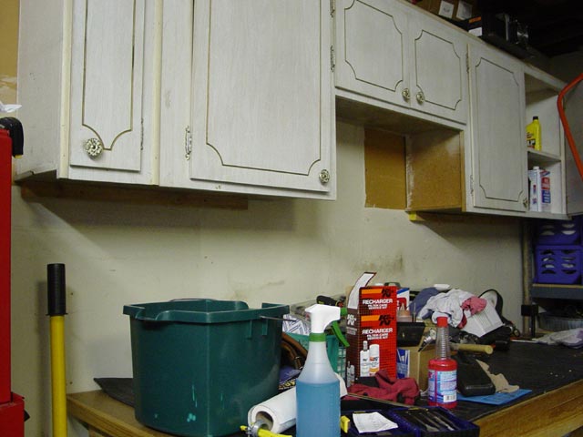
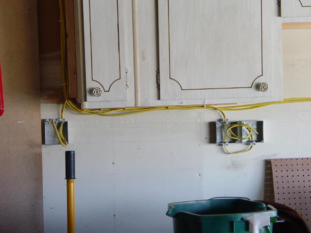
Well, it took me long enough to get to it, but finally I started paying attention to the garage around June. When the owner of the house had the kitchen cabinets re-done, he put the old ones up in the garage. I can see why they had to go... Anyway, I had to move them to the right at least four inches to make the room I needed to set up my toolbox and parts shelf the way I wanted. I went ahead and moved the cabinets as far down the wall(to the right) as they would go, given the fact that there is a gas main that runs up the wall. The edge of the cabinet is up against the pipe at the right of the pic.
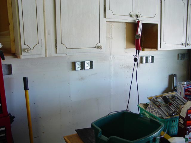
So of course, the first thing you need in a workshop is power. I decided to pull 4 20A circuits, one for some overhead lights, and each of the three others feeding two fourplex outlets. Here, I have just aligned the outlet boxes along a level line drawn on the wall.
At the last minute, I decided to mount the leftmost box which would house my light switches a bit higher than the others, so that my jack handle wouldn't bump into it...
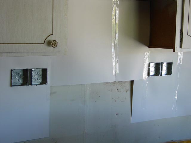
I used some posterboard that was laying around to create the template that I would use to cut the pegboard to fit around the cabinets and outlets. It's easy -- just take one piece at a time, cut it to fit, tape it to the other pieces, start another one...
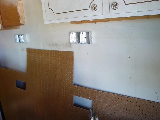
Then I marked and cut the pegboard according to the template. You can also see the 2x2 cleats around the edges that the pegboard will be screwed onto.
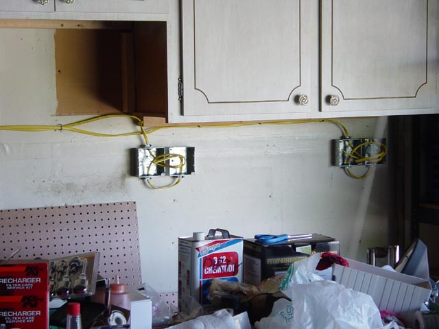
I ran four runs of Romex, 12/3. Code called for one staple per wire per 4 feet, I used one per 2 feet. The wire was run to each box, then short stubs added to join the boxes. All points where cable penetrated boxes used clamp-type feedthroughs. If I were starting from scratch in a house I owned, I would use deeper junction boxes attached to the studs behind the drywall. The extra depth would have allowed me to use simple couplers between the boxes, saving considerable labor. As it was, things were tight. Also, I could have mounted the pegboard to 2x4 cleats instead of 2x2 to give more mounting depth, but I traded labor for a little more room.
Here are the rest of the wires. All staples went into the wood cleats or into wall studs.
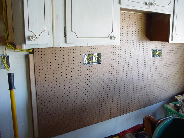
With the wires run, I was able to hang the first section of pegboard. There is a 2x2 cleat along the bottom, and a 2x4 at the left where I will add another sheet of pegboard. It was marked and cut using the same posterboard template method as with the first piece.
I mounted a 2x4 to the wall to help support the cord reel. Once the pegboard was all screwed in, I put the outlets and outlet covers in place.
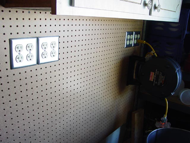
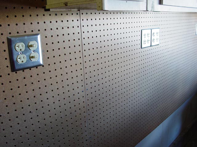
Here are the other outlets and the light switches. Also visible here, I extended the pegboard all the way to the garage side door.
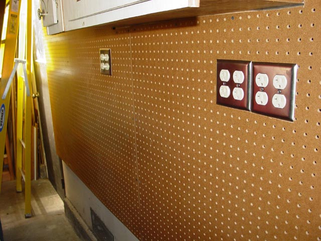
Another look at the light switch. I decided on one switch for each 8-ft fixture, because I might not always need them both on, and why waste the power? Also, these two outlets next to the switches are on the same circuit as the lights, and are intended to be used for whatever chargers, etc. I might need for stuff in/on the tool box.
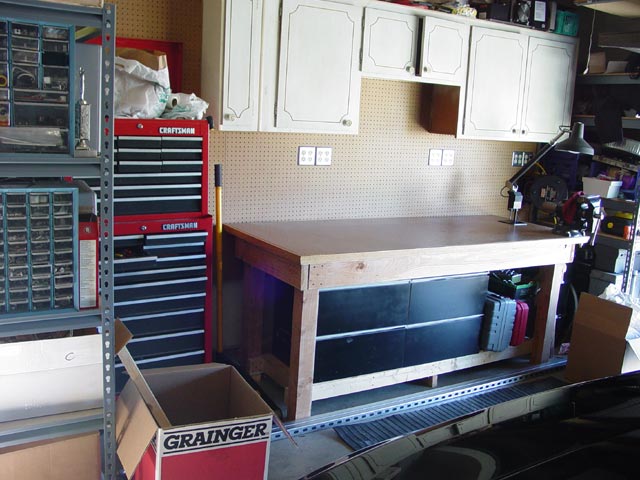
So here's how it turned out, with most of the big stuff pushed into place.
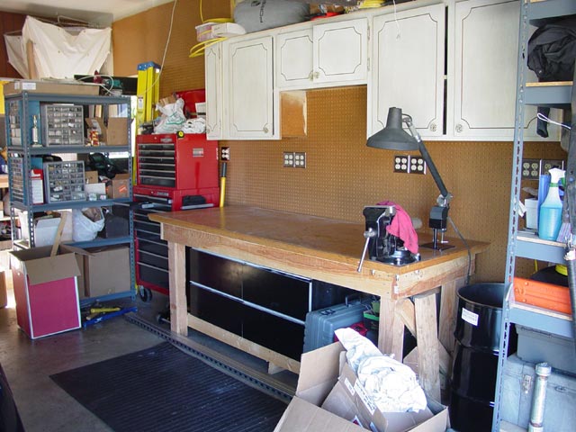
Another angle, which shows how the pegboard goes clear out over the side door. The shelf is not yet pushed back in against the wall. The loop of yellow wire on the top left of the cabinet is the loop from the light switch, which will be run out to the center of the garage ceiling in the next installment. Stay tuned...

For now though... time for a beer!

BTW... I can't remember the last time my bench was so clean. Good thing I took a pic...
