As I tried to repair this connector I asked a few experts on the 911 and racing sites. I also asked PCA Porsche Tech Guru Alan Caldwell for his thoughts. He replied:
"Hi Dave, I think the wiring diagrams are a little confusing on the 911SC CD and distributor wiring. As far as I know, all the SCs had the same wiring, yet the diagrams are not quite the same. The 1978 diagram shows two separate wires coming out of the distributor and going to a connector, T2E, and the wire colors are brown and green. Then it also shows two separate wires continuing from the connector to the CD; a shielded wire that goes from the brown wire coming into the connector to the 31d terminal on the CD (31d is a universal ground) and a continuing green wire from the connector to the terminal 7 on the CD. The reason this diagram struck me as being strange was that the model tech intro book for 1978 has a discussion and picture of the SC distributor and shows just a single cable (I assume both wires are inside) with connectors on each end and the parts catalog shows just one cable with connectors on each end. If you look at the 1982 diagram (which is the last SC diagram in the factory manual), it shows that both the cable from the distributor to the connector and the second cable from the connector to CD are shielded and that the shielding is, in fact, the ground circuit leg of the connection and is connected to 31d on the CD. In other words, the shielding is the ground connection from terminal 31d on the CD to the brown wire connection on the distributor. I can't remember on my 1978 car whether there were two wires or just one going from the connector to the CD, but my guess is that it was just one because I seem to remember an integrated plug with all 6 wires plugged into the CD. So my conclusion to all this is that the shielding on that circuit is nothing more than the ground portion of the sensor circuit between terminal 31d on the CD (which is a universal ground) and the sensor circuit in the distributor. It definitely needs to be a good connection or the sensor won't work.
...
Hi Dave, Just a short follow up on your question regarding the 1983 911SC distributor Hall effect sensor wiring. I asked Chris Powell about the connecting wire to the CD box and Chris says that it appears to be a single cable, but has the shielding under the insulation so there are two contacts at each end of the cable in the connectors, one for the shield and one for the conductor (he had one in his shop). This would agree very closely with the way the 1982 wiring diagram is drawn. Even though I had my 911SC for 20 years and worked a lot on the engine tune-ups and wiring and remembered the wire coming out of the distributor as being a single cable, I sure couldn't remember what the wire was like from the connector to the CD box. Both the 1978 and 1982 diagrams show the cable shielding attached to the 31d terminal on the CD box which is the universal ground. Allan Caldwell "
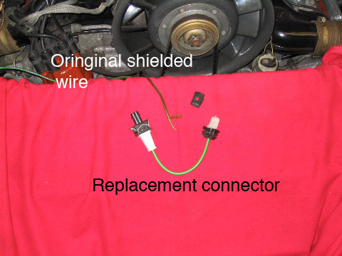
Roll over the picture to see a closeup of the new connector (930.602.907.01).