|
The Maintenance Files |
|
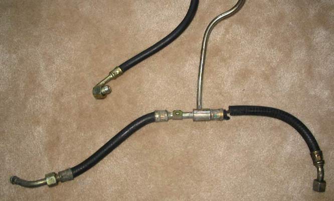
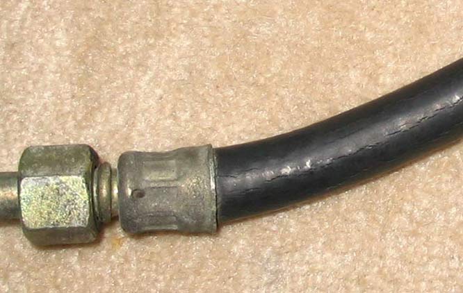
The 'notorious' 3.2 Engine Fuel Line
had been in my sights for a while. If you don't know what I'm
talking about & you own a Carrera, go out to your garage now!
Inspect the rubber lines that come off the rear of the fuel rails on
both sides. Do they look like this below? See all of the cracks? |
|
|
|
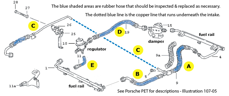
Here is where it all is:
|
|
930 110 411 03 (19) hose from fuel regulator to damper - labeled D 930 110 509 01 (11) small line off the bottom of the regulator - labeled E You have 3 options for replacement:
I will concentrate on Option #3 - the DIY approach with new braided lines. I opted for this method because it was an easier DIY since an engine drop is not required & even the intake can be left in place. I will admit however, that I didn't do the E line. It & the D line on my car looked brand new so I left them until a later date. I have the parts here waiting. I should briefly touch on the safety issue that some raise about AN fittings. AN fittings & hose are widely used in racing cars & industrially for many, many uses. While probably not recommended for very high pressure use, they are easy to install, easy to uninstall & safe for standard fuel & oil lines etc. ******************************* ********** DISCLAIMER ********** ******************************* Gas burns. All it needs is ignition & oxygen. Think of your 911 engine as one big Zippo. If you do not have confidence in the quality or use of twist-on connectors for fuel, or the assembly of same, then this is not something that you should attempt. Although they are used extensively in many, many applications of fluid transfer, the success of their usage is totally dependent on the quality of the terminations. If you decide to ignore this disclaimer and recklessly throw caution to the wind and use these fittings as a fuel line on your car, the risk is all yours. Just outfit the family in properly sized Nomex suits, and you should be good to go.
Sourcing: The 16mm fittings are European & are available from: http://www.batinc.net/porsche.htm Look in the Porsche oil cooling pdf on the site - starting on page 16. The standard -6AN fittings & hose I sourced from: http://store.summitracing.com/ Search on Fittings & Hoses
|
|
|
|
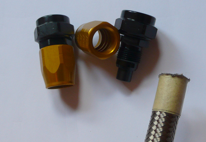
Hose A: 12 ¼" with 16mm straight
to -6AN on one end & -6AN on the other These measurements should be accurate (posted by Jerry Brinkley http://forums.pelicanparts.com/showthread.php?s=&threadid=238230 & I used them) but you are wise to measure your own existing hoses before you cut & terminate. I didn't write down a step-by-step how-to but I followed Eric Coffey's excellent directions found http://forums.pelicanparts.com/showthread.php?s=&threadid=80621 Have an assortment of 10mm sockets - long & short - with extensions & 10mm wrenches, as well as 17mm, 19mm, 22mm & different sizes of adjustables. Are you getting scared, yet? Taking everything apart & accessing some of the fittings will try your patience & skin your knuckles. Do I mention that it's a serious PITA? It is also wise to have some mirrors available & even one of those fancy mirrors on a stick, so you might be able to see what you are doing. The Reader's Digest version: 1. Disconnect the battery & have a
fire extinguisher charged & ready. Gas burns. At this point, you are ready to remove the main fuel line. Other than the fuel rail & fuel filter connections, it is held by a bolt in the front & a support bracket in the rear. There is also a plastic bracket that includes a wiring harness (my memory is dim & this might be for the damper to regulator line). These last two will require inventive solutions. I dremeled the plastic bracket since I wasn't going to reuse it. The other support bracket has an Allen bolt that is rear accessible, so a mirror is your friend here.. When all was said & done, I also cut the fuel line with a small hacksaw blade to ease removal because it appears impossible to remove it as one unit. Once the old fuel line is out, it is a reasonably simple matter to bolt on the new one. I pre-assembled the line with ends, pull-tested it to ensure good connections & then 'snaked' it under the intake. The damper to regulator line requires the 16mm + adaptor at the regulator end to make it fit due to the lack of room (as per Jerry's post linked above). My line was new looking so I left it in place. Ditto the smaller line off the bottom of the regulator. This small line is the Waterloo of this job, since you have to inspect & replace it without being able to see it. I inspected it via a mirror & it looked new so I left it alone. I will replace it anyway when I do my 1st engine drop. Your results may vary . . . Re-assemble all of the engine components - MAF, heater etc - and with fire extinguisher nearby, start the engine & inspect very carefully for leaks. My installation was perfect & leak free & remains so two years later. It has been added to my occasional inspection list - but then a fuel line deserves to be inspected regularly - along with CV bolts, ER bushings, brake pads etc etc etc . . . Some pictures: |
|
Assembly of the new line was a pleasure - mainly because you can do it on the kitchen table rather than hanging awkwardly over your motor.. I cut the line to size with a Dremel & the connectors solidly lock on nicely.
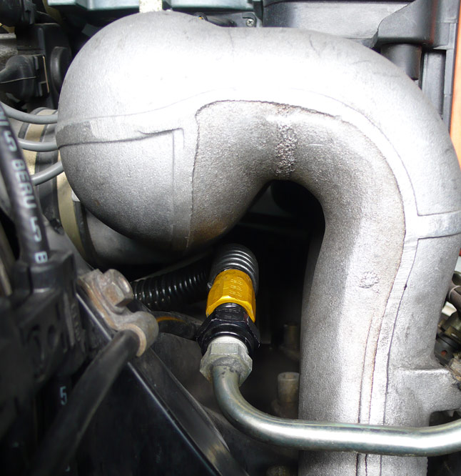
The passenger side fuel rail |
|
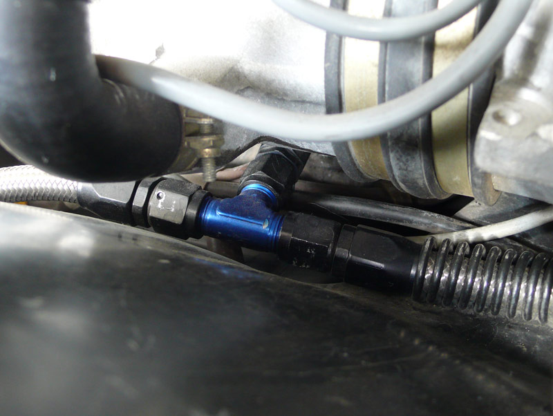
The Tee - center of engine.
|
|
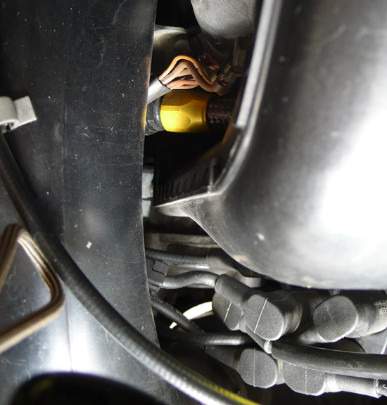
After re-assembly of the MAF etc, I fired it up & checked for leaks. None. A job well done! The driver's side - looking down. |
|
|
|
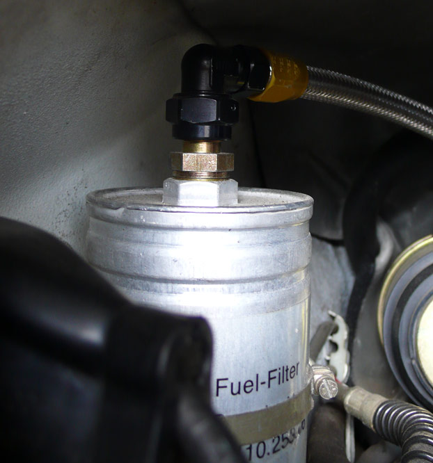
The fuel filter connection. |
|
|
|
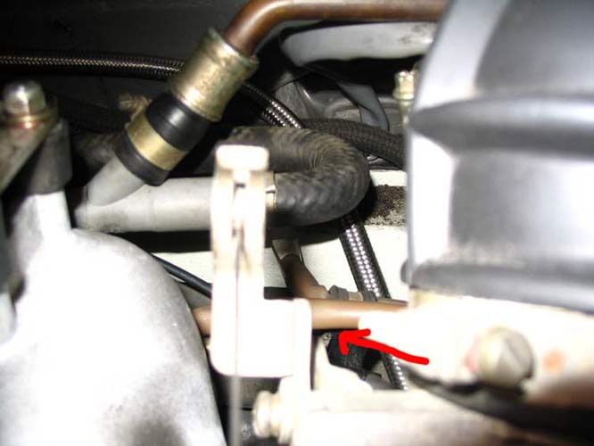
The red arrow below is pointing at the POS middle bracket with the
back-side Allen bolt. |
|
|