I don't have pics of the details for the early steps in the removal of the control unit, so I assume you can manage that yourself.
Basically you pop off the black trim piece from the unit, and then undo the 4 screws holding it into the dash, then pull the unit out and disconnect the wires in back.
Once you have the unit itself out you have to go the pita process of popping the black protective cover off the back of the unit - there are a bunch of little tabs built into the clear cover of the unit that are holding the black cover on the back. I found the easiest way to get this off was to use the notches in the black cover to pry it over the clear plastic clips on the sides, and then jam a screw driver in there to keep the parts apart while you get the end ones open.
After that tedious project, you next have to remove the a/c and recirc/defrost buttons. Hopefully you have one of the newer units with the snap in buttons, otherwise you're pretty screwed. If they're soldered in, you have to make sure to get rid of all the solder, otherwise they won't come out. Or you can cheat like I did with my soldered in buttons, in that I used a jewlers screwdriver to pry the top parts of the buttons off without actually removing the soldered in connections of the button (you'll see what I mean in the pics).
Once you get the buttons out you have to pull the knobs off - these should just come off with a firm tug, but if not wedge something underneath them to pry them off. Be carefull to get something that won't scratch the finish of the stickers around the knobs, because it scratches easily and looks odd once scratched. You'll note that in the picture the bases of the a/c and recirc/defrost buttons are still in place in the board, this is because of my cheating and not de-soldering them all the way. Also, if your control unit looks different from this, thats fine - the newer ones with the snap-in buttons doesn't have the two extra circuit boards on the sides.
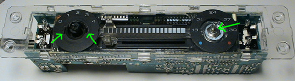
Once you get the knobs off you have to remove the nut and washed from underneath the temperature knob, and there are two clips built into the clear plastic holding the plastic in place underneath the fan speed knob. I've got the two pointed out in the picture (as well as the nut/washed on the temp knob side). I've found the easiest way to get these clips/tabs undone is to undo the temp control side first, and then use the extra working space from having that side undone to stick a flat head screwdriver under the clear plastic and carefully pop the clips off from around the fanspeed knob.
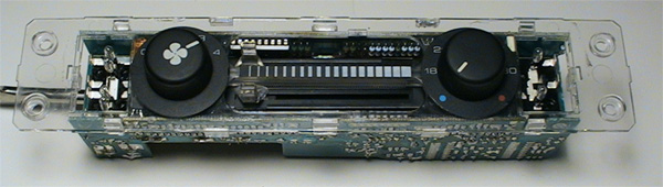
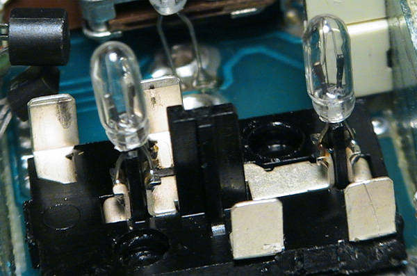
Once you have the clear cover off you can see the guts of the unit. Again, the unit in the pictures is one of the older ones with the soldered in buttons, so don't worry if yours looks different. The bulb locations are the same for both (I have a newer one in the car currently). For the buttons on both units the bulbs inside the buttons are soldered in place - there are 4 bulbs inside the defrost/recirc button and then two bulbs inside the a/c button. They are soldered in both units. After that there are two bulbs on either side of the temp control dial, which are soldered in place on the older units but are just press-in bulbs on the newer ones. Remember the pics are of the older unit, so they show them soldered in place. The other two bulbs are one inside the dial for the fan speed knob, which pulls out easily with careful use of some needle nose pliers, while the last bulb is to the upper right of the fan speed dial. It is soldered in place on the old units but is a clip-in piece on the newer ones.
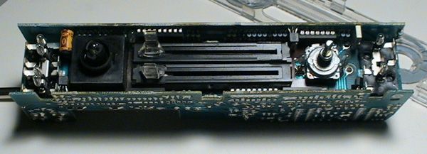
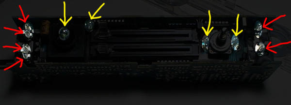
Above: picture of the unit without the clear faceplate. Below: picture of the unit with the light bulbs hilighted. Red arrows are bulbs that are soldered in place while the yellow arrows are bulbs that are clip-in ones (new style units only - the old ones have all bulbs soldered in place, except the one inside the fanspeed dial)
The following pictures are just closeups of the specific bulbs.
Note that on the pictures for the bulbs in the two buttons, the bases of the buttons are still in place on the circuit board. This is because of my cheating way of removing the button covers with popping the top half instead of desoldering the button base from the circuit board and removing the entire unit. This is only an issue on the older units - the newer ones with the pop-in buttons are extremely easy to remove/install the buttons, so its easier to work on them with them removed from the circuit board. My two cents - if you have an older style board just spend the money on ebay and buy a newer style board - MUCH easier to work with.
The 4 bulbs inside the recirculate/defrost button. They are soldered in place, but are easy to remove and replace with a soldering iron - just heat up the present solder and they pop right out, reverse the process for installing new bulbs/leds. In the pic, the bulb on the left is the top most and the right is the lower ones - each button has two bulbs: the inner bulbs are the ones that light up the face of the button (the defrost or recirculate logo on the button face) when the headlights are turned on, the outside buttons are the ones that show when the button is depressed and engaged (the yellow bar visible on the button when turned on).

The a/c button bulbs. Two bulbs, basically the same setup as the other button. In this case the top bulb (right side of picture) is the one that lights up when the button is depressed/engaged, while the lower bulb (left side of picture) is the one that lights up the snowflake logo when the headlights are turned on. Same proceedure for removing/replacing the bulbs as the other button: just heat the solder up with a soldering iron, pull the old bulb out and replace with a new one.
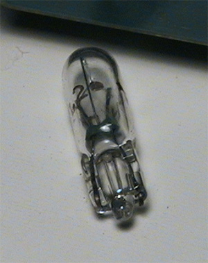
The two bulbs around the temperature dial/knob. In the older style units (pictured) the bulbs are soldered into the circuit board, while on the newer style units they are just pressed in place into some clips on the board - they pul out and push in extremely easily - first time I saw how they were held in I thought they were just spare bulbs in the panel because they didn't seem to be connected to anything. Removal is the same as the buttons for the soldered in bulbs - just heat up the solder enough to pull the current bulbs out and then replace with the new ones.


This is the bulb that is above and to the right of the fan speed knob. On the older boards its soldered in, the newer ones have it held in with the clip. When the bulb it lit up it lights the fan speed numbers and that end of the vent controls. Note that on the newer style control units the two side circuit board pieces are not present, so it is much easier to work on them. Pictures are of the old style control unit.

These last pictures are of the bulb and socket inside the fan speed control knob. I would assume you could just stick a replacement bulb in there, you just have to make sure to line up the connections for the bulb correctly without shorting it out or anything.
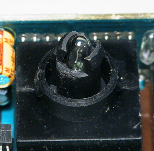
I attempted to get a picture of the connections inside the socket for the bulb in this pic, unsucessfully. You get the idea though - there are the two connections on either side that make contact with the wires on either sides of the bulb (see above pic) to get power to the bulb. If replacing the bulb with a led, you may want to find some rubber stopper or something to put below the led so as to keep the led from falling down into the socket and to keep the wires seperated from each other.
