2M 1kW Larcan amplifier
I am no longer performing 2M conversions or other Larcan repair.
If you're having trouble with your amp perhaps we can troubleshoot via email.
My email address is vo1ks at eastlink dot ca
See disclaimer below.
I've been asked about conversion of 1.5kW 6-FET low band amplifiers. This version amp can go to 50MHz by swapping out or padding about 65 capacitors throughout the board and removing several jumpers at the FET output circuit. You will need the 1.5kW 6-FET schematic diagram and parts listing. Compare values for channel 5-6 with channel 2-4 amplifiers and pad them a little more for 50MHz operation. Schematic diagrams are available elsewhere online. The 2M modification below will not work with the 1.5kW amp. The circuit board traces for each FET and the input and output splitters are fully redesigned. There is a conversion for low band 1.5kW amplifiers for 144MHz operation available elsewhere. I have not performed the modification and can not offer much assistance. Even after completing nearly 50 conversions, the 1kW amp can sometimes be tricky to make work on 2M.
Check this writeup from the UK Six Meter Group newsletter. It could be a good guide to assist with assembling your
solid state power amplifier.
Visit my
Larcan amplifier page for schematic diagrams, installation ideas, and much more.
I am building a
high power multiband VHF amplifier
around solid state 1kW Larcan amplifiers. My plan is to either parallel 4x @ 50MHz, 2x @ 144MHz and eventually a seventh 1.5kW module @ 222MHz, or 2x1.5kW @ 50MHz, 2x 1kW @ 144MHz, and 2x 1.5kW @ 222MHz.
For 144MHz I had hoped to combine the modules with the Hellenic RF Lab combiner purchased on eBay. It didn't work out quite that way.
Here are some pictures of the combiner supplied by
Hellenic RF Lab. Be wary of components supplied by this company. There are other complaints and questions regarding the seller on
eHam.net.
 These are serious commercial amplifiers, designed for 24/7 operation, not typical amateur radio equipment. Many of the hams on
Ping Jockey run Larcan amplifiers for EME and terrestrial digital modes.
The modules have been converted to 144MHz operation based on the initial work done by
Brian WA1ZMS. The procedure was further refined to produce a consistant 1kW module.
They have been modified with the serious 2M DXer in mind, ideal for today's punishing digital modes as well as SSB and CW.
Typical drive power is 20-25W input for 1kW output power. DC current requirement is roughly 40A @ 50VDC. For those interested in do-it-yourself, the details are supplied below. Power supplies can be found on eBay.
(search for "HP 253232 001" or "HP 2950")
Going price is roughly $40 or so, but with careful shopping and and some dealing you may find them for even less.
These are serious commercial amplifiers, designed for 24/7 operation, not typical amateur radio equipment. Many of the hams on
Ping Jockey run Larcan amplifiers for EME and terrestrial digital modes.
The modules have been converted to 144MHz operation based on the initial work done by
Brian WA1ZMS. The procedure was further refined to produce a consistant 1kW module.
They have been modified with the serious 2M DXer in mind, ideal for today's punishing digital modes as well as SSB and CW.
Typical drive power is 20-25W input for 1kW output power. DC current requirement is roughly 40A @ 50VDC. For those interested in do-it-yourself, the details are supplied below. Power supplies can be found on eBay.
(search for "HP 253232 001" or "HP 2950")
Going price is roughly $40 or so, but with careful shopping and and some dealing you may find them for even less.
The SSPA uses four MRF151G FETs installed on a large heatsink. It has a bias/VSWR board on the rear. The amps have breezed through a 1 hour smoke test producing a steady 1kW carrier into a dummy load. This is a considerably higher duty cycle than any typical amateur use. The time limit was caused by the IC706MK2G transmitter getting uncomfortably warm. The 222MHz version has operated for over 20 hours in a single FSK441 sked as well as many hours of JT65 EME skeds.
The amps and PSUs are very easy to set up. Treat each part as a separate block. Amplifier, relays, switching, PSU ($40 eBay item), and cooling.
Input and output connectors are usually changed out to BNC or Type-N at input and Type-N or SO239 for output.
All that remains is to connect all the pieces together, much like assembling your shack station.
The HP 3kW PSU needs three small pins soldered together, a cable for AC, and a cable for DC. These are the standard PSU used by most hams running 48v SSPAs.
Many transmitters will create a RF spike at key up despite being set for lower power output. These high power spikes can damage the FETs. The 2M amplifiers should not be driven with higher than about 25 watts. For a transmitter that produces 100W maximum output power, a 6dB pad should be used. Doing this allows a full 100W drive and eliminates any potential of spikes causing damage. For a 50W transmitter use a 3dB pad. For 50MHz amplifiers, 10W is the maximum recommended drive power. Choose the appropriate attenuator for your station.
I do not consider the attenuator to be an optional item. Given the spikes that many transmitters produce as well as the susceptibility to some FETs to overdrive damage it is an essential item! Compare the price of an attenuator vs $100+ per FET. Here is a picture of a
250W 6dB input attenuator installed on a converted 2M amplifier. With proper notice, I could install something like this on a module during conversion. Other optional items include replacement input or output connectors. 48VDC muffin fans are also available. Email to discuss ideas or requirements.
email me - [email protected]


Working NA to EU on 2 Meters
The group used a converted Larcan amplifier and mounting drawer during their TransAtlantic attempt this summer. They were heard in Europe but unfortunately nothing was received coming back. A full week of 30 seconds on, 30 seconds off took a toll on equipment, including the Larcan amp. The output jumper straps failed and started arcing. Full output power returned when the straps were soldered. Subsequent changes to this section has eliminated the weak point and no further failure has occured.
Visit the Brendan Quest website or Facebook page for details.
The low band driver amplifiers use a pair of FET. I have retuned one FET for 144MHz and improved the other for 50MHz. It creates a dual band 250W amplifier on the same heat sink. T/R switches, power supply, etc needed as per the 1kW module.
All transmitters, amplifiers, and so on will create spurious and harmonics at the RF output. These amplifiers are no different. A low pass filter or at least a second harmonic trap is highly recommended. A shorted quarter wavelength line with a Tee connector will reduce the second (and even order) harmonics considerably. The second harmonic from 50MHz is at 100MHz, right in the middle of the FM broadcast band. It is a sure way to get in trouble.
2M Conversion improvements
It's a bad idea to start conversion without a good quality capacitance meter. You should confirm parts values prior to installation. If you're unable to do this purchase 1% tolerance capacitors. Any free samples could be up to 20% tolerance and you will have great difficulty getting the amp to work. I've found 10% tolerance 100pF capacitors will vary from about 92-112pF. Low value parts will not work. 105pF seems to be about the upper limit. Pad a low value capacitor with 10pF to make it work. Even one of eight 100pF capacitors being low can prevent the amplifier from making full power. Similarly the four 150pF need to be closely matched. It seems most of the capacitors I've received measure roughly 160pF. The 100pF capacitors seem to be the most critical in terms of value. Others are more tolerant. Try to keep values of capacitors as close to desired value as possible as well as matching corresponding capacitors across the board.
James WA3LBI suggested a few improvements to Brian's original documentation. I made a few more changes to get a more reliable (and repeatable) 1kW output from the modules.
To begin, adjust bias to 500mA per side of each FET. Next, measaure the bias voltage directly on the FETs. It should be about 2.9-3.0VDC. Anything higher could indicate lower gain components and an amplifier not suitable for conversion.
On the bias board, adjust R21 for 1.5V at pin 6 of U2.
Connect to a dummy load and take measurements prior to starting. A lo/lo should produce 1kW out with 4.5W drive at 60MHz. About 8-10W will be needed for 1kW at 50MHz. Current should be roughly 38-40A. Some modules will not make 1kW at 50MHz.
Anything out of the ordinary gets rejected from the conversion line. They make good candidates for adding capacitors for 50MHz improvement and work perfectly well at that band.
Follow the Brian's instructions with additions and changes as shown in the photos below. These changes should produce 1kW right away. Do not exceed 25W drive power or 40A total amplifier current.
Take notes as you go along. Any suggestions can be added to this modification page.
I found it easier to remove all the unused capacitors to begin. (Sort them to be reused on 50MHz modules)
Relocate 24pF capacitors from C2 and C3 to C4 and C5 on the output combiner board.
Clean up the boards with solder wick. Tin the areas where the foil straps solder in place.
Install the input and output jumpers as shown in photos below.
Cut the traces for the 43nH coils at the input splitter and output combiner boards.
The original red coils can be rewound for the new 43nH coils.
C1 and C2 on the FET input boards remain in place. Do not take them off!
Note the new positions of the copper foil straps on the FET input and output boards. All straps are 1/4 inch wide.
Ca on the FET input board is relocated away from the FET.
All 68pF caps on the FET output board get replaced with 2x 33pF. Both caps for C13 move to the end of the strip line closest to the FET.
These are working pictures. Cleanup of excess solder flux and solder tidy up is needed on some of the boards shown. Click thumbnails to enlarge.
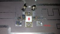
 Starting point. Unmodified lo/lo 1kW amplifier.
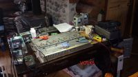 My work bench.
 Input board stripped of components showing where original trace gets cut for new 43uH inductors for L3 and L4.
Use the original red inductors and wind around a 1/8 inch drill bit. Four turns for 43nH and ten turns for 100nH.
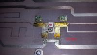
 Input board components showing new 43uH inductors for L3 and L4. Ensure C5 and C6 measured values are equal. Same for C3 and C4.
 Remove two screws holding board to heat sink. Raise the board with flat blade screwdriver. Use solder filled wick and soldering iron to clean and tin underside of the board.
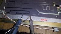
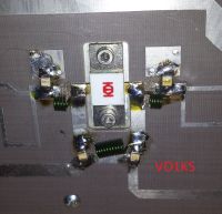
 Clean and tin copper strap. Hook it under the board and heat with the soldering iron. After cooling it should be bonded well and not come off when tugged firmly. Note position just to the left of the Larcan label.
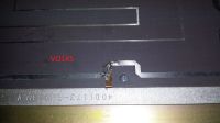
 Trim end of strap to be flush with the circuit board trace. Clean and tin both parts. Hold in place while soldering. The strap should remain flush with the circuit board.
 Completed input strap. It is positioned directly to the left of Larcan lettering.
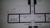 Original drawing showing position of the new PA input board stripline shorting straps. Measurement is from the outside of each piece as shown. This is different than the original document.
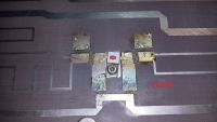
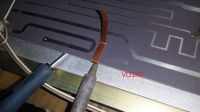
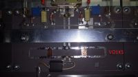 PA input board stripline sorting straps are stick-on copper foil, 1/4 inch wide x 3/8 inch long. Make sure to clean and tin the board prior to installing the straps. Notice the position of the straps as compared to the documentation.
100pF Ca mounts flush with the lower part of the wide strap coming from the FET as shown. Check the capacitor values. 95pF and below will not work. 100-105pF is ideal, but up to about 110pF will work. Try to match all eight capacitors as closely as possible. Similarly with the 150pF capacitors, try to keep them matched closely. These parts greatly affect input tuning and phase of each amplifier.
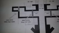 Original drawing showing position of the new PA output board stripline shorting straps. Measurement is from the outside of each piece as shown between the lines. This is different from the original document.
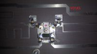
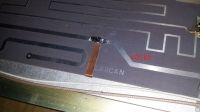
PA output board stripline sorting straps are stick-on copper foil, 1/4 inch wide x 3/8 inch long. Make sure to clean and tin the board prior to installing the straps. My first amplifiers converted had the straps soldered to be neat and tidy, minimal solder over the copper and edges. This looked good, but proved to create problems. The connections would fail over time, especially with very heavy duty cycle and switching. Arcing became visible at the straps and output power dropped considerably. The solution is to pour solder over the joints, piled high over each end, and even to bridge across the top between sides. It doesn't look as pretty, but solves the arcing problem and full power is restored.
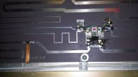
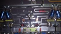 All 68pF capacitors in the original have been replaced with dual 33pF capacitors. Both capacitors for C13 are positioned away from C14 and C15 towards the FET as shown. These capacitors are rated at 500V.
 PA output 4-way combiner. For the lo/lo module, the original 24pF capacitors for C2 and C3 can be removed and positioned on either side of the 100nH output coil as C4 and C5.
Cut the traces as with the input section for new 43nH inductors. On some modules, the original 43nH inductors as specified in the writeup overheat ands smoke at 1kW output power. As a precaution I opted to change to a different coil on all amplifiers. See the parts list below for suggested replacements or wind your own. Use the original red inductors and wind around a 1/8 inch drill bit. Four turns for 43nH and ten turns for 100nH.
PA output 4-way combiner. For the lo/lo module, the original 24pF capacitors for C2 and C3 can be removed and positioned on either side of the 100nH output coil as C4 and C5.
Cut the traces as with the input section for new 43nH inductors. On some modules, the original 43nH inductors as specified in the writeup overheat ands smoke at 1kW output power. As a precaution I opted to change to a different coil on all amplifiers. See the parts list below for suggested replacements or wind your own. Use the original red inductors and wind around a 1/8 inch drill bit. Four turns for 43nH and ten turns for 100nH.
 Install the output strap in the same manner as the input strap. Clean and tin both the strap and circuit board. It gets positioned as shown.
I use OEM Larcan adapters for DC and RF while testing and converting the modules. If you replace the original DC connector and tie 50V directly to the main bus along the middle of the board don't forget the white wire that powers the bias board. If the wire is not connected the bias will not be supplied to the FETs. Output power will be limited and gain greatly reduced. SWR protection will not be present. Relocate the wire and solder to the circuit board next to the fuse or crimp a spade terminal to hold under a screw on the main bus.
Here is a
full parts list that I've compiled.
I can also convert your lo/lo or lo/hi amplifier. Cost of parts and shipping both ways extra of course.
If you have any other improvements or suggestions please pass them along to be shared with others. Please send pictures of your amplifier to show how it has been installed.
73
Warren
VO1KS
For purposes of disclosure and so on, some background is in order. I work in broadcasting and have installed, maintained, and repaired Larcan and other TV and FM transmitters for many years, and have attended Larcan factory training on two occasions. The modules and other parts pictured were obtained legitimately through other sources. The use of this equipment for amateur radio purposes should not in any way be interpreted as an endorsement by either my employer or Larcan, nor in any other way related to my regular work duties.
 These are serious commercial amplifiers, designed for 24/7 operation, not typical amateur radio equipment. Many of the hams on
Ping Jockey run Larcan amplifiers for EME and terrestrial digital modes.
The modules have been converted to 144MHz operation based on the initial work done by
Brian WA1ZMS. The procedure was further refined to produce a consistant 1kW module.
They have been modified with the serious 2M DXer in mind, ideal for today's punishing digital modes as well as SSB and CW.
Typical drive power is 20-25W input for 1kW output power. DC current requirement is roughly 40A @ 50VDC. For those interested in do-it-yourself, the details are supplied below. Power supplies can be found on eBay.
(search for "HP 253232 001" or "HP 2950")
Going price is roughly $40 or so, but with careful shopping and and some dealing you may find them for even less.
These are serious commercial amplifiers, designed for 24/7 operation, not typical amateur radio equipment. Many of the hams on
Ping Jockey run Larcan amplifiers for EME and terrestrial digital modes.
The modules have been converted to 144MHz operation based on the initial work done by
Brian WA1ZMS. The procedure was further refined to produce a consistant 1kW module.
They have been modified with the serious 2M DXer in mind, ideal for today's punishing digital modes as well as SSB and CW.
Typical drive power is 20-25W input for 1kW output power. DC current requirement is roughly 40A @ 50VDC. For those interested in do-it-yourself, the details are supplied below. Power supplies can be found on eBay.
(search for "HP 253232 001" or "HP 2950")
Going price is roughly $40 or so, but with careful shopping and and some dealing you may find them for even less.


