TORQUE TUBE REPLACEMENT
This page is dedicated to the saga that was my torque tube replacement. Like everything i have done on this car so far, it was a DO IT MY SELF PROJECT. It was quite an extensive one, even for a PROFESSIONAL SHOP to perform. (my last quote was for appx 2-3000 bucks) ....hence the DO IT MY SELF APPROACH..
Basically what happened was.......the torque tube is a hard steel tube in which the actual driveshaft for the car sits. The tube is a major structural component of the car as well, linking the engine in the front to the transmission in the rear. The drive shaft inside the tube is supported by a series of bearings. It is when these bearing fail or move inside the tube that you will start to hear the signs of a tube going bad. For me this sound was a faint WHIRRRRRRING noise that over a short period of time got very loud and annoying. Not having the facilites or the $$$$ at the time to fix it right away, the noise stuck with me for about 10months. It wasnt until October,with the purchase of a new house, that i finally had what i needed to start the job...SPACE....TIME....TOOLS and also the CONFIDENCE from repairing numerous other items up to this point.
Below are some pictures and notes of the steps i took to do the job!!! (remember..this is not the way it is set out in the manuals!!!!)
ANY INPUT...... v1uhoh@hotmail.com
The quick and dirty basic steps....
1. Raise car..remove rear wheels
2. Remove exhaust system and heat shields
3. Remove brake calipers, hang from the wheel well and remove the parking brake cable assembly.
4. Remove both axles
5. Remove all the wires, cables, fittings, braces, cooler lines from the transmission, brake assemblys and body that will hinder the tranny and suspension from being lowered freely.......this INCLUDES the front crossmeber and the aircleaner housing!!!!
6. Support the the transmission so when the suspension is lowered it will remain in place.
7. Remove all the bolts that anchor the tranny and suspension togehter and to the car..... lower the suspension assembly and move aside (the tranny will be caught by blocks you have underneath after about 1 inch of travel) .....I chose to completely remove my rear suspension..to clean it and have more room under the car.
8. Remove lower front bellhousing cover, exposing flywheel and front flexplate and pinch collar....GOOD TIME TO CHECK FOR PRELOADING AND THRUSTBEARING HEALTH!!!
9. Remove dust cover on bottom rear of Torque tube, exposing rear pinch bolt. If the bolt isnt aligned with the hole us a screw driver on the flywheel to gradually turn the engine to line the bolt up with the access hole. (TURN FLY WHEEL CLOCKWISE..when viewed from the front!!!) Remove the pinch bolt.
10. Lower the transmission just far enought to gain access to the 4 rear torque tube bolts....lossen them as well as the bracket for the kickdown cable on the upper part of the converter housing.
11. Once the 4 botls are free (they are VERY TIGHT AND AWKWARD!!), the tranny can be pulled aft and off.
12. Loosen and remove front pinch collar bolt.
13. Remove the 4 bolts securing the tube to the front bellhousing
14. slide tube aft and off!!!!
15. TAH DAH!!!!!!
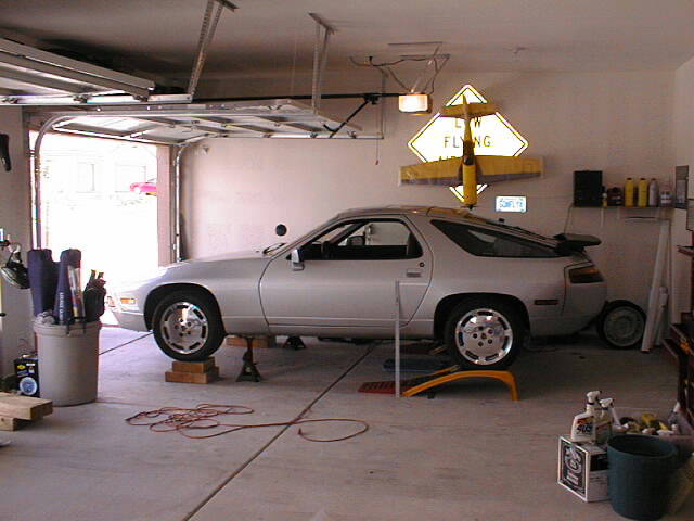
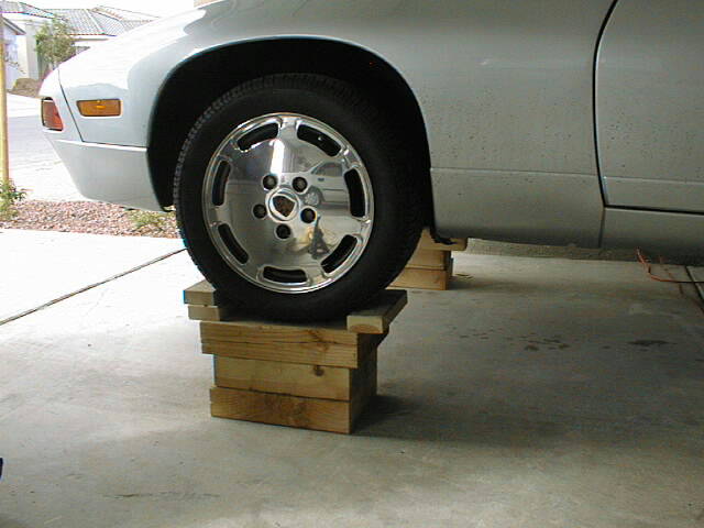
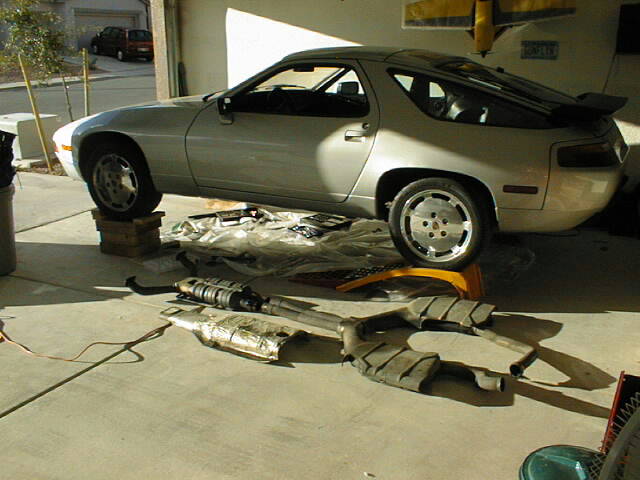
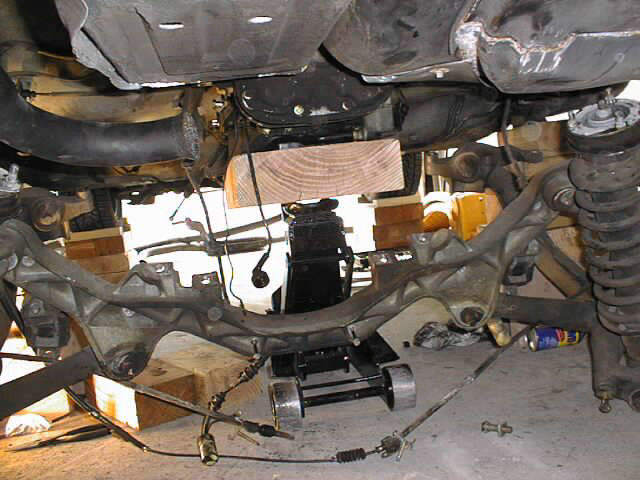
The pictures below just show how i had the car postioned to do all this work. The key to this was having the car comfortabley high enough and more importantly safely secured. I had both bases fully covered! The other important thing is to sit and study as you proceed what parts have to be removed so the removal of the tranny and suspension isnt hinderd.
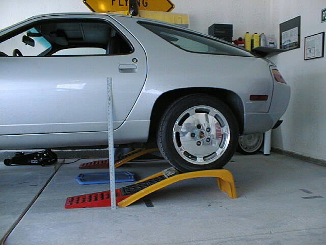 thats a 3 ft
ruler by the door...i have it at appx15-18 inches now
thats a 3 ft
ruler by the door...i have it at appx15-18 inches now
 ....it looks
kinda scarey but the car is in park, E-brake on and chocked at
the rears..the weight of the car is on the wheels/wood up front
and the ramps at the back (same as it would be on the ground appx
49/51). My goal is to get it safely another 4inches higher. This
was done with a single jack and alternatley lifting and putting
the wood under each wheel as i went up.
....it looks
kinda scarey but the car is in park, E-brake on and chocked at
the rears..the weight of the car is on the wheels/wood up front
and the ramps at the back (same as it would be on the ground appx
49/51). My goal is to get it safely another 4inches higher. This
was done with a single jack and alternatley lifting and putting
the wood under each wheel as i went up.
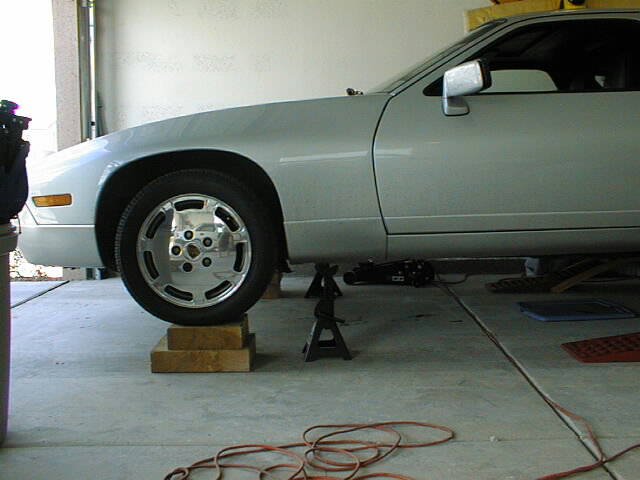
Well, I managed to get the car 4 inches higher with the aid of another solid wood block. I later anchored all the blocks together and screwed in a set of chocks to the top to eliminate any chance of the car rolling forward or back. After i was satisfied with the structural integrity of the set up i had i got under the car and went to work. The first thing i did was remove the muffler system...picutres below.. As a side note, the removal of the exhaust took no more than about an hour....very easily done!! (the rusty fittings were the only gremilins)
 the final
"chocked and secured" set up i used. The ramps and the
chocked rear wheels are out of view.
the final
"chocked and secured" set up i used. The ramps and the
chocked rear wheels are out of view.
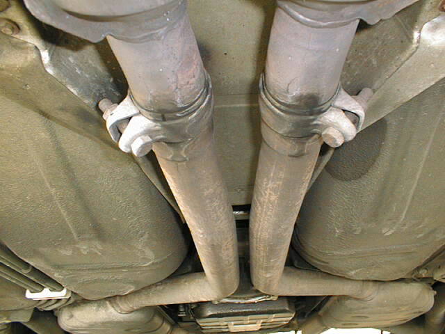 first thing i did was to undo the clamps on the joint between the
exhaust and the cat. converter. After i let them soak in WD40 and
with a little effort they broke loose. The nuts should be 15mm
and you will have to counter hold the other side.
first thing i did was to undo the clamps on the joint between the
exhaust and the cat. converter. After i let them soak in WD40 and
with a little effort they broke loose. The nuts should be 15mm
and you will have to counter hold the other side.
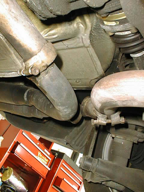 Your looking at the connection point of the RMB, these bolts came
off next. 2 X 13mm bolts. The RMB will have to be removed to get
the axles free of the car later
Your looking at the connection point of the RMB, these bolts came
off next. 2 X 13mm bolts. The RMB will have to be removed to get
the axles free of the car later
After the bolts were removed at these points i then removed the bolts for the rubber hangers that support the muffler system underneath. Once removed i simpley twisted, manipulated and pulled each muffler system off the CAT. The exhaust is somewhat heavy, so be careful! Of course i had to start the car to hear what it sounded like with just the CATs on : )
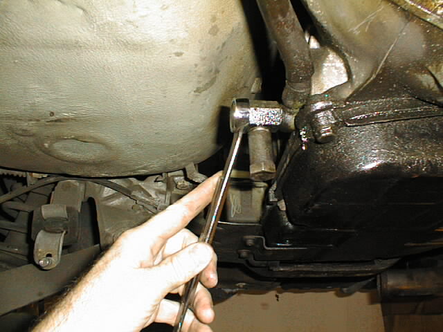
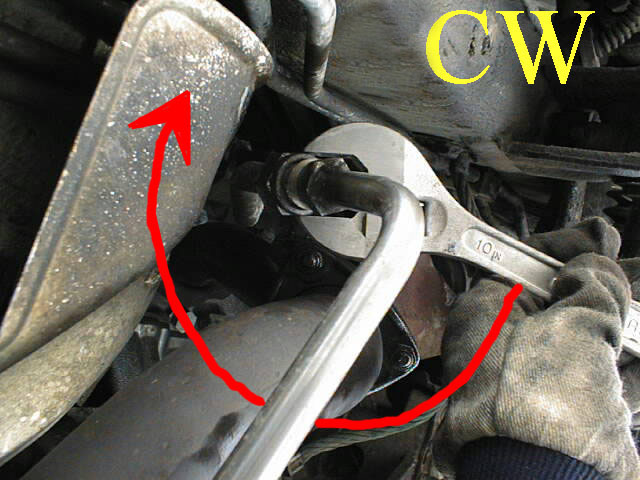 next was the front half of the exhaust system. I started here
with the fitting for the airpump that goes to the CAT....... AS I
NOTED....when viewd from UNDER THE CAR...the NUT TURNS CW TO LOOSEN!!! Although not pictured, use
an other wrench to counter hold the other fitting. While i was
working on this my WD40 was soaking the 6 exhaust flange bolts.
next was the front half of the exhaust system. I started here
with the fitting for the airpump that goes to the CAT....... AS I
NOTED....when viewd from UNDER THE CAR...the NUT TURNS CW TO LOOSEN!!! Although not pictured, use
an other wrench to counter hold the other fitting. While i was
working on this my WD40 was soaking the 6 exhaust flange bolts.
 here are the bolts on the exhaust flange...3 each side....13mm if
i recall (if not, 15mm)...the key is to uses 2 wrenches. Use one
wrench to counter hold the bolt. Instead of you doing the counter
holding, just allow the wrench to turn until it wedges its self
upagainst a solid object. From this point i used a hammer to
gentley break the bolt loose. TIP...use WD40 in advance of this,
it will help. The bolts were quite rusty!! I plan on replacing
all of these bolts and using ANTI SEIZE compound when i reinstall
everything. This will make things easier when it comestime to
install new headers and a CAT BY PASS at a later date : ) ( it
wont be too far away!!)
here are the bolts on the exhaust flange...3 each side....13mm if
i recall (if not, 15mm)...the key is to uses 2 wrenches. Use one
wrench to counter hold the bolt. Instead of you doing the counter
holding, just allow the wrench to turn until it wedges its self
upagainst a solid object. From this point i used a hammer to
gentley break the bolt loose. TIP...use WD40 in advance of this,
it will help. The bolts were quite rusty!! I plan on replacing
all of these bolts and using ANTI SEIZE compound when i reinstall
everything. This will make things easier when it comestime to
install new headers and a CAT BY PASS at a later date : ) ( it
wont be too far away!!)
 now this step is a little tricky. With 20/20
hindsight i would use a jack to help support the CAT as the
exhaust bolts we removed. I happend to be underneath the CAT area
at the time and just bent my knees up and kept it from dropping.
You DONT WANT IT TO HANG...as you can see the O2 sensor has to be
removed!!! The 02 sensor can also be disconnected from the front
passneger footwell area as well, giving you more slack in the
wire to work with.. With a little work i managed to get a wrench
on it and thankfully it broke loose easily from the threads. Out
it came and the CAT was lowered out of the
way!.................TA DAAA.....MUFFLER SYSTEM REMOVED!!!!!
now this step is a little tricky. With 20/20
hindsight i would use a jack to help support the CAT as the
exhaust bolts we removed. I happend to be underneath the CAT area
at the time and just bent my knees up and kept it from dropping.
You DONT WANT IT TO HANG...as you can see the O2 sensor has to be
removed!!! The 02 sensor can also be disconnected from the front
passneger footwell area as well, giving you more slack in the
wire to work with.. With a little work i managed to get a wrench
on it and thankfully it broke loose easily from the threads. Out
it came and the CAT was lowered out of the
way!.................TA DAAA.....MUFFLER SYSTEM REMOVED!!!!!
 Here
is a good view of the O2 sensor. Now would be a good time to
think about replaceing it perhaps......check for chaffing of the
wires as well!!!!!!
Here
is a good view of the O2 sensor. Now would be a good time to
think about replaceing it perhaps......check for chaffing of the
wires as well!!!!!!
 next step was to remove about a dozen bolts that support the HEAT
SHIELDS....if i recall they are 8 or 9 mm...and came out
effortlessly. After the shields were removed...the HOLY GRAIL of
my objective was in clear view...THE TORQUE TUBE!!!
next step was to remove about a dozen bolts that support the HEAT
SHIELDS....if i recall they are 8 or 9 mm...and came out
effortlessly. After the shields were removed...the HOLY GRAIL of
my objective was in clear view...THE TORQUE TUBE!!!
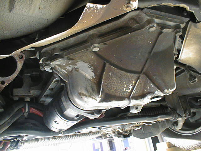
 this is the room i ended up having to work under the car...so
far,more than adequate! The Exhaust is all removed....next..the
biggy....the rear suspension!
this is the room i ended up having to work under the car...so
far,more than adequate! The Exhaust is all removed....next..the
biggy....the rear suspension!
DAY 2
Having some time to kill before i left on a trip and after recieving many emails from fellow "rennlisters" i went out to the gargage and sunk a 20 minutes of work into the car. In this step i removed the front lower housing/flywheel cover . After this is removed it exposes the flywheel and the front clamping bolt on the drive shaft . This is a key area where i will be taking a few measurements to see how far the collar moves on the shaft when the clamping bolt on the pinch collar is released. At this point i dont have the correct size HEX KEY (its BIG) so this measuring step will have to wait until i get the proper tool in a few days. In the meantime these are the pictures i have so far.
 this is what was removed..about 6-8 simple bolts
that broke free easily!
this is what was removed..about 6-8 simple bolts
that broke free easily!
 this is what is under the cover...the front end of
the drive shaft, pinch collar and bolt and the 4 bolts that
anchor the Torque tube to the front section of the car.Also seen
is the flywheel for the starter on the right.
this is what is under the cover...the front end of
the drive shaft, pinch collar and bolt and the 4 bolts that
anchor the Torque tube to the front section of the car.Also seen
is the flywheel for the starter on the right.
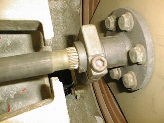 this is a great shot of the front clamping assembly
and where it attaches to the "triangular" flex plate.
this is a great shot of the front clamping assembly
and where it attaches to the "triangular" flex plate.
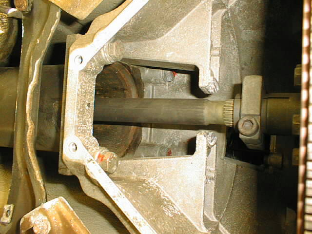
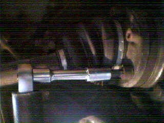
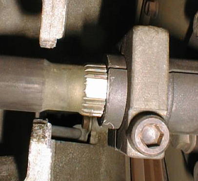 this is a close up of the pinch collar and splined
shaft. Upon recomendations from other list members i painted part
of the splined shaft white (used white out!)so when i loosen the
pinch collar bolt any movement will be noticed and made easier to
record. From what most of the guys say the collar will move aft
on the shaft when the collar pinch bolt is loosend.
Unfortunately, like a suspense movie, i dont have the correct
size HEX KEY at this time to fit the bolt you see and we are
going to have to wait until monday when i get back to see what
happens when it is released!!!!
this is a close up of the pinch collar and splined
shaft. Upon recomendations from other list members i painted part
of the splined shaft white (used white out!)so when i loosen the
pinch collar bolt any movement will be noticed and made easier to
record. From what most of the guys say the collar will move aft
on the shaft when the collar pinch bolt is loosend.
Unfortunately, like a suspense movie, i dont have the correct
size HEX KEY at this time to fit the bolt you see and we are
going to have to wait until monday when i get back to see what
happens when it is released!!!!
Besides the white paint i also took a sharp exacto knife and etched a nice crisp, fine line in the shaft where it meets the clamping collar.....more of a permanent mark than the paint
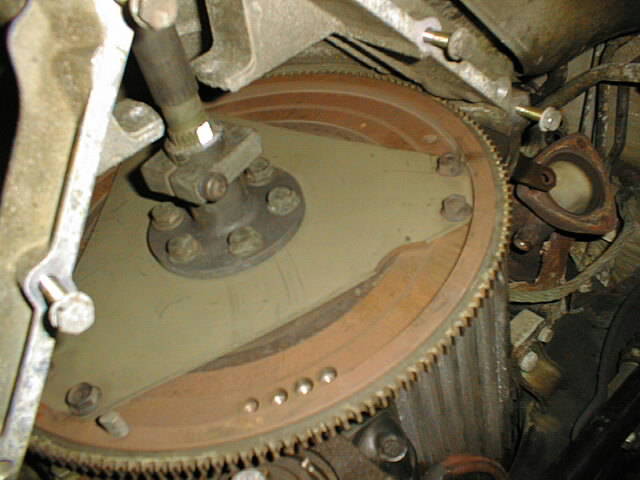
I also checked out the condition of my flex plate..seen below...as far as i can tell it looks in good shape...no warping or cracks around the reataining bolts any where. Also a good view of where i marked the splined drive shaft. Also NOTE the notch in the flexplate. From what I hear the assembly is balanced so you may want to install it back in the original postion in relation to the flywheel.
Stay tuned for drive shaft movemment........film at 11 : )
DAY 3
I returned home and bought a 8mm hex socket and got under the car. The pinch bolt on the collar was snugged but released easily. After i released the tension i slowly began to loosen it some more....eventually there was movement!! The entire collar assembly which is attatched to the forward flexplate moved AFT when the pressure on the bolt was completely released. It moved appx 4mm AFT. Hindsight is 20/20 and i wish i would have made graduated 1mm index marks on my white paint to make it easier to determine the EXACT amount of movement. 3-4 mm i think is a good estimate.
In summary my flexplate/drive collar moved AFT appx 4mm on the drive shaft when released.
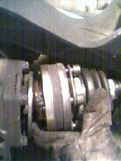
Below is a picture of a before and after. The after is placed over the before picture. It should make sense as you view it.
QUESTION NOW IS......WHAT DOES THIS ALL MEAN??? did it move too far...or not enough...in the correct direction.
My conclusion is that the drive shaft was placing FORWARD PRESSURE on the flexplate, moving the crankshaft in the engine forward.....into the THRUST BEARING??????(the rumored cause of thrust bearing failure in the automatics)
Now the next step is to measure the end play in the crank to see what the effects have been over time (see my other page on that subject).
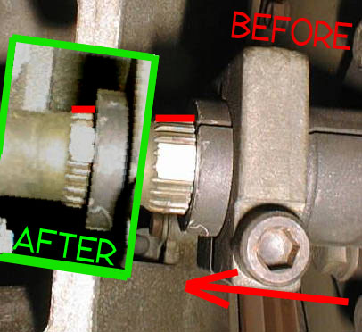 the red arrow shows the movement and the
amount can be judged by the WHITE OUT on the shaft and the RED
reference marks I superimposed on the shaft.
the red arrow shows the movement and the
amount can be judged by the WHITE OUT on the shaft and the RED
reference marks I superimposed on the shaft.
COMMENTS...ANYONE?
DAY 4
AXLE NUT and HALF SHAFT REMOVAL
Today was a big day, i managed to get that imfamous tightly torque axel nut off!! To sumerize this is how i did it.
I went to home depot and bought a 32mm WRENCH $$$$$(it will be returned when im done : )..not a socket (although i did have one anyway). .The reason i picked the wrench is the amount of torque involved and the stress on a straight bar/cheater bar or ratchet. The wrench was MORE than enough. I jacked the car up under the rear crossmember with the aid of some blocks, removed the ramps from underneath, removed the tires and lowered the car onto blocks under the jack points on either side. I then took the closed end of the wrench and placed it over the axle nut so that the arm extened just below horizontal. You will find that the wrench DOES HAVE ENOUGH OFFSET for this to work nicely...propper postion of the jack is quite essential...you will have about an inch worth of travel before the wrench arm hits the wheel studs...but..this is enough room to break the axle nut free. If you cant get the wrench positioned correctly just put the tranny in "N" and rotate the wheel so it works...put it in "P" and set the E BRAKE. Now place the jack under the end of the wrench and lift the car. The weight of the car being lifted VIA the wrench will break the AXLE NUT free!! It breaks free nice and slowly. Ones it does you can then use a 32mm socket (may still need a cheater bar) to finish the job!
When your all done...polish up the $32 wrench and return it : )
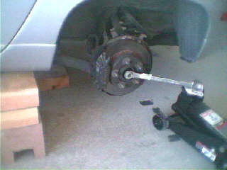 i placed a rag at the contact point of the wrench on the jack to
prevent damage to it....since it has to be returned.
i placed a rag at the contact point of the wrench on the jack to
prevent damage to it....since it has to be returned.
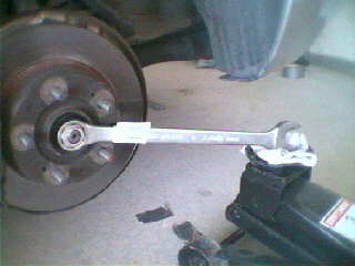 note the TAG still on the wrench... hee hee hee.... and the
postion of the wrench and the distance between the wheel
studs.....LIFT FROM THIS POINT...and the remove the nut.
note the TAG still on the wrench... hee hee hee.... and the
postion of the wrench and the distance between the wheel
studs.....LIFT FROM THIS POINT...and the remove the nut.
 after the axle nut was removed i took off the HALF SHAFTS.....8mm
hex socket on a ratchet and cheater bar to help. To gain access
to all the bolts just put the tranny in 'N" rotate the axle
until you can get to them all.
after the axle nut was removed i took off the HALF SHAFTS.....8mm
hex socket on a ratchet and cheater bar to help. To gain access
to all the bolts just put the tranny in 'N" rotate the axle
until you can get to them all.
After they are released the axle/shaft will simpley drop down. I let it hang then went to the stud where the AXLE nut came off and tapped it with a hammer....and......pulled it out!! TA DA!! thats it!! repeat on the other side!
Next will be to drain the tranny fluid...drop the trany fluid cooler lines...remove all the linkages/connection to the tranny ...drop the suspension ...a biggy!!!...so far all of the bolts have released easily in a "test" run....all this is in preparation to actually begin to lower the suspension and tranny...to remove the torque tube!
stay tuned!!
DAY 5.....
well...i think day 5??? At some point in this process my son was born and I lost the ability to devote DAYS to my work!!!......it became a matter of just a few hours here and there.
The next thing i did was to drain the tranny fluid. The plug for the drain is on the pan of the tranny, on the bottom. It is an allen key and loosens up with little effort. The fluid also should be drained in the torque converter as well. This done by rotating the converter (engine rotates CW when viewed from the front) to a point where you can gain access to the drain plug behind the rubber cap on the rear bellhousing area. After the fluid was drained i removed the tranny fluid cooler lines that run along torque tube. There are 4 places where the lines have to be removed...2 up front (passenger side, close to where the TT mates with the flywheel housing...they may be hidden under some foil insulation) the other 2 are located on either side of the transmission case. The aft ones are easy to get off but the 2 front ones can be tricky....a 17 and a 19mm wrench will be needed to counter hold the fittings..this is a MUST!! After the fittings are loose you will probably have more residual fluid in the lines that will drain...have saftey glasses on and something to contain the fluid. At this point you may as well undo all the large dia. hose clamps around the TT that retain the cooler lines. This will alow them to drop free later.
 one fitting on the tranny....the other is on the other side
tranny cooler lines with the foil peeled back...wrenches counter
holding.
Next there are numerous links and fittings that are attatched to the tranny that have to be removed inorder for it to be dropped as well as a few items under the hood that have to be taken care of.
 driver's side has most of the things that need to be
removed....the passenger side has the kickdown cable and on the
back of the final drive case you will find the impulse sender for
the speedometer.
driver's side has most of the things that need to be
removed....the passenger side has the kickdown cable and on the
back of the final drive case you will find the impulse sender for
the speedometer.
Under the hood remove the airtubes, entire air filter housing and cross brace. This is VERY IMPORTANT as when you lower the tranny with the TT attatched the entire engine assembly will tilt aft! There is NOT much room behind the engine or above it and the aircleaner and oil filler neck will be damaged when the motor tilts aft!! (you break the filler neck gasket..you have to take the intake manifold of to replace it!!!...not fun!!)
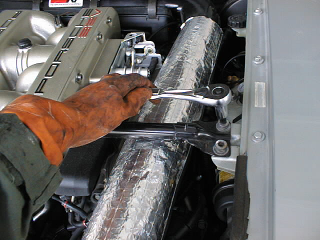 with the weight on the front wheels still, i removed the
x-brace...then the tubes..and aircleaner assembly
with the weight on the front wheels still, i removed the
x-brace...then the tubes..and aircleaner assembly
Like i mentioned earlier, the tranny itself has quite a few items to be disconnected......in all honesty i dont know what all of them are for but you will see that they MUST be removed for the tranny to be lowered. As i found later there is wire on the back of the trannsmission case (final drive area) that can easily missed....this is the magnetic pickup for the speedometer..
 Impulse sender......on final drive case
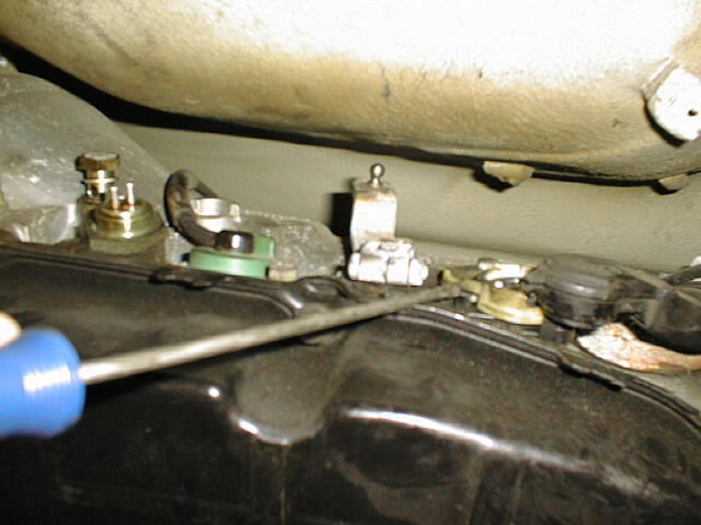
 On
the passenger side of the case, just in front of the fluid
resivour you will see the KICK DOWN CABLE and where it joins the
tranny. This is one of the cables i removed from the throttle
mechansim under the hood (where all those 4 cables
meet...accel..cruise..kickdown..and throttle body) Having this
free allowed a bit more cable play at the end i was working at.
The plastic retaining clip for the kickdown cable in the tranny
housing can be tricky. There is a small plastic tab that you
squeeze and the assembley should pull straight up and out. I just
carefully manipulated it until it came loose.......CAREFULL the
plastic is very brittle!! IT DOESNT REQUIRE ANY PRYING FROM A
SCREW DRIVER!! The goal in this whole series of steps is to
remove all the things attachted to the tranny...that simple
really!!
On
the passenger side of the case, just in front of the fluid
resivour you will see the KICK DOWN CABLE and where it joins the
tranny. This is one of the cables i removed from the throttle
mechansim under the hood (where all those 4 cables
meet...accel..cruise..kickdown..and throttle body) Having this
free allowed a bit more cable play at the end i was working at.
The plastic retaining clip for the kickdown cable in the tranny
housing can be tricky. There is a small plastic tab that you
squeeze and the assembley should pull straight up and out. I just
carefully manipulated it until it came loose.......CAREFULL the
plastic is very brittle!! IT DOESNT REQUIRE ANY PRYING FROM A
SCREW DRIVER!! The goal in this whole series of steps is to
remove all the things attachted to the tranny...that simple
really!!
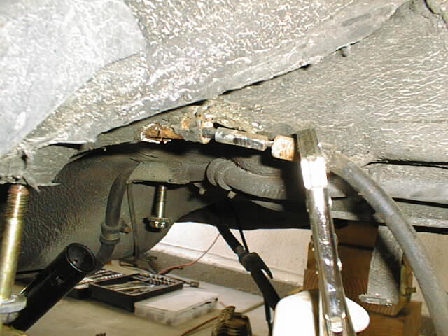
I also applied this same process to the rear crossmember.....looking for various lines, cables or fittings that would interfer with the lowering of the tranny. One of them was the parking brake cable assembley. When you look at it you will see it is attatched at several points on the crossmember all of which came free easily.
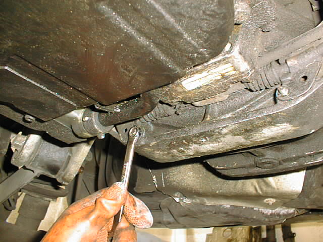 LOOK
AT THE MUCK AND DIRT UNDER THERE!!!! It doesnt look like that any
more!!! : )
LOOK
AT THE MUCK AND DIRT UNDER THERE!!!! It doesnt look like that any
more!!! : )
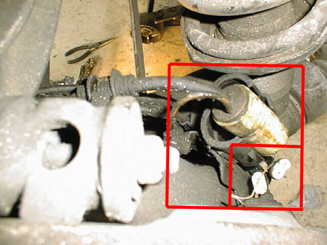
In order to completley free the suspension from the car you should disconnect the parking brake cable from inside the car and pull it out from the driver side wheel well. You will find that just pulling the cable wont work. There is a fitting inside the wheel well that will prevent the cable from being pulled through fully. The fitting is somewhat hidden under some under-coating...just follow the cable to the entry pont in the wheel well a place a pair of vice grips on the last 1/2 inch of the fitting and begin to twist. You should find that it will turn and you will slowly be able to pull it out.
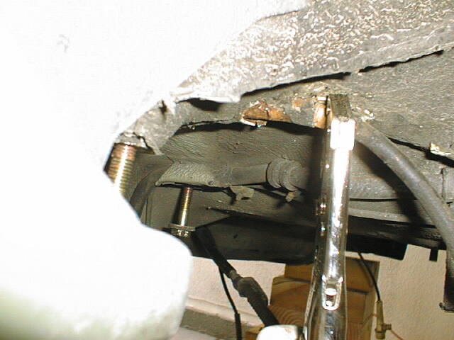
above right...you can see the SQUARE fitting that wouldnt slide through the ROUND cable sleeve
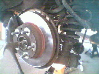
Speaking of brakes, i also removed the calipers from the suspension and hung them via wire from the wheel well. Like the tranny you will find that there are a few connections that have to be removed from the brakes to allow them to hang free of the rear suspension.....in a nut shell, everything but the brake lines are removed,
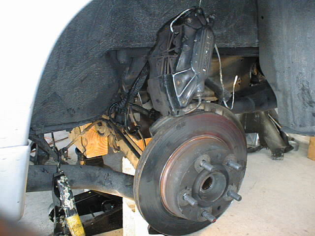
At this point the tranny fluid is drained and its fittings removed....parking brake cable, lines etc have been removed from the rear crossmember and the rear calipers have been removed.......the suspension AND transmission are being supported underneath by wooden blocks and a floor jack in preparation for be released and lowered.
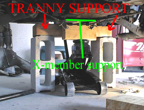
The way i worked this was.....the rear crossmember would be dropped with the tranny attatchment bolts already removed (the tranny rests ON the crossmember). I made a support structure to "CATCH" the transmission (still attatched to the Torque tube) after the crossmember had been lowered about 1 inch. After the tranny had been lowered the 1 inch and became supported i continued to lower the crossmember with the floor jack until it could be removed.
The next step was to use the jack to lower the transmission far enough where i could gain access to the upper attachtment bolts on the torque tube and the steel kick down cable bracket.. Using a nice large flat plank of wood i placed it under the tranny PAN and used the jack to lower the tranny to a point far enough.
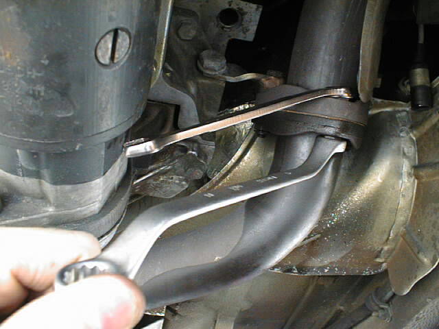
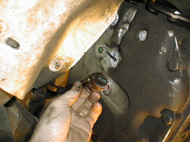
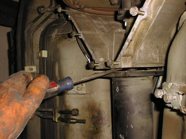
.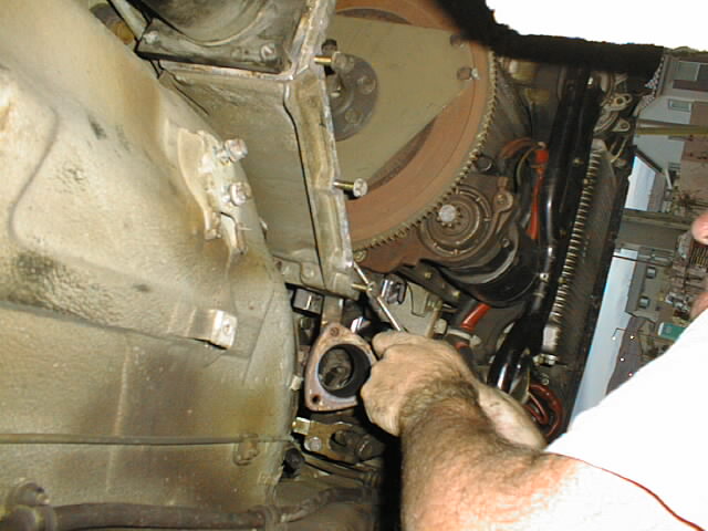 sorry about the camera angle!! ....using a screw driver to turn
the flywheel to line up the REAR bolt on the pinch collar.
(thanks to Dad for that idea)
sorry about the camera angle!! ....using a screw driver to turn
the flywheel to line up the REAR bolt on the pinch collar.
(thanks to Dad for that idea)
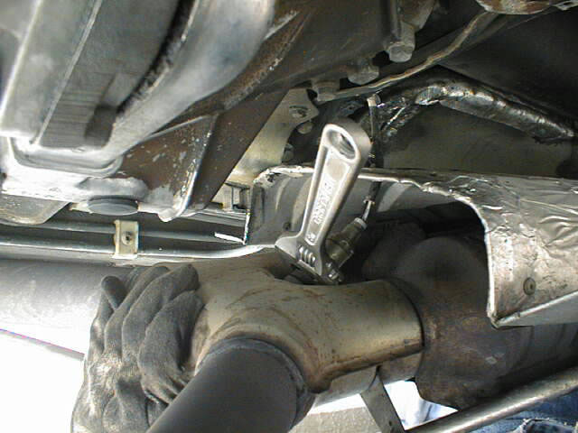
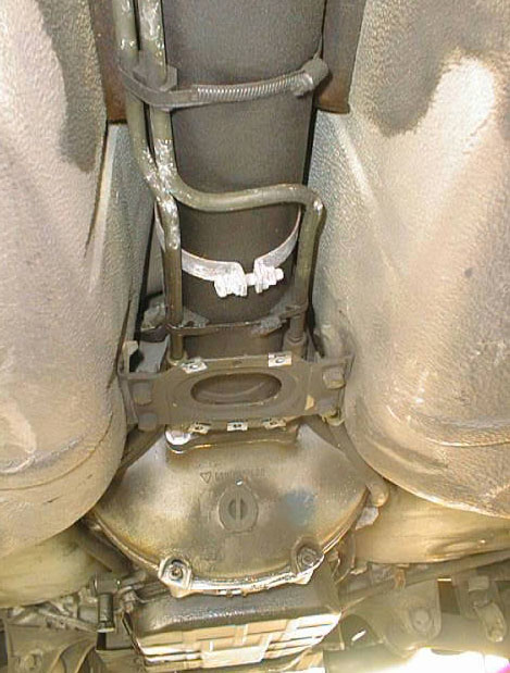
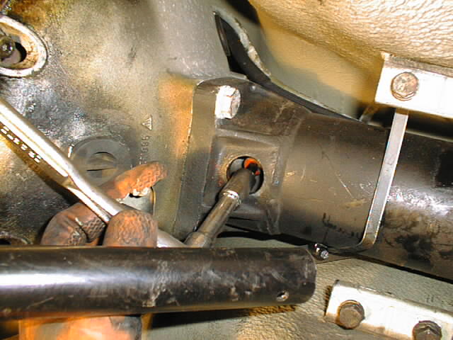 using the hex socket through the access hole to loosen the pinch
collar bolt (REMOVE THE BOLT COMPLETELY)....at this point, the
other end of the TT is still securely mounted to the front
bellhousing so it wont pull away when we pull the tranny AFT . In
this picture you can also see one of the bolts that mount the TT
to the tranny....these are torqued to some 80ftlbs and were very
tough to break free, especially in the limited room i had to turn
the wrench on the upper 2. Be patient with these 4 bolts....they
are tough!!! When we pull the tranny aft the goal is to pull the
rear splined part of the drive shaft from the rear collar (make
sense???) thus separating the tranny from the Torque tube and
shaft! I used a wide flat head screwdriver to help separate the
tube from the rear bellhousing then pulled the tranny aft.
BECAREFUL WHEN IT DOES SEPARATE AS THE TRANNY WONT BE BALANCED BY
ANYTHING!!..it will just be held up by the jack!!
using the hex socket through the access hole to loosen the pinch
collar bolt (REMOVE THE BOLT COMPLETELY)....at this point, the
other end of the TT is still securely mounted to the front
bellhousing so it wont pull away when we pull the tranny AFT . In
this picture you can also see one of the bolts that mount the TT
to the tranny....these are torqued to some 80ftlbs and were very
tough to break free, especially in the limited room i had to turn
the wrench on the upper 2. Be patient with these 4 bolts....they
are tough!!! When we pull the tranny aft the goal is to pull the
rear splined part of the drive shaft from the rear collar (make
sense???) thus separating the tranny from the Torque tube and
shaft! I used a wide flat head screwdriver to help separate the
tube from the rear bellhousing then pulled the tranny aft.
BECAREFUL WHEN IT DOES SEPARATE AS THE TRANNY WONT BE BALANCED BY
ANYTHING!!..it will just be held up by the jack!!
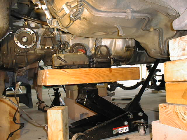
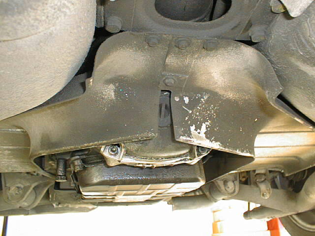
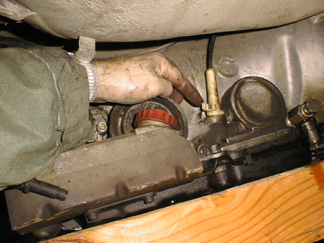
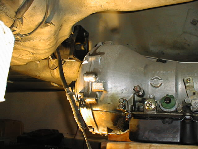
All supported and ready to be pulled aft.
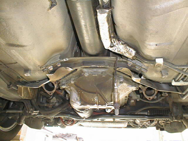
 This shows the front bell housing but you should get the
idea......same idea for the aft area. Im using a screw driver to
help separate the parts. You will find that the tranny will have
to be lowered a bit before you pull it aft. This will cause the
WHOLE TUBE ASEMBLY and the ENGINE ASSEMBLY to tip down. (THIS IS
WHY THE FRONT CROSS BRACE AND AIRCLEANER MUST BE REMOVED). On my
car there just wasnt enough clearance behind the tranny in its
normal "LEVEL" postion to allow for the splined shaft
to be completely pulled free and out from the rear collar. The
heat flashing around the gas tank and battery compartment
interfered slightly.
This shows the front bell housing but you should get the
idea......same idea for the aft area. Im using a screw driver to
help separate the parts. You will find that the tranny will have
to be lowered a bit before you pull it aft. This will cause the
WHOLE TUBE ASEMBLY and the ENGINE ASSEMBLY to tip down. (THIS IS
WHY THE FRONT CROSS BRACE AND AIRCLEANER MUST BE REMOVED). On my
car there just wasnt enough clearance behind the tranny in its
normal "LEVEL" postion to allow for the splined shaft
to be completely pulled free and out from the rear collar. The
heat flashing around the gas tank and battery compartment
interfered slightly.
 after being lowered/tilted and pulled....OFF IT
COMES!!!........it's quite heavy and very awkward to move around
as well, as a solution I ended up putting it on my crawler to
move it
after being lowered/tilted and pulled....OFF IT
COMES!!!........it's quite heavy and very awkward to move around
as well, as a solution I ended up putting it on my crawler to
move it
Next step was to loosen the 4 bolts that hold the TT to the front bell housing and the pinch collar bolt. After these were removed it was just a matter of using the screw driver like i did earlier to pry the tube and shaft from the front flexplate and pinch collar.
TAH DAH!!!!!!! TORQUE TUBE REMOVED!!!!!!
REINSTALLATION
In a nutshell reinstallation is basically a reverse process, however, there are a few gottyas that i discovered that you should think about....theses are in no particular order.
Have all the parts you need ready to go...gaskets...torque tube...hoses....etc
Take a look at the pictures/notes you took earlier ...you want to install things as close to the original postion as you can.
Make sure the end of the torque tube protrudes 2mm +-.5 as the manual states...and that this values hold true AFTER you have it bolted to the forward collar and BEFORE you slide the tranny on the back.!
When you install the tranny onto the tube, DONT......DONT...put the pinch bolt in the rear collar! Not even loosely, the shaft will slide on about 3/4 of an inch then will stop. You will be left scratching your head for 1/2 hr trying to figure out what is stopping it from going all the way (the bolt isnt even tight..it is just in the collar). The splined shaft actually has a grove around its circumference that the pinch collar bolts passes along. The bolt will go in effortlessly through the small hole in the bottom of the tube later.
My BIG concern was to not have the central shaft move inside the tube and along the bearings thus knocking things out of alignment. To prevent this, after the front tube flange was bolted to the rear bellhousing, i measured the clearance at the end (2mm +-.5) then tightened down the front pinch bolt on the collar. This assured me that the shaft would not slide along the inside of the tube if i accidently pushed the tranny on misaligned. Any movemtent or pushing would be transmitted to the flexplate and be very limited in distance. After installation, I made a point of marking the proper position of the shaft in the forward collar for reference later when looking for any unwanted movement..
BASICALLY THESE ARE THE STEPS I TOOK...........
1. Install torque tube and mount it to the forward bell housing....use what ever means you have to raise it up into postion. I did this job by myself and used a floor jack and some wooden blocks to do the trick. I also used some silicone spray to help the splined shaft slide in the collar. Make sure the steel pins on the bell housing line up with the holes in the Tube then torque the 4 bolts to specs. Before you do this make sure that the insulating foam and cable are routed correctly on top of the tube.
2. Install pinch bolt on fwd collar and torque to specs...i took mine to 66ftlbs.
3. Raise tranny and slide the rear collar onto the splined shaft...again using an ample amout of lubricant. To make this easier you will have to pull down on the TT to get the ends to meet. Again, you will find that the heat shields near the gas tank and battery compartment will interfere if you try to just rasie the tranny straight up and into postion and then push it on. You have to angle it slightly.
4. Install the 2 lower bolts that mount the tube to the converter housing....tighten them down SNUG....make sure the steel pins/collars on the converter case slide into the holes on the tube.
5. By what ever method you use, lower the tranny slightly (now attached firmly to the tube by the 2 lower bolts) to a point where you can get the 2 UPPER mounting bolts in the tube....and snug them down.
DONT FORGET!!!!.......At this time reattatch the steal kickdown cable shroud to the the converter casing.
6. Go back now and torque the 4 rear mounting bolts to 87ft/lbs......its alot but they will easily do it! Trust me there is JUST enough room to get the torque wrench in there!
7. Now you can reroute and secure all the cables, wires and tranny cooler lines back on the tranny and the tube.
8. Now raise the tranny up into to a normal level postion. Now, by what ever means you use, support it there as you will next add the rear suspension underneath it.
9. install the rear pinch bolt in the collar and torque it down to 66ft lbs.
10. Thats it!! the drive train is again one!!
11. Next i had to reinstall the entire rear suspension. To do this i placed it on my crawler and slid it under the car then got my floor jack underneath it.
12. Before you rasie the suspension, make sure there arent any cables, wires or fittings that will interfere.
13. Once everything is clear, raise the suspension using the jack, checking its progress periodically. You dont want bend or stretch anything as you rasie it.
14. At some point check the bolts in the trunk area that mount the shocks/springs, making sure they protrude through the holes. If they do, attatch the bolts and torque to specs.
15. Underneath, make sure the holes in the suspension line up with the holes in the body. If they do, thread the bolts in by hand, then torque them down to specs ( you DONT want to strip these threads!!) If they dont line up, snug them down very slightly, just enough to hold the suspension up yet loose enough where you can adjust the postion with a tap of a mallet. I used the marks in the body left behind and the ones i had made earlier to help relalign everything during installation.
16. Install the brake calipers on the wheel assembely and route the cables and wire appropriately.
17 Install and scure the parking brake cable.
18. Install the axles and the 32mm nut....i snugged mine down then when the car was on the ground. I used my 32mm wrench which is nearly 2 ft long and my body weight 185pds and a little physics. Torque=force X distance...... my 185pds applied at nearly 2ft should give me over 300ftpds of torque to the bolt...which it requires!! I stood on the end of the wrench basically..then bounced on it slightly!! Very unorthadox...but it worked!!
19. If you have drained the differential oil, refill it
20. Fill the transmission with new fluid follwing the manuals procedures.
21. Step back and take the time to look at the entire installation making sure you have things tightened, secure and routed correclty
22.....come to the realization that you just did all this your self and saved about $3000!!!!
23. THATS IT!!!!!
24. NO WHIIIIIIIIIIIIIIIIIIIIIIIINing!!!!!!!!!!!!!!!! Just the BWAAAAAAAAAHHHHHHHHH of the exhaust note!
Of course there are many steps in these procedures that can be approached differently or that can be accomplished by other means but this is how I ...ME...."Mr Scraped Knuckles".....did the job! Consider this page a BASIC overview of what needs to be done. On and off it took about a month and a half doing an hour here and there when I could. Remember that these are not QUOTED STEPS FROM ANY MANUAL....but rather from my head!!...LOL...so work at your own liability...you have been warned!!!!! haha.
In any case, I hope the pictures that I have shown above and the steps that I took will help a few out there if they decide to do the job themselves. The key thing to remember is that THIS JOB CAN BE DONE WITH OUT TAKING THE CAR TO THE SHOP!!!!! A few items you may have to "farm" out, but I have now seen that alot of this work, this being an extensive job, can be accomplished by the "do it yourself wrench"
Lastley, thanks to ALL of the folks on the RENNLIST 928 email boards and the folks at 928 International for the numerous answers and solutions sent my way when a question/problem crept up.
Hope the info helps........
Time for a beer! : )
click the logo for parts by....
![]()