ENGINE PROJECT PICS
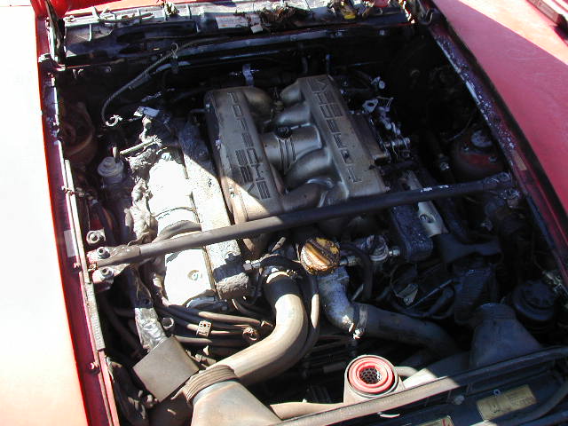
I bought this motor to be used as a "base" engine for my supercharger project.
The plan: Take the stock 10:1 CR S4 motor, machine the pistons to remove 6cc and end up with a 8.7:1 CR S4 motor using all the original matched components that came out of it. Rings, bearings and gaskets of course will all be replaced but the basica "metal internals" of the motor will be all stock.
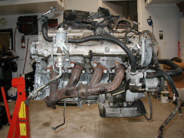
The motor came out of an 87s4 auto that had 37k miles on it. (thats what they said at least). carfax seemed to back up this figure and so far what i have seen of the motors guts its looking like it indeed was a low mileage engine.The fire seemed to be located near the aft part of the motor, under the airbox assembly. My gut instinct is that it was the fuel supply line that feeds into the Fuel pressure regulator. The fire destroyed the wiring harnes, MAF electronics and various rubber and foam pieces. The metal and the "guts" of the motor are in fine shape as far as i can tell up to this point. All the belts up front were not damaged, the entire T-belt system is intact and shows no sign of fire or even smoke. All in all, i think i ended up with a pretty good engine.
Below are pictures i have taken during the process. They're there for me to just document what ive done and more so to aid me in how it all goes back together!!
Ive added notes here and there...
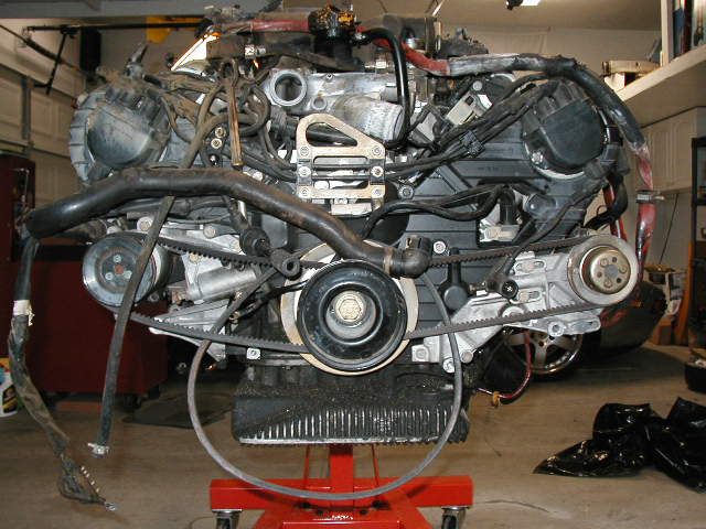
The carnage.....
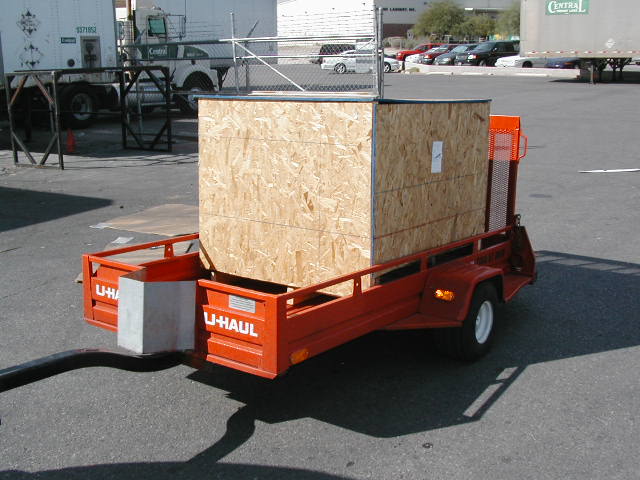
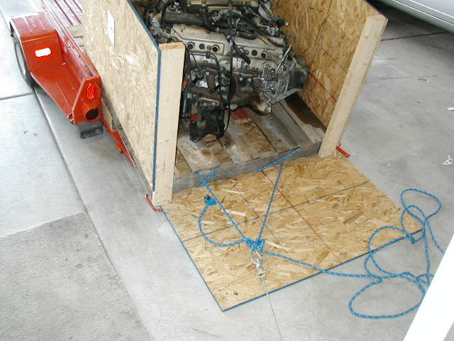
Friday 10-3-03.....I pick up Pandoras Box....
 ...Ok,
when i guy works by himself, he has to improvise. A
come-along....rope...a 2x4...and a wife out of the house for the
day : )
...Ok,
when i guy works by himself, he has to improvise. A
come-along....rope...a 2x4...and a wife out of the house for the
day : )
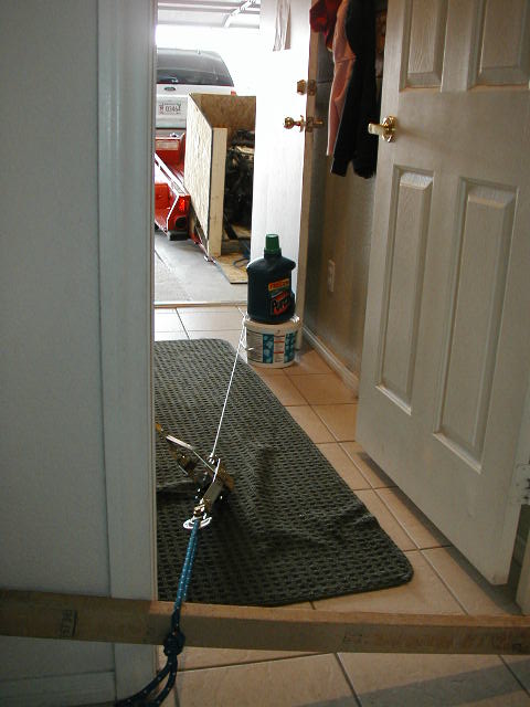 ..i tipped
the trailer then used the come-alog to drag the engine out..using
a 2x4 between the door posts as leverage. Worked great!!
..i tipped
the trailer then used the come-alog to drag the engine out..using
a 2x4 between the door posts as leverage. Worked great!!
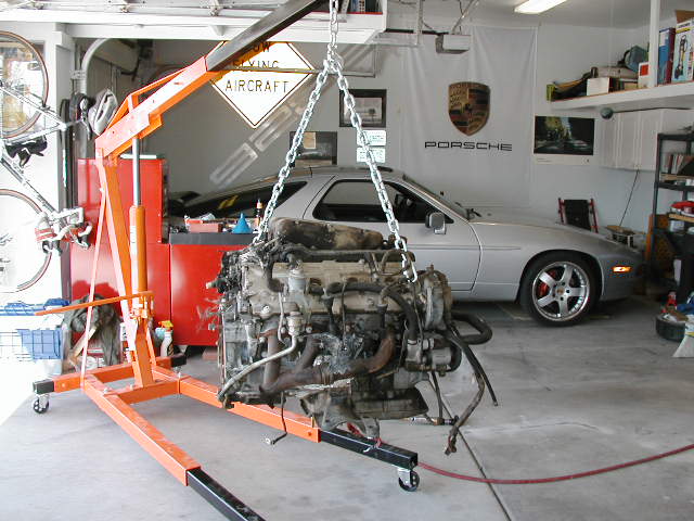
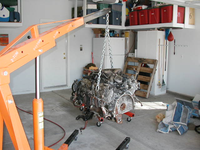 2 ton
harbor freight hoist, borrowed from another local 928
owner..thanks a million Andy and Phil!
2 ton
harbor freight hoist, borrowed from another local 928
owner..thanks a million Andy and Phil!
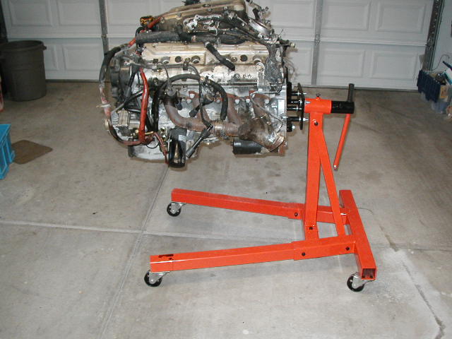
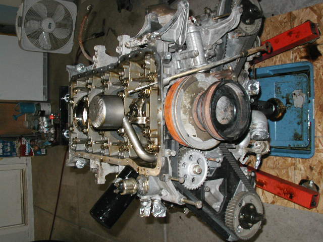
 engine
stand mounts...and my OLD concrete floor, now covered with www.racedeck.com
engine
stand mounts...and my OLD concrete floor, now covered with www.racedeck.com
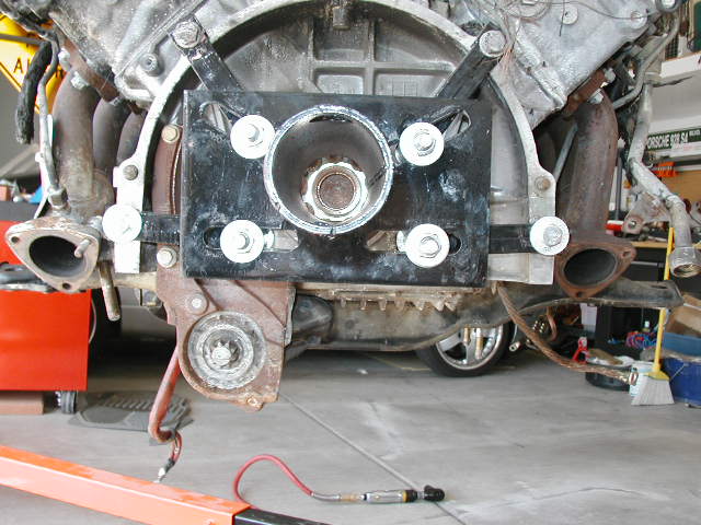
 TIP:
attatch the hardware to the engine first, then slide the post
into the stand. You will have a VERY hard time finding long
enough M12x1.5 bolts (2 top ones) to pass through the brackets
into the block. A suggestion from Adam B to basically trun the
brackets around worked great! Some new bolts and washers(a must)
from HomeDepot and i was set.
TIP:
attatch the hardware to the engine first, then slide the post
into the stand. You will have a VERY hard time finding long
enough M12x1.5 bolts (2 top ones) to pass through the brackets
into the block. A suggestion from Adam B to basically trun the
brackets around worked great! Some new bolts and washers(a must)
from HomeDepot and i was set.
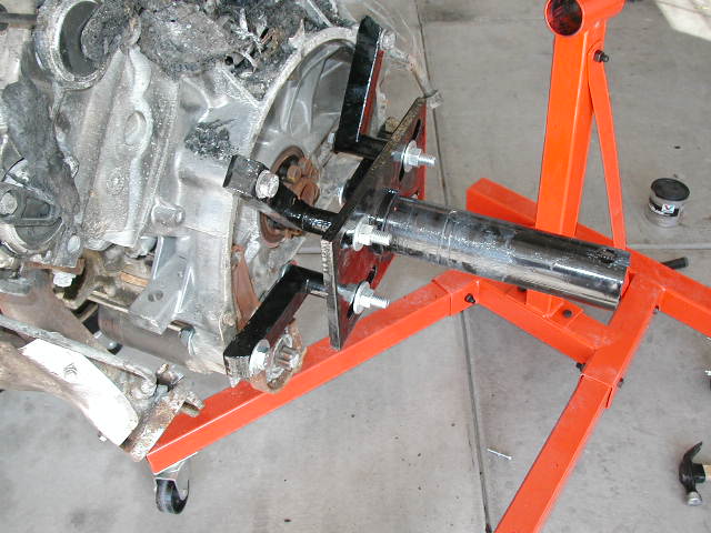
 REPEAT
AFTER ME: GET THE 2 TON STAND!! I did and im glad i did! this
motor is heavy. It doesnt weigh 2 tons but none the less it is
heavy!
REPEAT
AFTER ME: GET THE 2 TON STAND!! I did and im glad i did! this
motor is heavy. It doesnt weigh 2 tons but none the less it is
heavy!
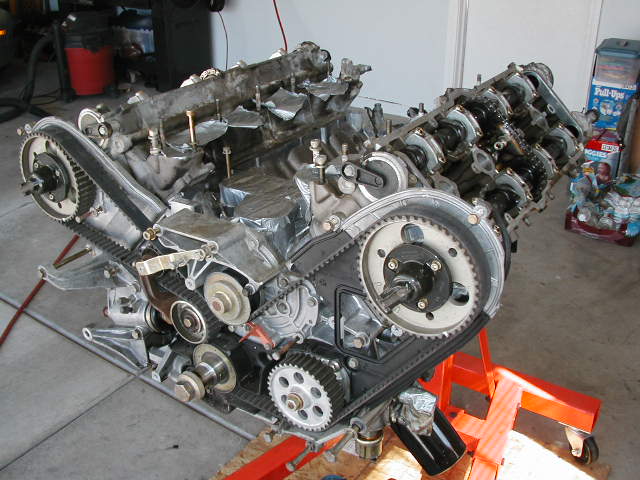
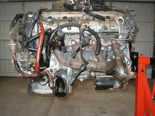 a bunch
of pictures for reference
a bunch
of pictures for reference
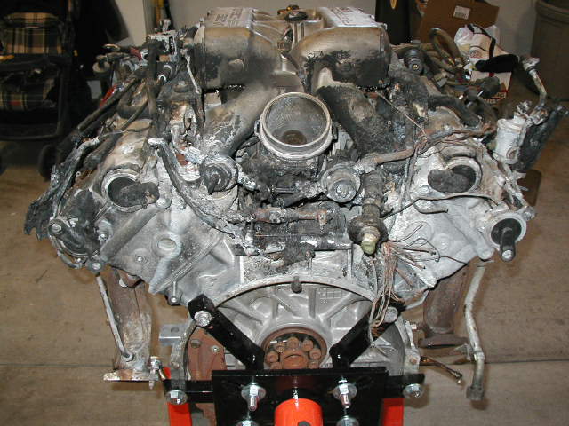 ...bummer!
Monday10-6-03
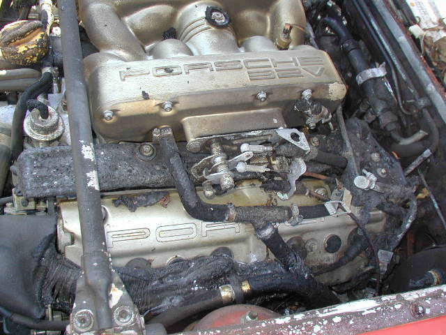
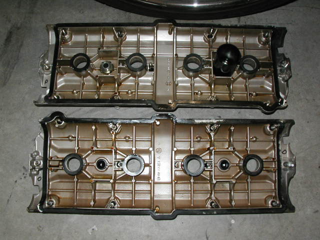
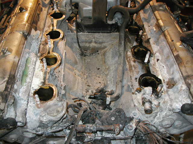 ...no sign
of any oil in the V. Just lots of DRY CHEM fire ext agent.
...no sign
of any oil in the V. Just lots of DRY CHEM fire ext agent.
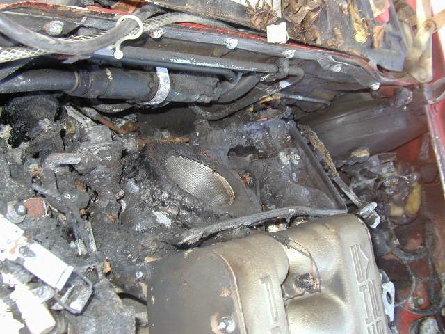
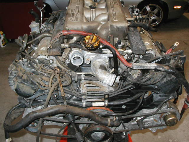
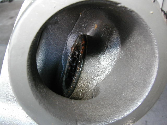
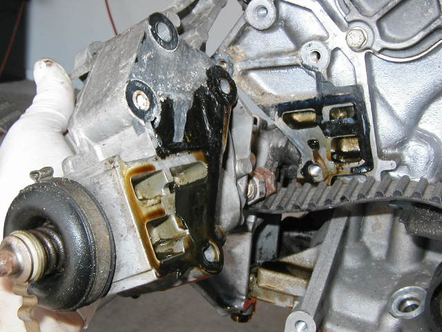
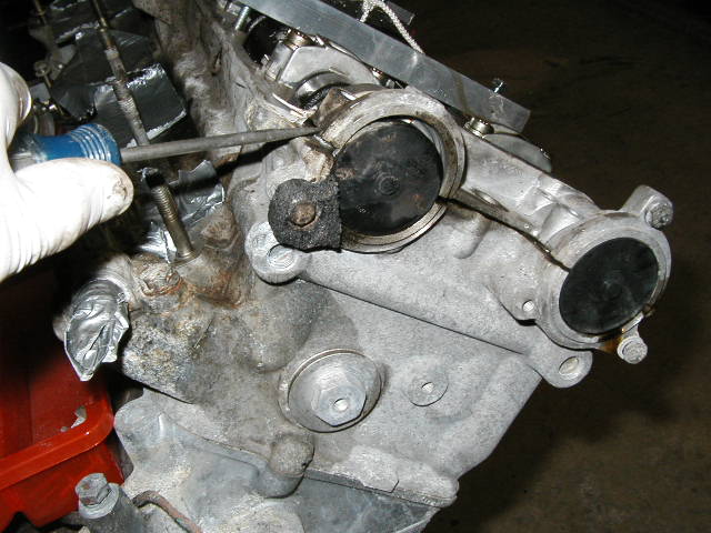
 This is
the general area where i think the fire started. It seemed to
have suffered the most heat damage.. The roundish object on the
right is the pulley leading to throttle body
This is
the general area where i think the fire started. It seemed to
have suffered the most heat damage.. The roundish object on the
right is the pulley leading to throttle body
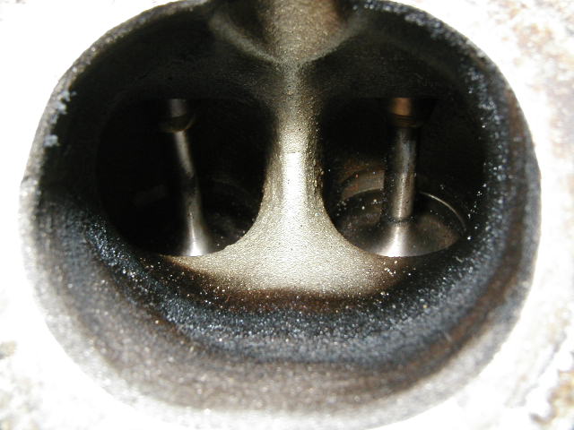
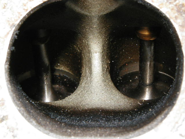
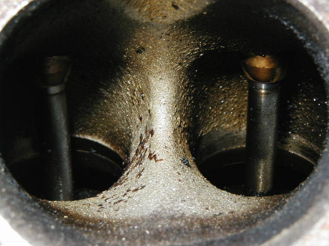
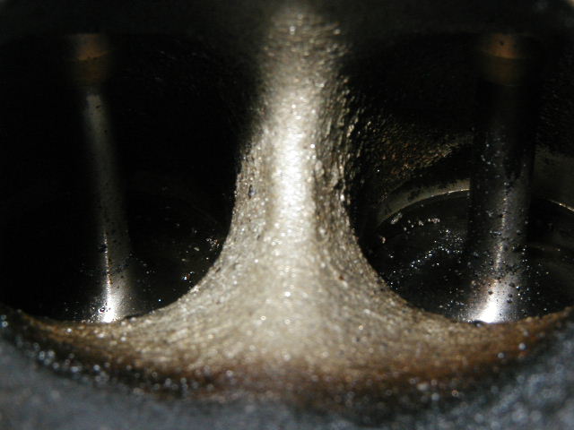
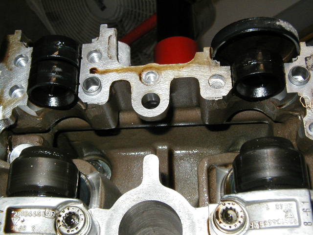
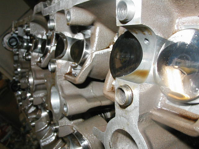
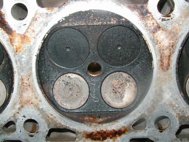
Intake valves...great shots showing what a rough finish is left from the casting. The valves were actually very clean. The ports werent as bad as i have seen on others. All the little particles you see are from a quick blow out with the air hose. Didnt work too well. Time to make a modified tip for the shop vac! My next thing on the list is to clean all these out...carefully!
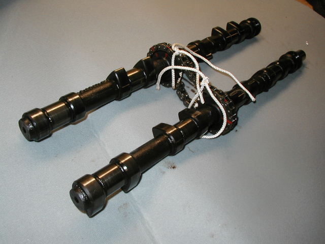
Camshafts................... I was VERY happy when i saw the condition of these....smooth..no pitting..or wierd discoloration. It all really look brand new!
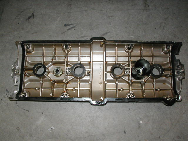
 I believe
that is the origanl factory sealant in the corner (white). Used
to seal the valve covers per the shop manuals.
I believe
that is the origanl factory sealant in the corner (white). Used
to seal the valve covers per the shop manuals.
Tuesday 10-7-03
 After
sealing up all the "holes" i pressure washed it,
removing debris, soot, dirt and oil. It really came up clean!(
the oil pan and valve covers were still at the time of the
cleaning.. : ) )
After
sealing up all the "holes" i pressure washed it,
removing debris, soot, dirt and oil. It really came up clean!(
the oil pan and valve covers were still at the time of the
cleaning.. : ) )
 as far as
i could tell, there are no scratched or blemishes on the cylinder
walls. Ill be able to check this better after the intake ports
are clean, i check the timing belt and do a leak down check. I
should be able to postion each piston at TDC very easily to get a
good look.
as far as
i could tell, there are no scratched or blemishes on the cylinder
walls. Ill be able to check this better after the intake ports
are clean, i check the timing belt and do a leak down check. I
should be able to postion each piston at TDC very easily to get a
good look.
 exhaust
ports......
exhaust
ports......
 you could
eat of these things. No flaking or fading. This is how they
looked when i turned them over for the first time
you could
eat of these things. No flaking or fading. This is how they
looked when i turned them over for the first time
STAY TUNED..................................
Tuesday 10-7-03
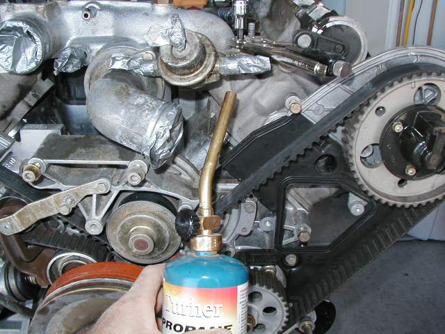 Two stuck
bolts so far. This one on the water manifold. A little bit of
heat and some vice grips for some gripping power to revent
strippping the head on the hex bolt. A constant pressure applied
for abotu 30 seconds and it slowly gave way....PHhhhheeeeeew!
Two stuck
bolts so far. This one on the water manifold. A little bit of
heat and some vice grips for some gripping power to revent
strippping the head on the hex bolt. A constant pressure applied
for abotu 30 seconds and it slowly gave way....PHhhhheeeeeew!
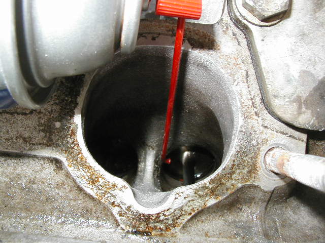
 Fear not
about droping anything in the oil filler neck! As Jonny Carson
used to say..."I did not know that"
Fear not
about droping anything in the oil filler neck! As Jonny Carson
used to say..."I did not know that"
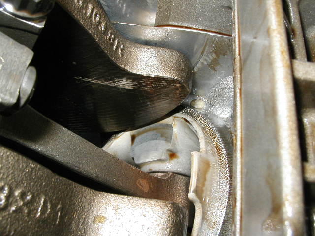
 Ok, this
had me puzzled as well. I did had heat to get that bolt off the
manifold (pics above) but i wouldnt think it could do this? The
gasket that sits around the Tstat was immaculate!?!? The oild
filler cap was blistered from the fire damage...but how this got
like this is yet another mystery! (update...aparantly all the
gaskets in here end up looking blistered like this after a short
time)
Ok, this
had me puzzled as well. I did had heat to get that bolt off the
manifold (pics above) but i wouldnt think it could do this? The
gasket that sits around the Tstat was immaculate!?!? The oild
filler cap was blistered from the fire damage...but how this got
like this is yet another mystery! (update...aparantly all the
gaskets in here end up looking blistered like this after a short
time)
 another
view of it....
another
view of it....
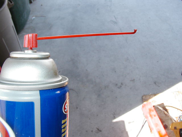
 my
modified carb cleaner nozzle : )
my
modified carb cleaner nozzle : )
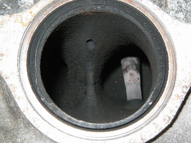
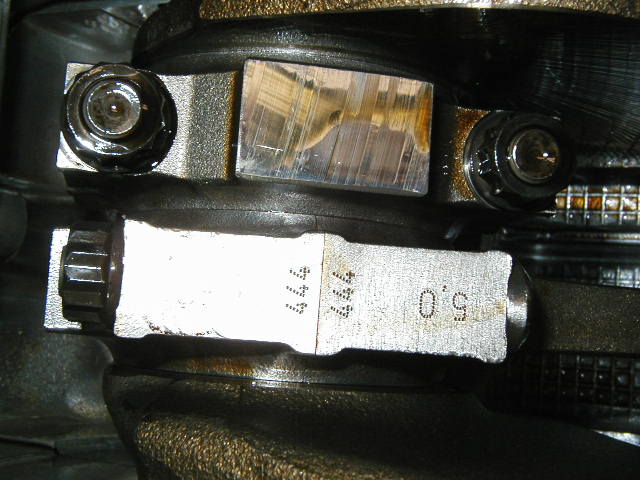
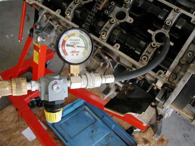
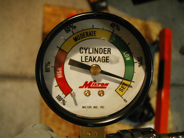
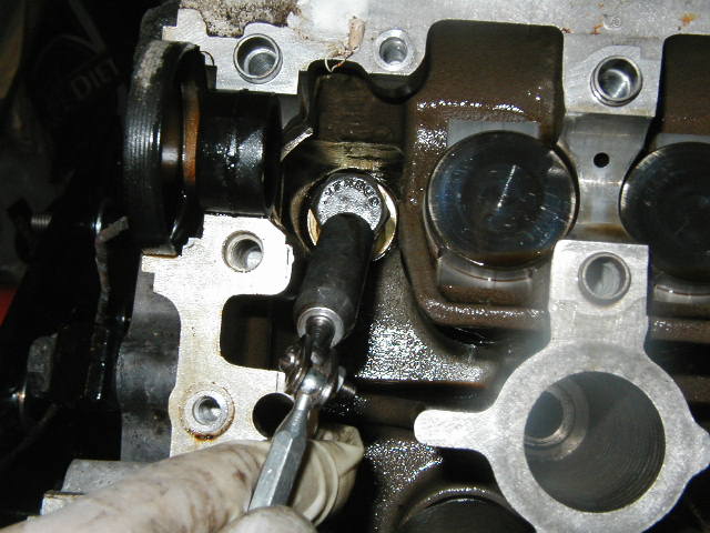
This is the leak down tester i got. I tried to get the one from Summit but its on back order until late October. Im not really up to speed on what to look for in a leak down tester but this one seemed pretty simple and worked great! No numbers to add...subtract...divide etc. It just gave me a ball park idea of what air was being kept in the cylinders. Referencing the picture below, the air source is coming in from the left via my compressor. It was regulated to 100psi. The line on the right goes into the spark plug hole. You start by hooking up your air source and with the yellow knob on the bottom abjust the needle until it reads "0" with the supplied pressure. If i were to remove the line going into the plug hole from the hole, the needle would swing to 100% meaning 100% of the air coming in, is also leaving. When i placed my thumb on the end of the line i could obviously change the amount of "leakage" and the gauge would reflect it instantly. Pretty simple and easy really.
The test should be performed on a warmed up engine. Obviously mine is on a stand and that isnt possible, but it still gave me some worth while information. this is what i did.
1)took an air hose and blew out the spark plug holes
2) removed the plugs
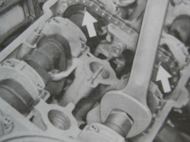
3) took the number 1 cyl to TDC via a wrench on the crankshaft and turning it CW.
4) Screw in the hose threaded for the plug hole.
5) calibrate the gauge
6) have some one hold the wrench on the crank so it doesnt try to trun with pressure applied. (thanks Bill)
7)connect the plug hose to the gauge then note the reading...listening at the intake port...exhaust port...and under the crankcase ( my oil pan was off) for any air escaping.
8) unhook the plug hose from the gauge and move on to the next one. The best way to do the test is in the firing order of the cylinders. When you go to the next cylinder, place a wooden dowl or a long screwdriver in the plug hole and again rotate the crank CW. Since the next cylinder is the next one to "fire" when the dowel or screw drive is fully extended out of the plug hole, that cylinder is at TDC on the compression stroke.
 #1
cylinder
#1
cylinder
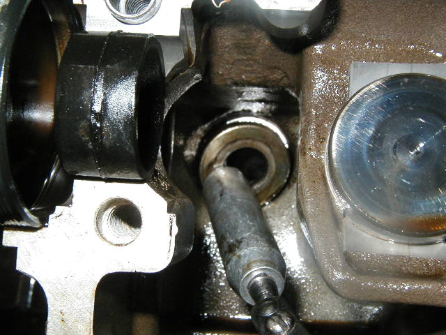
 ..at TDC
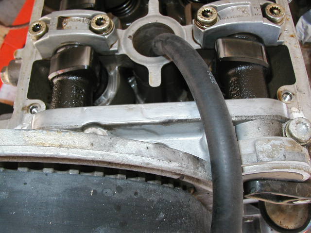 ...hose threaded
in spark plug
...hose threaded
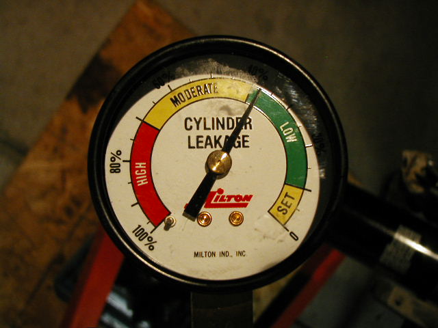
in spark plug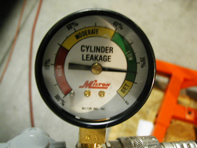 ...........#3
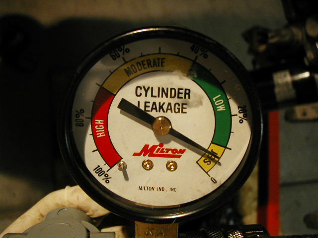 ..........#7 WOW!
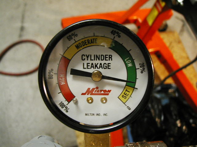 .........#2
 .............#6..ehhhh
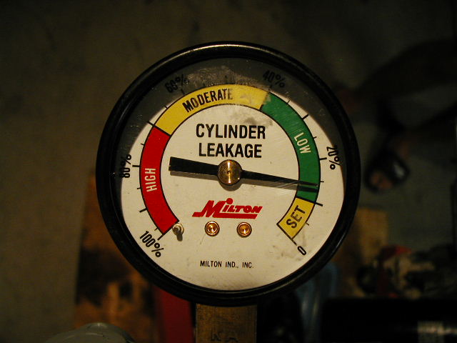 ...............#5
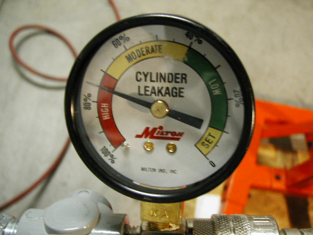 .............#4....UH
OH!!...(i later found a good deal of carbon and soot on the
intake valves..could have been the result of the fire and the
enigne runnign at the time)
.............#4....UH
OH!!...(i later found a good deal of carbon and soot on the
intake valves..could have been the result of the fire and the
enigne runnign at the time)
 .................#8
if any of you would like to borrow the gauge at some point let me know. 10 bucks and shipping, you can "borrow/rent" it : )
 ...not
much clearance either!
...not
much clearance either!
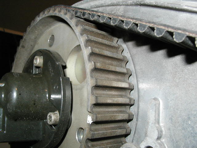 nice
"new" lookng cam sprocket!
nice
"new" lookng cam sprocket!
Wednesday 10-08-03
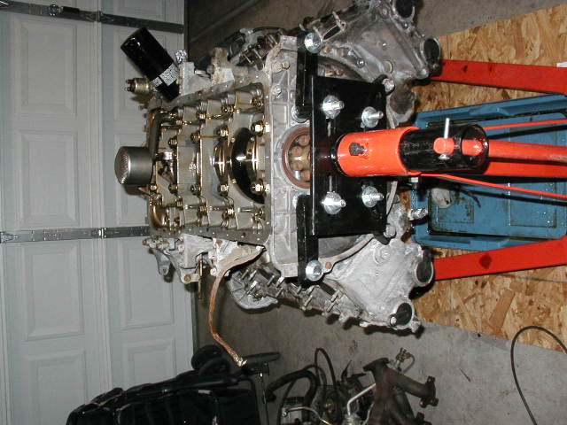
First major hurdle.
How do you remove a 200+ ftlb crank bolt when you know longer can attatch "the flywheel" tool....Hmmmmmmmm
A bit of head scratching and a trip to home depot and this is what i did.
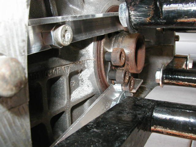
I bought some aluminum angle stock, cut it to length, drilled holes on center for a span from the flywheel bolts to the mounting bolts for the starter housing. I did this twice for added strength and placed the aluminum so the crank was either pushing or pulling directly on the aluminum length wise. I added some washers and a nut here and there to compensate for the depth of the various bolts. BEFORE YOU MEASURE THE DISTANCE OF THE HOLES...TURN THE CRANK TO 45'. This is where it needs to be locked in postion for belt removal.
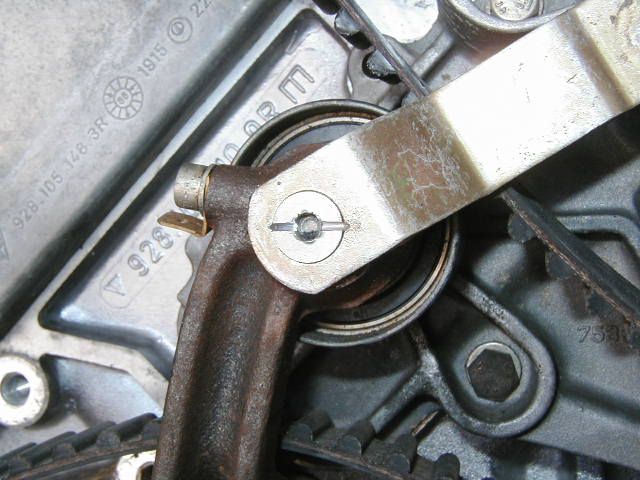
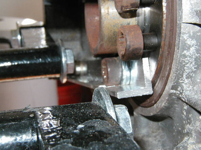 i did a
little dremel work here so the bolt and washers would sit flush
against the aluminum.
i did a
little dremel work here so the bolt and washers would sit flush
against the aluminum.
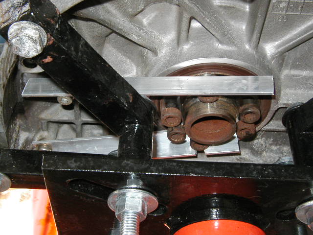 the
finshed product ready to be put to use.
the
finshed product ready to be put to use.
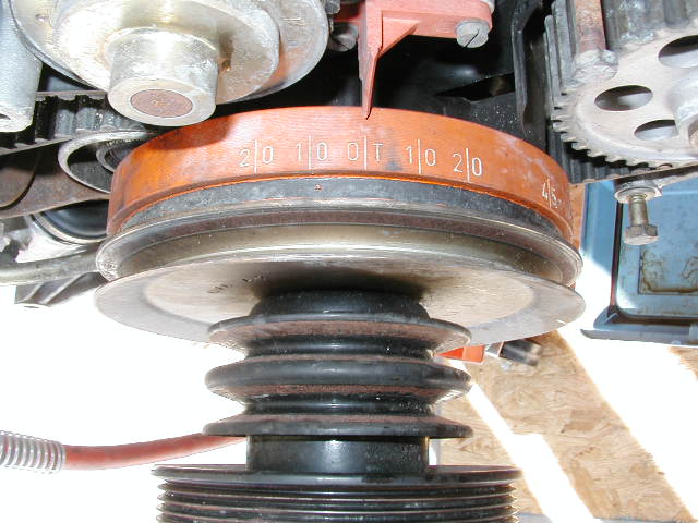
 ...oh...BIG
TIP!! like i said above, besure you put your crank at 45' before
you measure for the holes on the aluminum lock. Your taking all
this off so you can remove the belt, which is done at '45
...oh...BIG
TIP!! like i said above, besure you put your crank at 45' before
you measure for the holes on the aluminum lock. Your taking all
this off so you can remove the belt, which is done at '45
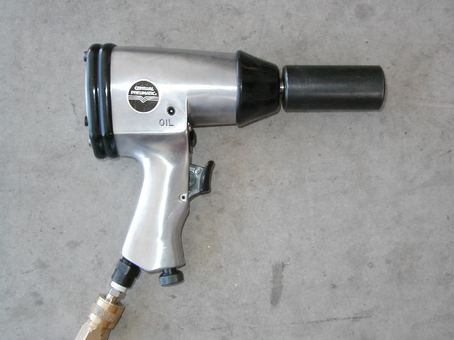 ..ah..yes...the
weapon of choice for the crank bolt. I will not be defeated or
suffer from scraped knuckles this time! A couple hundred pds of
Tq and a "chattering" impact action as well. With the
setting on 4 out of 4 i let her rip...KLAK KLAK KLAK
KLAK..BzzzzzzzzzzzzzzzzzzSHHHHHHHHHhhhhhhhhhhhhhhhhhhhhh the bolt
unthreaded effortlessly. For a reference i couldnt get it to
budge using my hand wrench and 4 ft breaker bar...the engine
stand was a pain to keep still as well! The gun was almost
instant, and the stand did not move an inch!
..ah..yes...the
weapon of choice for the crank bolt. I will not be defeated or
suffer from scraped knuckles this time! A couple hundred pds of
Tq and a "chattering" impact action as well. With the
setting on 4 out of 4 i let her rip...KLAK KLAK KLAK
KLAK..BzzzzzzzzzzzzzzzzzzSHHHHHHHHHhhhhhhhhhhhhhhhhhhhhh the bolt
unthreaded effortlessly. For a reference i couldnt get it to
budge using my hand wrench and 4 ft breaker bar...the engine
stand was a pain to keep still as well! The gun was almost
instant, and the stand did not move an inch!
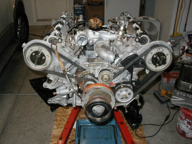
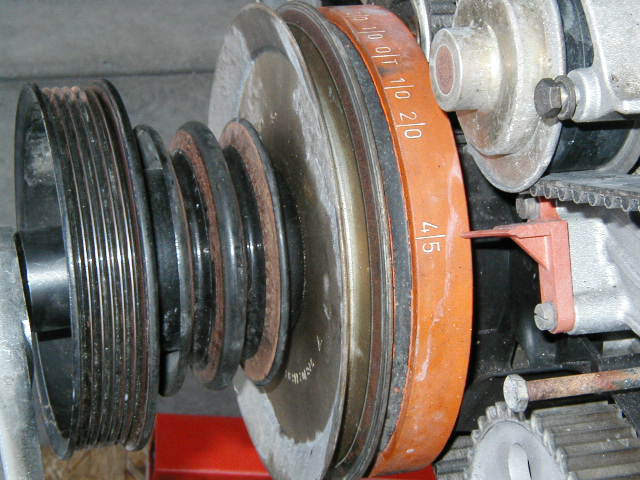
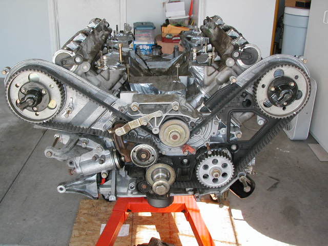
 pulleys
removed!..T belt system next. All locked at 45'
pulleys
removed!..T belt system next. All locked at 45'
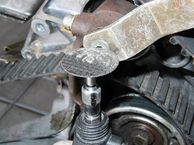
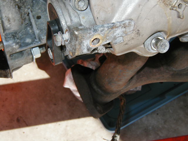
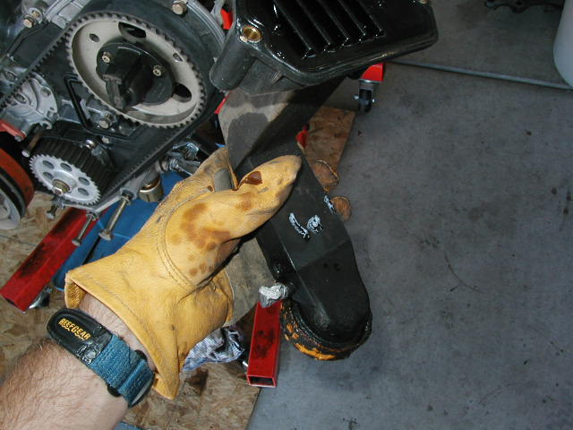
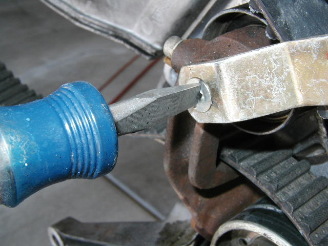
 ...ah..this
little SOB! of coursse the darn thing was almost rounded out to
begin with. It was stuck, not going to move. Teh Hex head just
got more round and round with each attempt. The solution after a
beer and soem head scratching. THE DREMEL TOOL! If you daont have
one, get one! I place the large cuttign bit on and notched the
bolt as seen above. I put a wide, flat blade screw driver on
it....Presto...no effort at all and it was off!
...ah..this
little SOB! of coursse the darn thing was almost rounded out to
begin with. It was stuck, not going to move. Teh Hex head just
got more round and round with each attempt. The solution after a
beer and soem head scratching. THE DREMEL TOOL! If you daont have
one, get one! I place the large cuttign bit on and notched the
bolt as seen above. I put a wide, flat blade screw driver on
it....Presto...no effort at all and it was off!
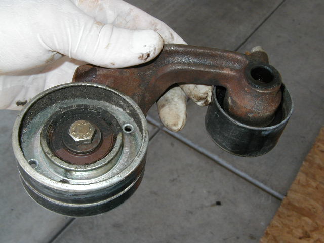 all the
bushings looked great..no play at all...none of them cracked or
damaged...pulleys spun freely
all the
bushings looked great..no play at all...none of them cracked or
damaged...pulleys spun freely
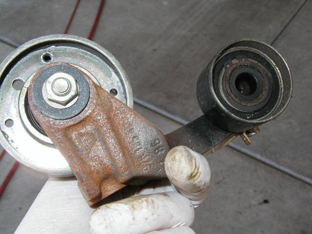
 ...it even
had oil in the tensioner!! The boot looked good as well.
...it even
had oil in the tensioner!! The boot looked good as well.
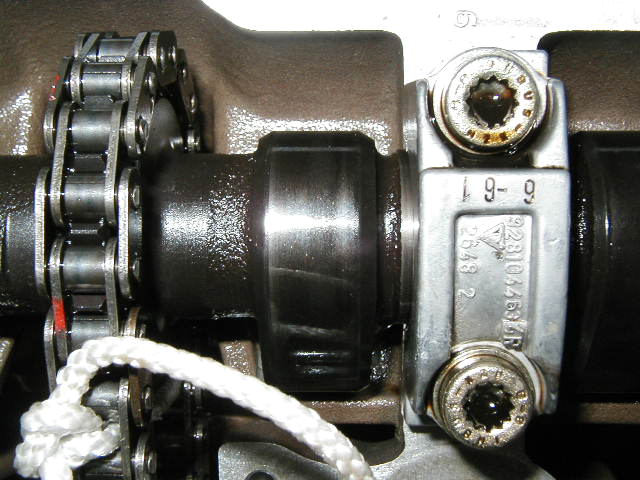
 apicture
from the shop manual refering to the marks on the cams that need
to be place vertically before removal. Of course i couldnt find
them. I just had little triangular nubs cast intot he cams as
seen below. A quick call and an email to Mark and Jim at www.928intl.com confirmed that
some of the cams didnt have marks on them and the casting
"nubs" were what should be used.
apicture
from the shop manual refering to the marks on the cams that need
to be place vertically before removal. Of course i couldnt find
them. I just had little triangular nubs cast intot he cams as
seen below. A quick call and an email to Mark and Jim at www.928intl.com confirmed that
some of the cams didnt have marks on them and the casting
"nubs" were what should be used.
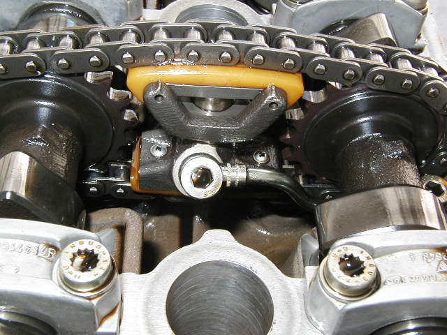 ..the
"nubs" on the cams pointing up.
..the
"nubs" on the cams pointing up.
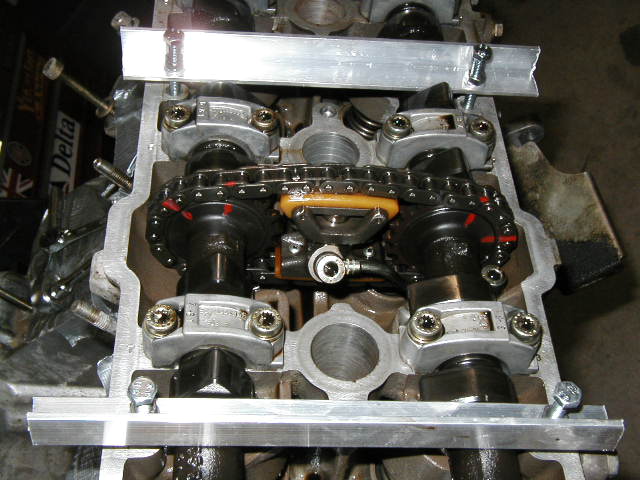 with the
cams in postion for removal i marked and scribed there positions.
Mark Anderson then gave me antoher good idea to keep the exhasut
and intake cam in the same position to one another after removal.
Secure the chains with a tie wrap or something....I used some
string...see below! It worked great!!
with the
cams in postion for removal i marked and scribed there positions.
Mark Anderson then gave me antoher good idea to keep the exhasut
and intake cam in the same position to one another after removal.
Secure the chains with a tie wrap or something....I used some
string...see below! It worked great!!
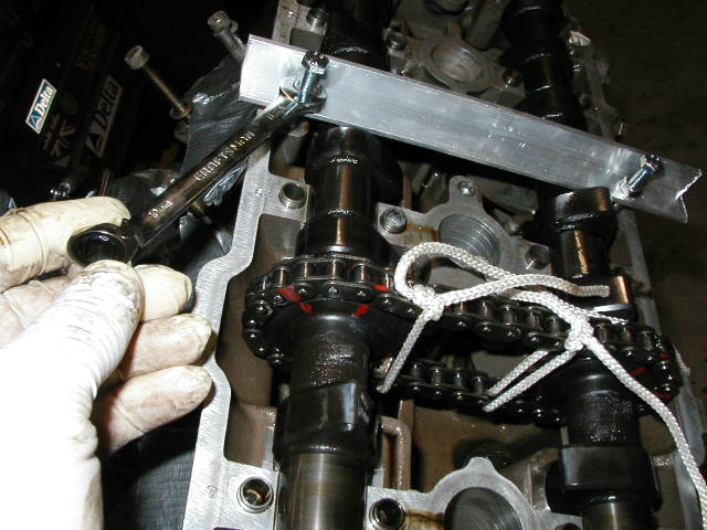
Above you can also see my cam removal tool i made. Some more aluminum stock with two holes drilled on 158 mm center (check your own application) I got some longer bolts to thread in to the head and a set of nuts and washers to snug the tool down on the cam. With the tool holding the cam i removed all the Star bolts from the cam holders. Non of them stripped or were tight, then again i was using the same "chatter gun" i used onthe crank bolt...but at a lower setting. It made VERY quick and short work of the removal process.
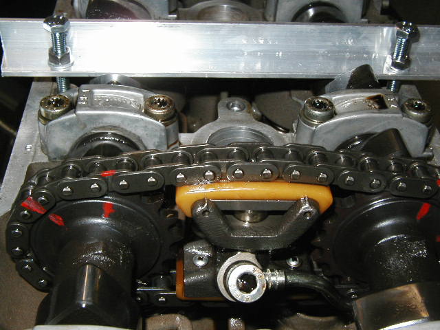
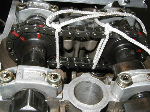 ...the
string trick i used to keep the cams in the same psotion relative
to one another.
...the
string trick i used to keep the cams in the same psotion relative
to one another.
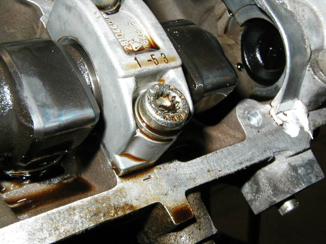
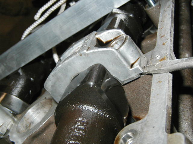
 ...screw
driver gently lifting the cam bridge.
...screw
driver gently lifting the cam bridge.
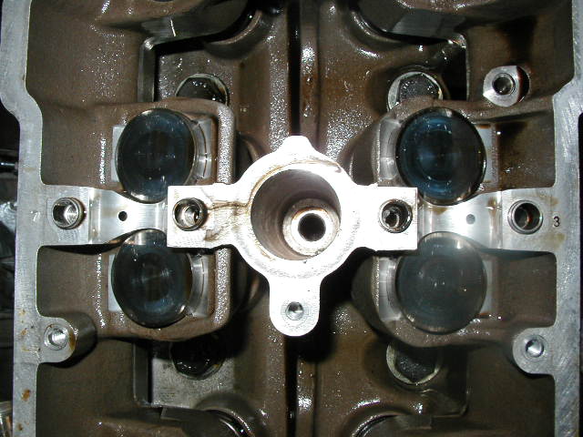
 ..these
are the infamous camshaft plugs that sit at the end of the
shorter 87+ cams. The plug the oil passage that would normally
ffed the cam at that location. Occaisionally they will be come
dislodged which may be indicated by a lower than normal oil
pressure when idling (theres not restriction on the flow of oil)
The replacement part for these now are small aluminum pins.
..these
are the infamous camshaft plugs that sit at the end of the
shorter 87+ cams. The plug the oil passage that would normally
ffed the cam at that location. Occaisionally they will be come
dislodged which may be indicated by a lower than normal oil
pressure when idling (theres not restriction on the flow of oil)
The replacement part for these now are small aluminum pins.
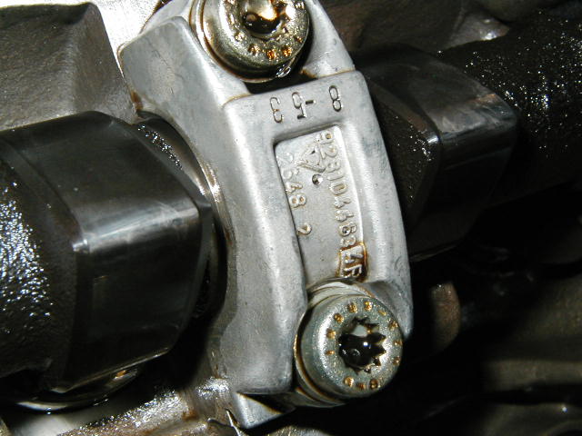
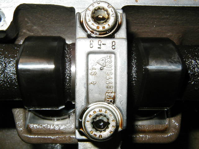
 with all
the bolts removed and my tool holding the cams down i removed all
the cam retainers. A very gentle soft lift with a screw driver
under the povided lip works them free. Be careful not to damage
the valve cover gasket seat on the head. These parts are numbered
so for piece of mind i recorded there locations.
with all
the bolts removed and my tool holding the cams down i removed all
the cam retainers. A very gentle soft lift with a screw driver
under the povided lip works them free. Be careful not to damage
the valve cover gasket seat on the head. These parts are numbered
so for piece of mind i recorded there locations.
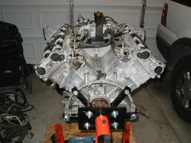
 The VEE
is good for something! A parts tray holder..and..a TwinScrew SC
intercooler : ) Hmmmmmm.
The VEE
is good for something! A parts tray holder..and..a TwinScrew SC
intercooler : ) Hmmmmmm.
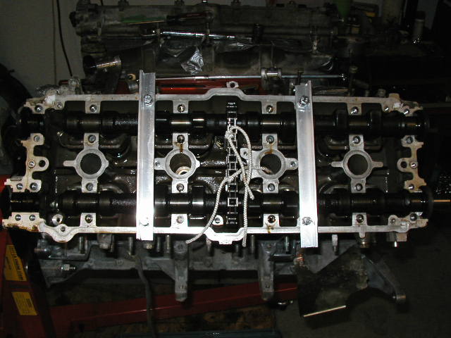 heres a
shot with it all off excpet my home made cam holders.
heres a
shot with it all off excpet my home made cam holders.
 ..now it
was a matter of just backing off the bolts sequentialy...a bit at
a time. I found that there really isnt much force holding them in
there. I had illusions of them trying to spring out like a
tightly coiled snake! Not the case. this little tool worked
great! If i can get a video loaded i will show you how quick and
effortless this step was! Installing may be a different story : )
..now it
was a matter of just backing off the bolts sequentialy...a bit at
a time. I found that there really isnt much force holding them in
there. I had illusions of them trying to spring out like a
tightly coiled snake! Not the case. this little tool worked
great! If i can get a video loaded i will show you how quick and
effortless this step was! Installing may be a different story : )
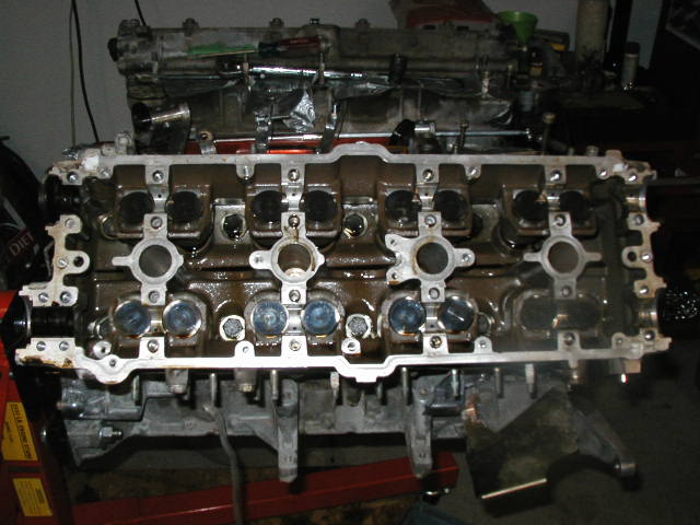 ..tah da!!
 ..the
cams, string intact, holding there postion to one another.
..the
cams, string intact, holding there postion to one another.
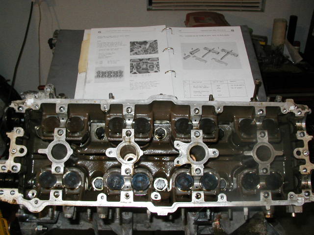 ...now for
the head!! I placed the shop manual in the VEE as a reference.
This is important because there is a special sequence to the
removal of the bolts as well as installation. Installation is
...now for
the head!! I placed the shop manual in the VEE as a reference.
This is important because there is a special sequence to the
removal of the bolts as well as installation. Installation is
1) 1st stage...15ftlbs
2) 2nd stage...90' of turn
3) 3rd stage...90 of turn
.....all done in the pattern shown in the manual.
Removal per the manual says" reverse order", thats it...typical
Really an uneventfull process. They sure are snug to begin with though! Not a job id like to do with the engine in the car!
 ....using
the magnetic tool to pull out the bolt and washer.
....using
the magnetic tool to pull out the bolt and washer.
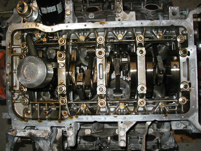
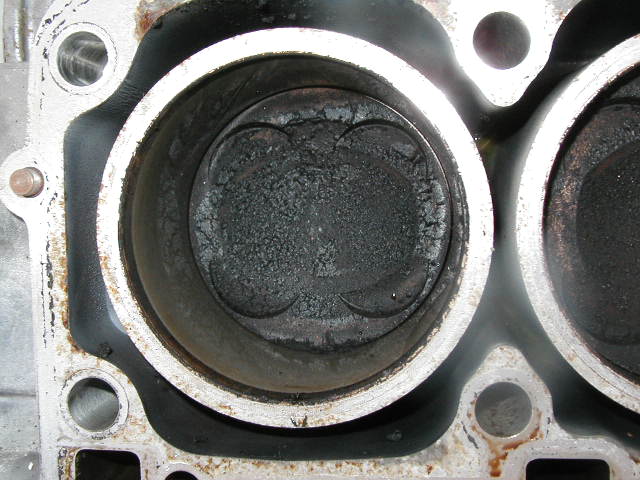
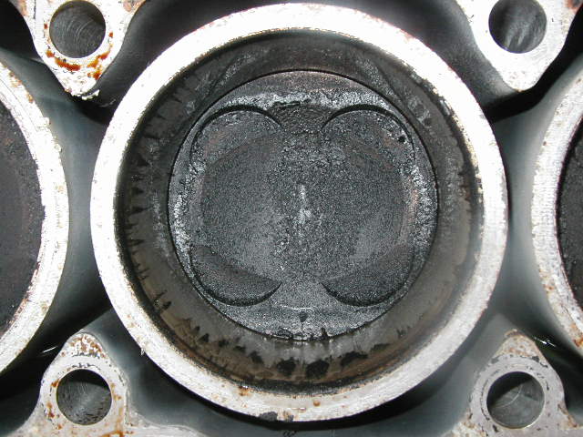
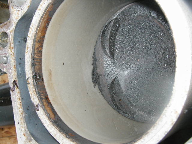
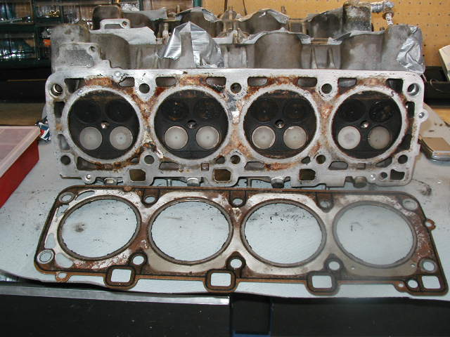
Using a block of wood between the hammer and the head, i gentle gave the head a tap upwards around all 4 corners. The head broke loose pretty easily and i lifted it off...the gasket stuck a little in a few palces but eventually separated. Below is what the psitons/clyinders looked like.
again...a 37k car (so they said) with a fuel rail fire or the likes, near the aft part of the engine bay.
 .....#1
 ....#2
 .....#3
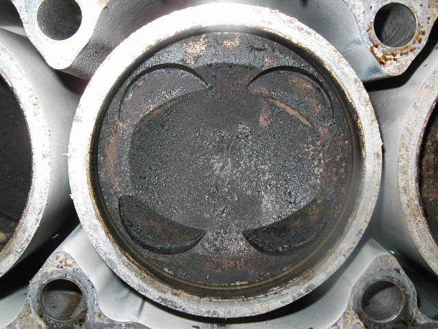
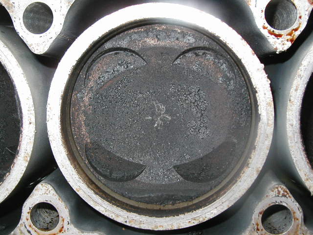
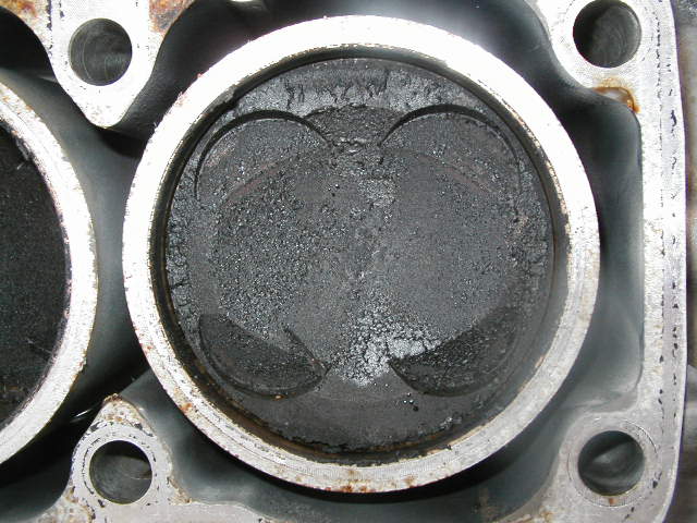
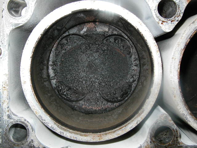 ......#4..nasty
HUH! i think all that black stuff, besides being a bit of carbon,
is soot and smoke debris?? anyone? I thought it looked a Weeeeeee
bit heavy.
......#4..nasty
HUH! i think all that black stuff, besides being a bit of carbon,
is soot and smoke debris?? anyone? I thought it looked a Weeeeeee
bit heavy.
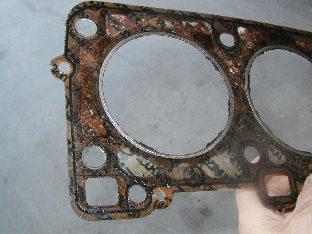
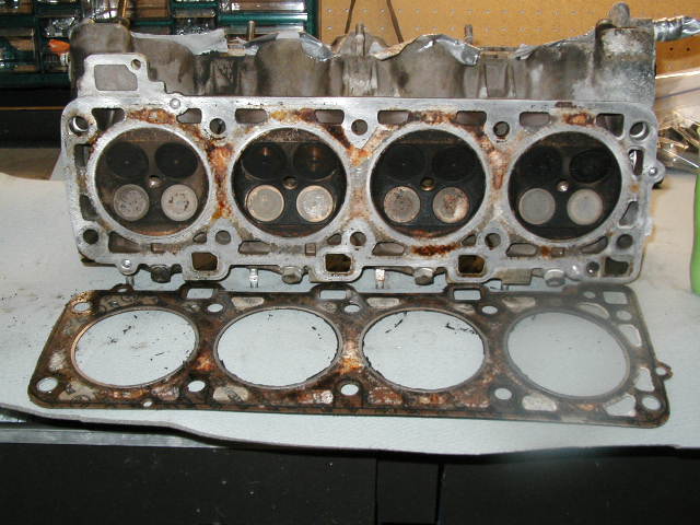 #1...2...3...4
and the gasket mating surface
#1...2...3...4
and the gasket mating surface
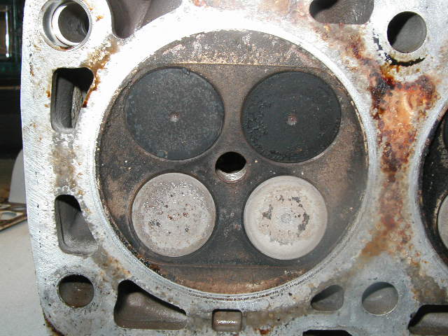 ...#1 head
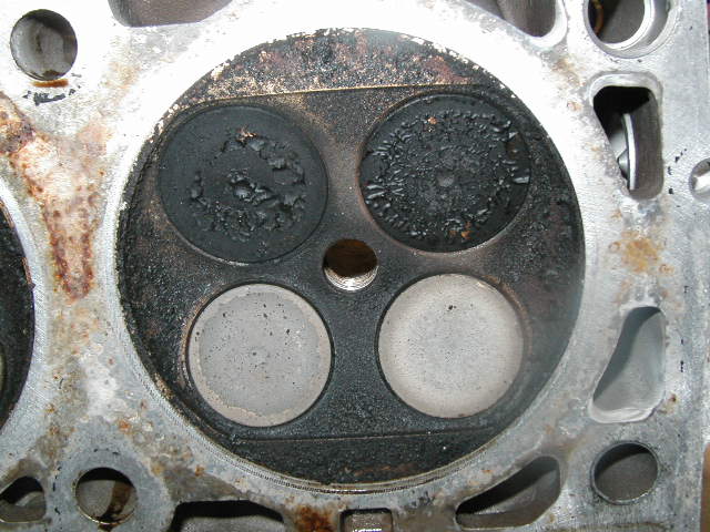
 ....#2
 .....#3
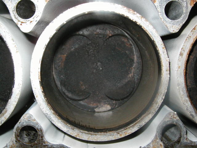
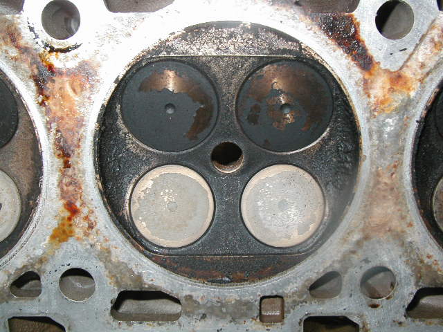
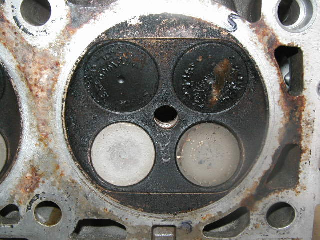
 ....#4
again, looking at #4 cylinder above the same residue is on the
valves. If i blew hard enough it comes off. Scrapes easy with the
nail and is VERY soft, thankfully! Not a mark on the cyl walls
where i can see!
....#4
again, looking at #4 cylinder above the same residue is on the
valves. If i blew hard enough it comes off. Scrapes easy with the
nail and is VERY soft, thankfully! Not a mark on the cyl walls
where i can see!
Thursday 10-09-03....driver side head comes off
 ....#5
 ....#6
 .....#7
 #8
#8
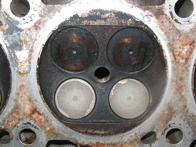
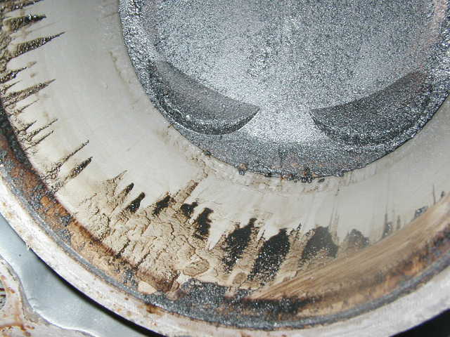 ....#7.....the
streaks are from the cleaner i used in the intake
ports...obviously they didnt seal 100%. Looking at all this why
be suprised huh!
....#7.....the
streaks are from the cleaner i used in the intake
ports...obviously they didnt seal 100%. Looking at all this why
be suprised huh!
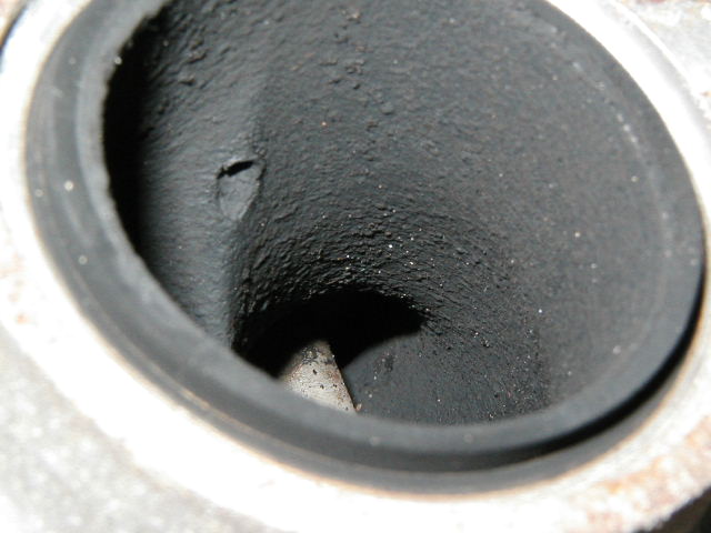
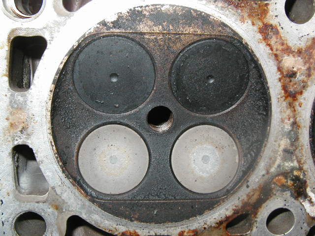
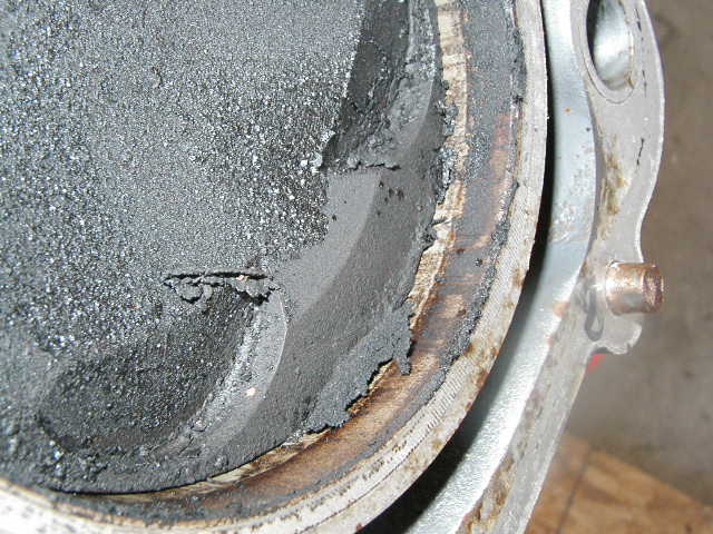 ...#8...Nnnnnasty
looking isnt it!. this stuff is very soft and brittle...if i were
to blow on this it would fly off. . My next objective is to vac.
all this out and clean up the cylinders and check for any damge
this all may have done in areas i ahvent seen yet.
...#8...Nnnnnasty
looking isnt it!. this stuff is very soft and brittle...if i were
to blow on this it would fly off. . My next objective is to vac.
all this out and clean up the cylinders and check for any damge
this all may have done in areas i ahvent seen yet.
 as labled
with my marker...#5
as labled
with my marker...#5
 ....#6
 ....#7
 ...5..6..7..8
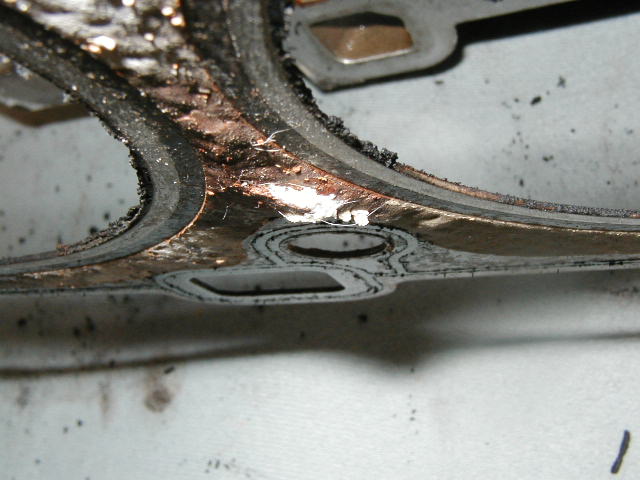
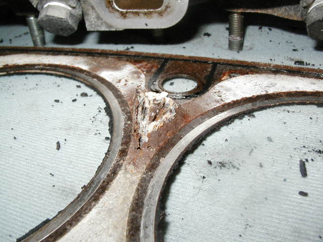 ..UH OH!
this area was stuck to the head. Its bulged like that becasue it
was stuck when removed...still not good though! see below!
..UH OH!
this area was stuck to the head. Its bulged like that becasue it
was stuck when removed...still not good though! see below!
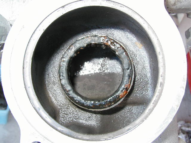
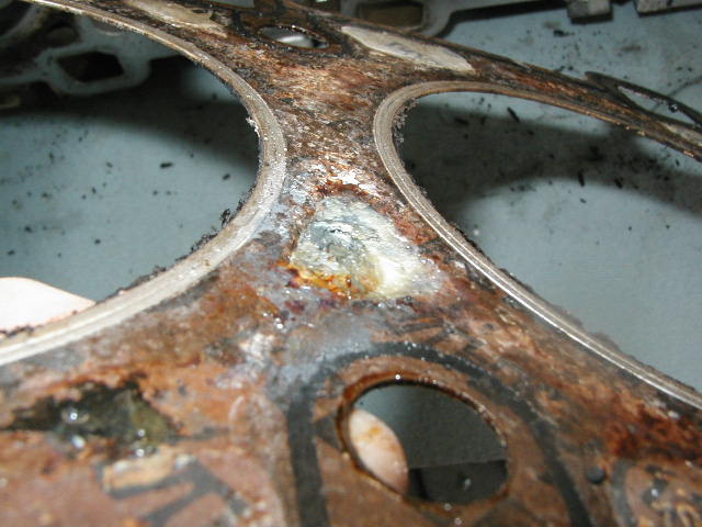
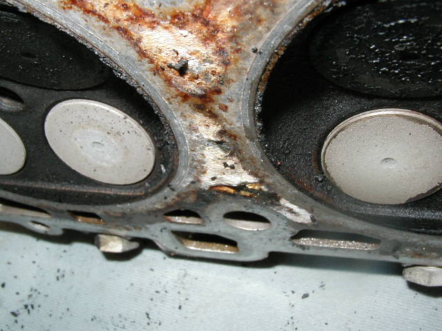
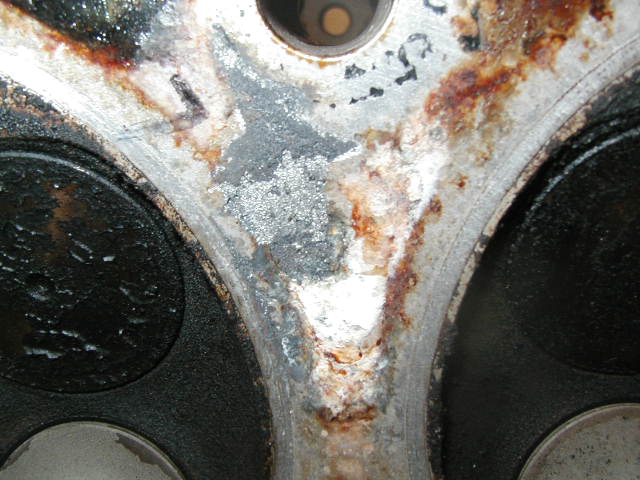 there area
here corresponds to the head gasket condiotn above. Definitley
some pitting/ corrosion of some sort...caused by
something...ANYONE??? (update 2-4-04...im going to have these
areas of corrosion welded up then the heads resurface per the
shop manual spec) Since im running boost i want NO ISSUES with
cylinder head mating.
there area
here corresponds to the head gasket condiotn above. Definitley
some pitting/ corrosion of some sort...caused by
something...ANYONE??? (update 2-4-04...im going to have these
areas of corrosion welded up then the heads resurface per the
shop manual spec) Since im running boost i want NO ISSUES with
cylinder head mating.
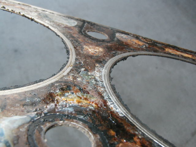
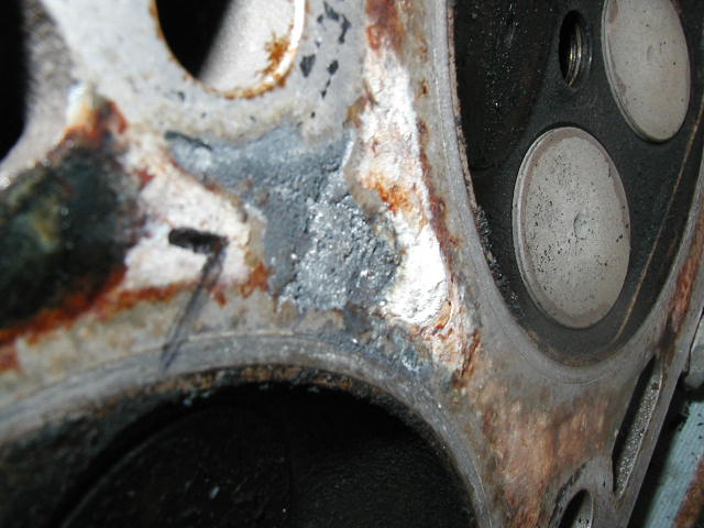 ...and
angled shot. its not that deep but none the less it aint
smooth!!!
...and
angled shot. its not that deep but none the less it aint
smooth!!!
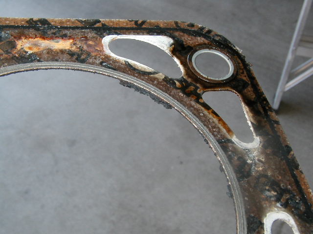
 ..more of
the same area on the gasket
..more of
the same area on the gasket
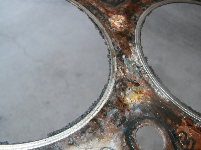
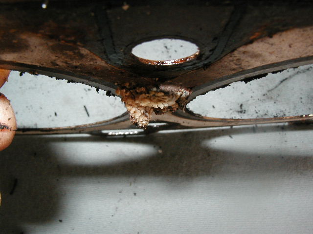 pretty
dramatic huh! this was the area stuck to the head. It separated
fine but none the less was stuck, which is the reason for the
dramatic looking damage
pretty
dramatic huh! this was the area stuck to the head. It separated
fine but none the less was stuck, which is the reason for the
dramatic looking damage
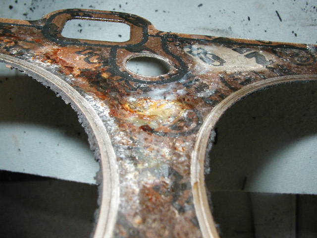 ...not
here also the black deposits around the head gasket ring.
...not
here also the black deposits around the head gasket ring.
wed 10-15-03
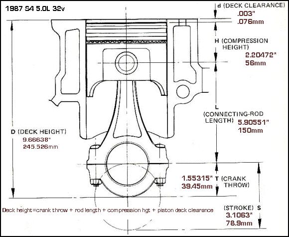
For my own curiosty and to get a number ill probably need for future calculations i spent today finding the piston deck height. The clearnace between the top of the piston and the cyl/block deck. It isnt much.
I started by cleaning the part of the piston and block id be measuring. Any carbon or gasket material left will change the results. It doesnt take much.
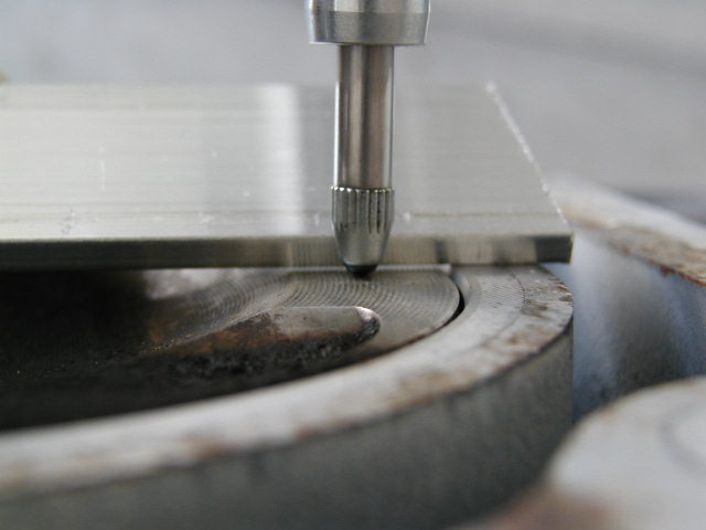
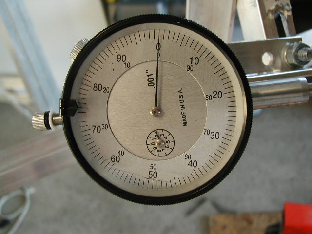
I then found TDC. It can be "eyeballed" but the dial indicator makes it so much easier. I bought an indicator and fabricated my own stand for it. The handy magentic stand is pretty useless on our engines. I got the dial positioned over the piston pin axis, 90 vertical to the block and rotated the crank until the needle stopped moving. Id adjust the outside bezel a bit so the needle would sit on one of the marks, for easier reference...then id do it again. I did this a couple of times to besure i had it spot on.
Next step was to get a good flat piece of metal. I had some aluminum stock and i cut it to length so the ends only sat on the cylinder i was measuring.
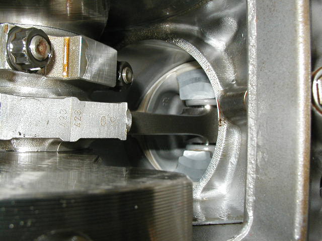
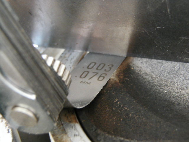
I took the metal and sat it on top of the cylinder along the piston pin axis. Im pretty sure thats the way to measure the clearance as no piston rock is induce. With the metal in place, i took my flash light and placed it behind the metal. The gap between the piston and metal edge stuck out like a sore thumb!
next it was a matter of sliding feeler gauges under the metal as i held it in place.
.003in worked...... .004 didnt actaully if you were to get really picky id say it was actaully .0035 but the feeler guages dont go that thin.
so i figure the piston deck clearance is .003in. (.076mm)
Does ths sound correct to you all? sure isnt much is it!!
pics of the process below.
 ....my
dial gage rig held everything tightly in place and worked very
well.!
....my
dial gage rig held everything tightly in place and worked very
well.!
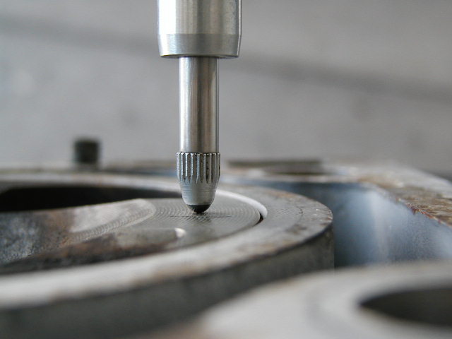 ....a
close up so you can see how important it is to get the surfaces
used for measuring clean.
....a
close up so you can see how important it is to get the surfaces
used for measuring clean.
 .....pay
no attention to the value displayed on the indicator as i
adjusted the bezel to make it easier to see the piston hit TDC.
...it stopped right on that line. Turn the crank ANY more and it
moves off that line.
.....pay
no attention to the value displayed on the indicator as i
adjusted the bezel to make it easier to see the piston hit TDC.
...it stopped right on that line. Turn the crank ANY more and it
moves off that line.
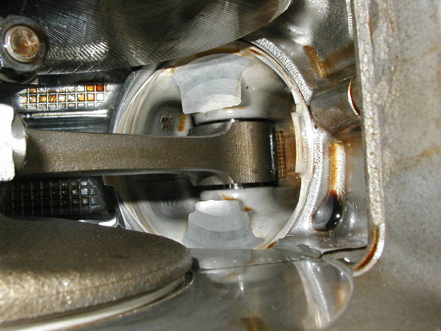
 piston at
TDC and my flat piece of metal set down on top of the cylinder.
Makes it easy to see the clearance involved doesnt it!.
piston at
TDC and my flat piece of metal set down on top of the cylinder.
Makes it easy to see the clearance involved doesnt it!.
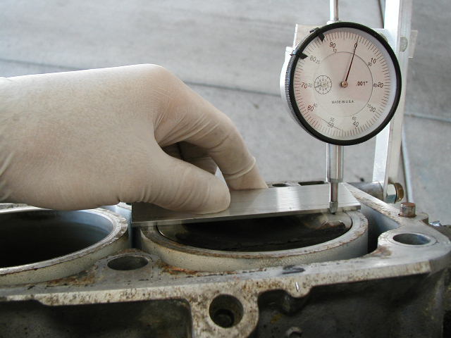 ...basically
the big picture of what i did.
...basically
the big picture of what i did.
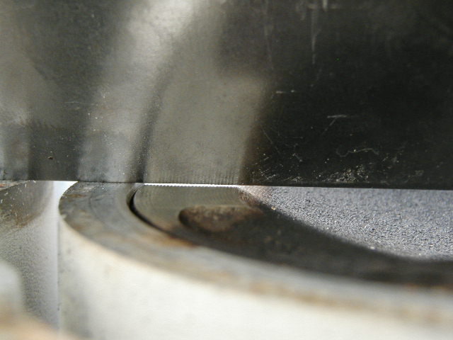 ...the
clearance is easily shown with the light behind it!
...the
clearance is easily shown with the light behind it!
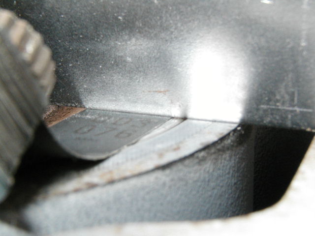
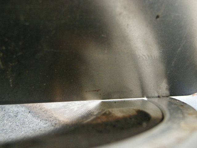 ..this is
the other side.
..this is
the other side.
 ...now it
was a matter of sliding different feeler gages
underneath......007 nope, .005 nope...... .004 nope .........
.003 perrrrrfect. ..... .002 nope, way to loose. back and try
them again. Same result.
...now it
was a matter of sliding different feeler gages
underneath......007 nope, .005 nope...... .004 nope .........
.003 perrrrrfect. ..... .002 nope, way to loose. back and try
them again. Same result.
 ..i then
did the same thing on the other side. .003 it was!
..i then
did the same thing on the other side. .003 it was!
So...what does this say? the clearance between the top of the piston and the cylinder wall/block is .003" or .076mm
all the numbers i know.....................
head gasket dia of 4.020 inches or 102.108mm (10.2108cm) (fire ring)
head gasket thickness (fire ring) .042 inches...or....1.066mm.... .1066cm (this gasket was crushed, but measured in an uncrushed state)
head gasket volume: 7.57 cc (thnx Jay for the higher math)
combustion chamber volume(per someone elses notes) : 42cc (update 2-04-04...mine cc'd at 40)
S4 piston volume (per someone elses notes): 24cc (updated 2-4-04..mine cc'd at 24....being machined to 30cc for lower CR)
I plan on getting my own volumes eventually, just for the sake of learning how to do it.
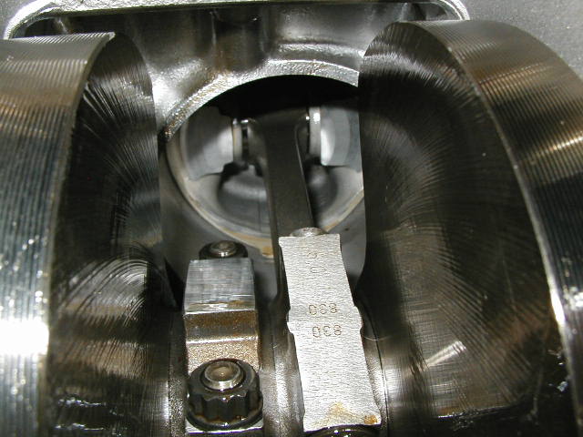
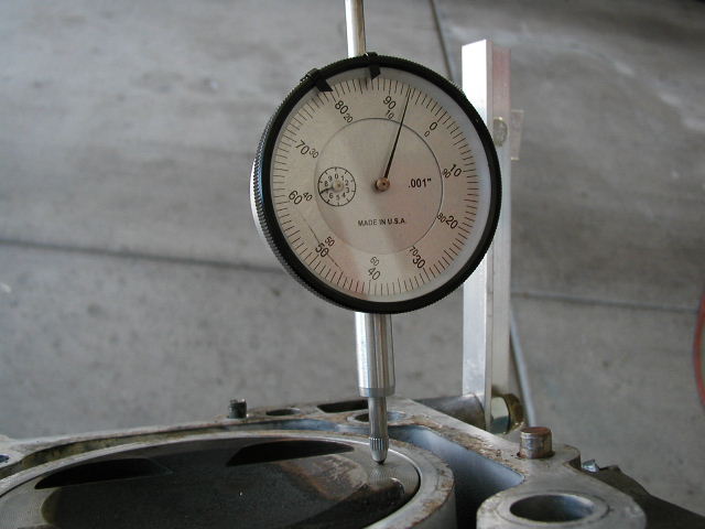
With my dial gauge and rigged stand (quite the contraption huh!! )i set about to measure the thrust bearing. I got the stand mounted and the indicator in postion. I pushed the crank back into the block by prying it from the flywheel end. I then zeroed out the dial gauge and pushed the crank forward. The indicator shows the value. .00575 appx. .Looks good! i did this several times with the same result. The engine has 37,000 miles on it.
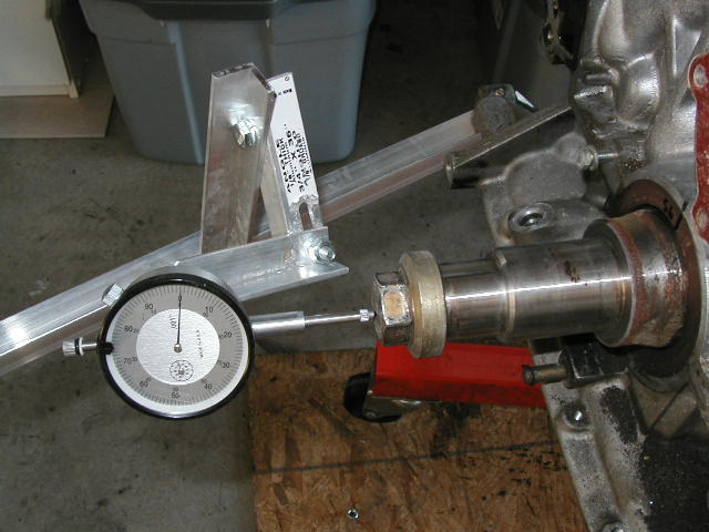 rigged up
stand and indicator pusing on crank bolt.
rigged up
stand and indicator pusing on crank bolt.
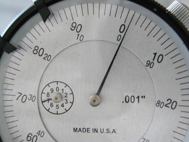
 ...zeroed
out to start...
...zeroed
out to start...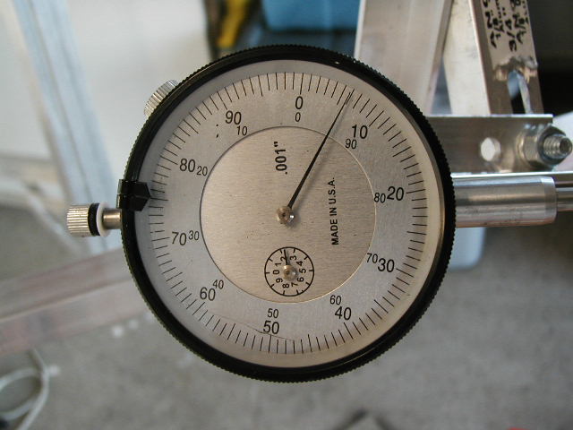 ...crank shaft pushed fwd with this amount of
movement.
...crank shaft pushed fwd with this amount of
movement.
Looks like .00575 to me. Well in the middle of the specs which are .0024" to .0076". Wear limit is .016"
....And no grief about the grammar and spelling. I dont have a spell checker and its often late when im doing all this stuff....and its a few beers later : ) Ill get to the nitty grittys of the page later
Anyway....Please, if any of you have any comments, or inptu on what you see, let me know! I value allof your input!
cheers!
Update as of 2-4-04
I need to upload the rest of the pics i have but at the current time the block is in half...crank removed...pistons are out and separated from the roads. In simple terms, there is nothing else i can take apart! the pistons are at the shop being machined to 30ccs. The heads have all the valves removed and all the valve guides appear to be in good shape, keeping the valves in spec. The heads will go off to be cleaned up..resurfaced..and MAYBE ported. Im not sure about that yet as i really dont want to deal with the removel of 32 valve guides and seals. With a supercharged application porting isnt going to give me much in the HP, i dotn think its worth the added cost or effort at this point.
Next.... order new rod bearings...crank bearings...rings..and gaskets and start bolting this thing back together. The hard and time consuming part!
Thanks to all the guys at the RENNLIST FORUM and to Mark and Jim at the link below for all there help when i have questions. Mechanically speaking this is the BIGGEST thing i have attempted in my life!! Will it last??? dunno...sure would be nice! But im not going to get wrpped around the axel worrying about it. So far its been a great education, challange and honeslty, most of all, FUN. I enjoy heading out to the garage, turning on the tunes and spending part of an afternoon or late evening working on it.
