1986 951 Zeitronix
Wideband Installation
Copyright © 2004, Tom M’Guinness
This document can be freely copied
in its original
form,
for non-commercial purposes only.
All other rights reserved.
These
instructions are based on my own installation of the Zeitronix
wideband in my 1986 944 turbo. I installed the wideband, Zt-2 and boost gauge,
but not the exhaust gas temperature (EGT) sensor.
Install
O2 Bung. The
first step is to get the O2 sensor bung installed. The wideband bung needs to
be installed after the turbo and before the catalytic converter. It also needs to be installed so the tip is
pointing downward. I opted to install it
in my test pipe, where it tucks up nicely behind the starter. With the test
pipe in the car, I took a magic marker and marked a big dot where the bung and
O2 would fit well. I then took the test
pipe to my local Midas shop, and they welded the bung in for free in about 10
minutes.
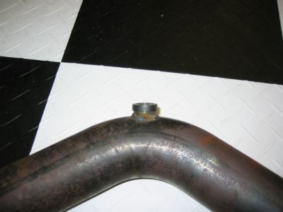
This is how the bung looks
installed in the test-pipe.
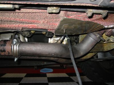
And
here is the test-pipe and sensor installed in the car.
Install
O2 Harness. I pushed the O2 sensor (phone jack end) into a
pre-existing hole in the bulkhead wall into the battery area. Then I stuffed the wire into the passenger
compartment through the firewall hole behind the battery. It takes some work to get the cable out from
behind the glove box, but if you work at it, you can get the cable to route out
behind the glove box.
On the end
of the harness with the big O2 harness connector, if you installed the bung
where I did, you are best off routing the harness wire down the passenger side
of the firewall above the bell housing.
Letting it dive down near the Co2 sample tube. Remember that the O2 sensor itself has about
2 feet of heat-resistant cable, so the big connector only needs to drop down to
about the top of the bell housing. Route
the wires away from the headers and exhaust pipes.
12-Wire Zt-2 Connector. This connector
looks like a pain to install, but there is actually not much involved. There are really three sets of wires. Two wires get spliced into the
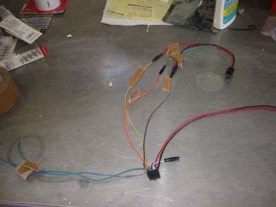
Here is how I connected the wires
from the 12-pin connector
Wire 1 (red): connects to
Wire 2 – not used
Wire 3 (green): connects to
Wire 4 (orange): connects to boost sensor’s green wire
Wire 5 – not used
Wire 6 (yellow) connects to boost sensor’s red wire
Wire 7 (black) connects to
Wire 8 (brown) connects to boost sensor’s black wire
Wire 9 – not used
Wire 10 (grey) connects to KLR pin 22 (white/green, TPS)
Wire 11 – not used
Wire 12 (blue) spare input I connected to MAF
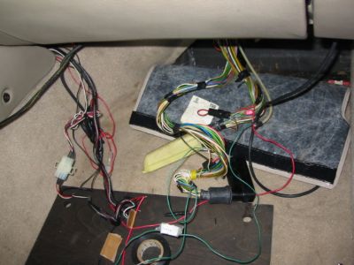
It’s not pretty in there, but once
you are done, no one will ever know.
Before
tapping any wires, be sure to disconnect the battery negative cable, and remove
the harnesses from the
Boost
Sensor.
The small boost sensor needs to be close enough to the Zt-2 for its
harness to reach. I ended up putting a T
in the line to my aftermarket boost gauge and tie-wrapped the sensor to the
underside of my glove box. I tucked the
Zt-2 behind the carpet on the passenger side transmission tunnel, so the
display and data-logging wires can run easily to the passenger seat (to connect
the laptop) or to the center console (for the display). I opted not to install the display
permanently. m
I had
no problem using the Zeitronix software on my Windows
XP laptop. The only glitch is that my laptop does not have a 9 pin serial
port. I solved that problem by buying a