1986 Porsche 951 Head Gasket Replacement (Rev. 1.0)
Copyright © 2006, Tom M’Guinness
All rights reserved.
IMPORTANT: The information on this page is believed to be correct, but please understand that the author does not accept any liability for any errors or omissions, and shall in no event be liable for damages in connection with this information based on any theory of law. Working on automobiles can be dangerous and should only be undertaken by those with the training, equipment, and ability to do so safely. The author disclaims all representations and warranties, express or implied, regarding the information provided on this website, including without limitation any implied warranties of FITNESS FOR PURPOSE or MERCHANTABILITY.
INTRODUCTION
There's an old joke: "how do you beat a 944 turbo? Wait for it to blow a head gasket and then fly right by." Head gasket failures are a fact of life with the 944 turbo, especially on modified cars. Replacing the head gasket is a relatively big project for the do-it-yourselfer. These instruction provide a guide and checklist to help organize the job, but they assume a certain level of familiarity and experience working on the 944 turbo motor, such as how to re-tension the timing belt. If nothing else, these instructions should give a fairly accurate description of the process and some of the problems likely to arise, so that the do-it-yourselfer can have a good sense (before tearing the motor apart) whether this is a job within his or her reach.
DIAGNOSING HEAD GASKET FAILURE
It's not always easy to tell when the head gasket it leaking. The symptoms are not always obvious, and can often mimic other (easier to fix) problems, such as blown oil seals, coolant leaks, vacuum leaks, etc. It often starts as a subtle problem, making it difficult to spot a bad head gasket at first. As the problem progresses, however, the symptoms can accumulate and leave little doubt. Careful attention to the car's symptoms, supplemented with testing as needed, can usually pinpoint a leaking head gasket. The most common symptoms and tests are:
Cooling System Problems. The head gasket forms the only barrier between the top of the cylinder and the water jackets surrounding the cylinders. When the head gasket leaks, combustion pressures escape into the water jackets. This creates air pockets in the cooling system and the same erratic cooling symptoms as a cooling system that needs to be vented (e.g., a rise in temperature at idle, with a very fast fall in temperature when you rev the motor). If you find yourself venting the system over and over, with no apparent coolant leaks, it may be an early sign of a bad head gasket. As the leak gets worse, the pressure in the cooling system may exceed the system's limit and push coolant out the overflow tube. This is usually noticed when the car is turned off. If the cooling system is fine when the car is driven gently, but overflows coolant and/or runs hot when driven hard, that's a tell-tale sign of a bad head gasket. Since many people don't watch their coolant level, overheating is often the first thing noticed when the gasket goes bad. Keep in mind that there are many reasons the car can overheat. Check out the cooling system thoroughly before pulling the head.
Coolant in Cylinders/Oil. When the gasket leaks, it pushes combustion gases into the water jackets on the power stroke, causing the problems described above. On the intake stroke, the pressurized coolant pushes its way back into the cylinder. This can result in the affected spark plug(s) having a "steam cleaned" appearance (i.e., shiny clean). If the leak is bad enough, the plug can actually be wet when removed and/or coolant can be smelled (or seen with a flash light) through the spark plug holes. Wet plugs can also cause missing and/or a lumpy idle. Eventually, the coolant/steam will get past the rings and into the crankcase and contaminate the oil. This can appear as anything from slight green streaks in the oil, all the way to fully mixed oil/coolant that looks like a mocha colored milkshake. You can check the inside of the oil filler cap, and your coolant reservoir, for signs of mixing. Although normal condensation can cause a small amount of milkshake froth in the cap, it should burn off when the engine is fully warmed up. Mixing can also be caused by bad seals in the oil thermostat housing, so don't rush to judgment if you have mixing without any other head gasket symptoms. When the leak progresses, I have actually seen coolant spitting out the exhaust in drops (long after any condensation burns off). White smoke from the tailpipe can be yet another indication that you are burning coolant.
Compression Test and Leak Down Tests. These are standard all-purpose tests of the engine. Places like the Eastwood Company sell compression and leak down kits, along with instructions to help you make sense of the results. Although these tests can help you pinpoint a head gasket leak, they are not necessarily essential. Many times, a head gasket leak will be pretty obvious without these tests (one clean plug, cooling problems corresponding to engine load, coolant drops out tail pipe, etc.).
Cooling System Pressure Test. A cooling system pressure test can be very helpful when tracking down cooling issues that may or may not relate to the head gasket. MityVac makes a good universal tester, a version of which is sold at Sears. A pressure tester will uncover external small leaks that are otherwise difficult or impossible to find. Once you fix an external leak, keep an eye on the cooling system for a while. Although external leaks are usually the result of worn or damaged parts, sometimes a leak can be the result of excessive pressure in the cooling system caused by a leaking head gasket. If the system does not hold pressure, but there are no external leaks, be sure to pull the spark plugs to see if the head gasket is leaking directly into a cylinder. If the cooling system holds pressure when tested, without any internal or external leaks, it remains possible that the head gasket is leaking under the much higher pressures present when the motor is running.
Overflow Tube Test. This is an impromptu test that can be very useful in spotting bad head gaskets. Just pull the overflow tube up and place its end into a clear plastic bottle lodged somewhere safely in the engine compartment. Drive the car gently for a while and see if there is any overflow. Then drive the car hard, on boost, and recheck for overflow. Often, a bad head gasket will not leak when driven gently, but will pressurize the coolant and force overflow when driven hard. I once routed the overflow tube up to the base of the windshield and simply watched as I drove -- nothing would come out when driving gently, but flooring the car under boost produced a near simultaneous stream of overflow, very clearly being forced out by combustion pressures getting into the cooling system.
Coolant Analysis. Eastwood Company and others sell test equipment that can be used to see if exhaust (combustion) gases are getting into the coolant. I've never found it necessary to use this device, but it is out there if helpful.
HEAD GASKET REPLACEMENT PROCEDURE
General tips: In an effort to stay organized, it helps to store bolts and washers in the holes they came out of, whenever possible. When that is not possible, put nuts and bolts into well-marked freezer baggies. A white-out pen can be used to mark vacuum connections, so you can remember what goes where on reassembly. It's also a good idea to have your torque wrench calibrated before reassembling. I recently had mine checked, and they were reading almost 9% higher than actual!
1. Disconnect Battery. Remove the negative battery cable terminal with a 13mm box-end wrench. Move the cable out of the way so it cannot come in contact with the negative terminal. The negative cable should be the cable closest to the front of the car (closest to the radiator), but always check the battery if unsure.
2. Raise Car. I typically do this by using a floor jack under the diamond indent on the side of the car. This lifts both the front and back of the car on that side. I then slide a ramp under the rear wheels and a jack stand under the front-end of the unibody rails (place the stands carefully to avoid pinching/crushing brake/fuel lines running along the floorboard). It is important to use quality jack-stands rated to hold up the car. A few back-up jack stands are worthwhile too (especially in earthquake territory) -- better safe than sorry. Be sure the parking brake is engaged and working. I leave the transmission in neutral, just in case the starter fires by mistake. If you don’t have the experience or training to safely lift the car, seek qualified help before proceeding.
3. Remove Belly Pans. Remove the front black plastic pan under the motor by removing the various mounting bolts, all of which use a 10mm socket. Remove the aluminum pan under the rear of the motor by removing the 10mm mounting bolts and the two 10mm nuts holding the side brackets in place.
4. Drain Coolant. Start by removing the coolant reservoir cap so coolant can flow when the drain is opened. Then, if your radiator drain plug is reasonably new and clean, you can drain it by removing the blue plastic drain plug in the lower driver-side corner, using a big straight slot screwdriver. You generally want to drain all the coolant that will come out, since you likely have contaminated coolant (i.e., mixed with oil/combustion gases). Unfortunately, when the coolant drains low, it tends to dribble onto the front splitter making a mess. I put a big drain pan under the bucket to combat the mess. If the blue plastic plug looks petrified or hasn't been touched in years, you may want to order a replacement in advance, or just pull off the lower radiator hose and drain the coolant that way.
5. Drain Oil. Use a 15mm socket on a breaker bar to loosen the oil plug, be sure to keep track (and replace) the sealing washer on the oil drain plug, and always install a new oil filter. The oil should be drained into a separate container from the coolant. This way, you can check each fluid for signs of mixing (coolant in oil or oil in coolant). Most local laws allow coolant to be poured down residential drains (provided it goes to a sewage treatment center). Oil should be recycled at a recycling center. Never pour either down storm drains, as those tend to flow back to nature untreated.
6. Remove Intake System. -- Note: Steps 7 - 24 explain how to remove the intake manifold. If you are already comfortable removing the intake, you can do so and skip to step 25 below. Note also, that these instruction describe how to remove the intake manifold with the fuel rail and dipstick tube still attached. This saves a bit of time, because it avoids the need to remove the fuel rail and the need to unseat the injectors. By pulling the intake with the fuel rail and injectors attached, the injectors stay seated (top and bottom), so there is no risk of harming the o-rings or otherwise adding to the risk of leaks. It also avoids the need to reattach the dip-stick tube to the intake manifold, which can be difficult.
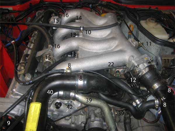
Figure 1 (numbers in the picture correspond to listed steps)
7. Remove Stock Air Filter Box, Air Flow Meter and Snorkel. note -- the car in these pictures is equipped with an aftermarket MAF, as are so many 944 turbo's with blown head gaskets. On most MAF-equipped cars, the stock filter box and airflow meter are already removed. For cars with a stock intake set-up, you need to remove the air snorkel, air filter box, and air flow meter.
8. Remove both intercooler (I/C) Pipes (figures 1 and 2). Start by removing the banjo bolt on the passenger side intercooler pipe using a 17mm box end wrench, making sure not to drop or lose the two sealing washers. I store the washers on the banjo bolt, and store the banjo bolt in the intercooler pipe, once the banjo fitting and hose is removed. On the driver's side pipe, you also need to disconnect the hose going to the bypass (BOV) valve, as well as the oil breather hose. The intercooler pipes are then removed by loosening the hose clamps holding them in place. The driver side intercooler pipe can get wedged in place and be difficult to remove. I have a trick that helps for this -- with the clamps completely loosened, the rubber coupler at the intercooler can be slid up completely onto the I/C pipe, allowing the pipe to come out easily. There is usually oil inside the pipes that help the coupler slide like this. I install the pipe the same way -- by sliding the rubber connector all the way onto the I/C pipe, positioning the pipe in place, and then slipping the coupler down onto the intercooler itself.
9. Remove Spark Plug Wires and Distributor Cap. You can leave the wires connected to the distributor cap. All that is needed is to pull the wires off the spark plugs, and get the wires free from the intake manifold. Also, remove the coil wire from the center of the distributor cap. Grip and twist the boot itself and do not be temped to pull on the wire. Remove the distributor cap with a long straight screwdriver and plenty of patience -- the two mounting screws are spring loaded and control hooks that hold the cap to its mounting cover. You need to push the screws in and twist (back and forth until you feel it unhooking).
10. Disconnect Cruise Control Cable (figure 1). This is done by removing the 10mm hold down bolt on top of the intake manifold (the bolt can be stored in that hole once the cable is free). Then, in front of the battery compartment, disconnect the cable from the control unit by sliding back the metal cage-clip and pulling the black rubber connector off the ball joint on the control unit. With the cable end free, loosen the 13mm nuts holding the cable to the bracket. It is easier to first loosen the 13mm nut on the side closest to the engine, then as soon as it breaks free, spin the other nut all the way off so that it is hanging loosely on the cable wire itself. Then you can pull the cable assembly back until you can slide the cable wire out the slot on the side of the bracket. Pull the cable out of the way over to the driver side of the engine compartment. It sometimes helps to tie wrap loose cables and wires out of the way. When reinstalling the cable, be sure to adjust the cable lock nuts so that the cable does not pull on the throttle when the cruise control is not in use -- otherwise the cable can pull on the throttle at idle. If you mark the threads before loosening the lock nuts, you can set it back to the same position on reassembly.
11. Disconnect Throttle Cable (figure 1). Unhook the throttle cable from the throttle cam. It's easiest if you open the throttle cam by hand to get slack on the throttle cable -- then just slide the anchor bullet out the slot on the side of the throttle cam. Once the cable is freed from the cam, disconnect the throttle cable from the bracket on the intake by loosening the 13mm nut nearest the windshield so that the other nut can be spun all the way off the end of the cable. With that nut hanging on the throttle cable wire, pull the cable back until the cable wire can slide out the little slot on the bracket and freed completely from the intake. Once freed, pull it out of the way on the passenger side of the motor (tie-wrapping it out of the way if needed). On reassembly, the throttle cable needs to be adjusted so that the Throttle Position Sensor (TPS) can be heard making a soft "click" when the throttle first starts to open. (The "click" is a microswitch inside the TPS that tells the DME whether the throttle is open or closed.)
12. Disconnect Throttle Position Sensor (figure 1). The throttle position sensor (TPS) is the black plastic thing on the side of the throttle body. To remove its connector, you need to pull back or remove the small wire clip that wraps around the base of the connector. I find it easiest to use a small computer electronics (or eyeglass) screwdriver to pick the wire clip out of its groove. Be careful not to launch the clip into orbit. Keep a firm grasp on the clip at all times. Once you get the connector off the TPS, you can replace the wire clip on the connector. With the clip reinstalled, the connector can be pushed straight onto the TPS when the time comes to reassemble.
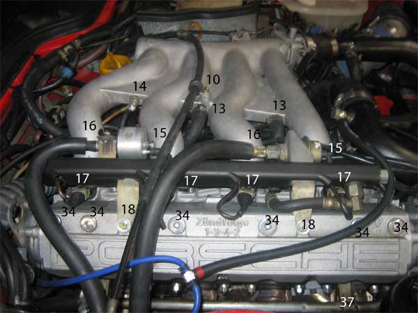
Figure 2 (numbers correspond to listed steps)
13. Disconnect Intake Hoses (figures 1and 2). Disconnect the two hoses between the 1-2 and 2-3 intake runners, by loosening the hose clamps and pulling the hoses. If these hoses are sticking, be careful not to pull too hard. The pipes the hoses fit over are known to pull out of the intake. (If that happens, you’ll need to glue them back in and hope they stay.) Consider cutting the hoses off the pipes with a razor blade and replacing them, if needed, rather than putting the pipes at risk.
14. Disconnect Vacuum Fitting (figures 1and 2). Disconnect the two hoses under the 12mm banjo bolt fittings between intake runners 3-4, with a 12mm wrench or socket. Be careful not to drop the sealing washers. I just remove the banjo fittings, and store the bolt (and its sealing washers) in the hole it came out of. Early cars have only one banjo bolt fitting -- later cars have two.
15. Disconnect FPR/Damper Vacuum Lines (figures 1 and 2). Pull the black rubber vacuum hoses off the fuel pressure regulator and pulsation damper. Inspect the hoses for cracks and replace if necessary.
16. Disconnect Fuel Lines (figures 1 and 2). Depressurize the fuel system by removing the cap nut at the front of the fuel rail using a 19mm wrench, using a shop rag to catch the fuel as it drains. Be careful not to lose the small ball bearing in the cap nut. Once depressurized, replace the cap and torque to 9 ft. lbs. Next, disconnect the fuel lines by using a straight slot screwdriver on the hose going to the fuel pressure regulator (at the rear of the fuel rail) and a 19mm open or flare-nut wrench on the hose going to the damper. There is no need to disconnect the intermediate hose running between the damper and fuel rail. (Note that the rear fuel hose in the picture above is re-routed to attached from the rear, rather than connecting in the front of the fuel pressure regulator as per the factory arrangement.)
17. Disconnect Rail Cover and Injector Connectors (figure 2). The black plastic fuel rail is removed by unlatching the three plastic hooks on the underside of the cover. The injectors have the same wire-clip arrangement as the throttle position sensor, just smaller. Use an awl or small electronics screwdriver to pull out the clip -- again being careful not to let it spring across the garage. Once the connectors are removed from the injectors, store the clips on the injectors. This avoids lost clips and makes reassembly a "snap" -- literally.
18. Remove Fuel Rail to Cam Tower Bolts (figure 2). Remove the two 10mm bolts holding fuel rail to cam tower. (Do not remove the two bolts holding the fuel rail to the intake manifold, unless you plan to remove the fuel rail and intake manifold separately.)
19. Disconnect Throttle Body Vacuum. There is a vacuum line hidden squarely under the center of the throttle body, which needs to be removed. With the intercooler pipe off, you can reach under the throttle body and pull the line off. It is a small rubber vacuum line connecting the throttle body port to a thin black plastic line, like the hoses that plug onto the fuel pressure regulator and damper.
20. Remove Allen Bolts at Rear of Intake (figure 3). There are two small Allen head bolts at the rear of the intake, which need to be removed. Us a 2.5mm Allen key to get these out. On re-assembly, it is sometimes necessary to put an awl or small screwdriver into one of these holes to line-up the bracket underneath with the holes in the intake.
21. Detach O2 Connector Bracket (figure 3). Loosen the 10mm bolt at rear of intake and slide out the bracket holing the O2 and reference sensor connectors. The 10mm bolt only needs to be loosened, not removed, so the bracket can slide out.
22. Loosen Front Perch Bolt (figure 1). Loosen the 13mm bolt at front of intake. This bolt does not need to be removed. It rests on a spade-style support bracket to hold the front of the intake secure. By loosening the bolt, it will slide up and out of the bracket perch when the intake it removed.
23. Remove Intake Bolts. There are eight intake bolts -- two at the base of each runner. They are removed using a 6mm Allen socket. If you have kept the fuel rail on the intake, you should use a ball-head hex socket on the bolt under the damper at the front of the rail. If it does not want to come out, or starts to strip, you are better off removing the remaining two 10mm bolts holding the fuel rail to the head, and pulling the fuel rail off. The injectors can be sticky, but a combination of pulling and rocking the rail will always get it off. If you remove the fuel rail from the intake, be sure to get new injector o-rings, and give them a light coat of automatic transmission fluid before reinstalling. Make sure they are fully seated, top and bottom, when reinstalling. There is no better way to start a fire than to have fuel drip out of ill-seated injectors onto the exhaust.
24. Remove Intake. At this point, the intake manifold should lift straight up and out. The dip stick tube will pull out of its port in the block along with the dip stick. When re-installing, it is worth replacing the little o-ring that seals the dip stick tube into its port in the block. It's good practice to plug the intake ports in the head with paper towels, to keep debris from getting into the ports.
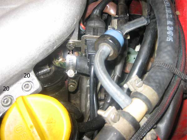
Figure 3 (numbers correspond to listed steps)
25. Remove P/S and A/C Belts. The power steering belt is loosened and removed from under the car via its turn-buckle adjuster rod. Use two 13mm open end wrenches. Both jam nuts on the adjuster rod are loosened by putting an open end wrench on from below, and pushing the wrench toward rear of the car while counter-holding the adjustment rod itself with another 13mm wrench (one of the jam nuts is reverse threaded). Once the jam nuts are loose, turn the adjustment rod itself as needed to loosen the belt enough for removal. The A/C belt is removed in the same manner, but its adjustment rod uses 15mm wrenches, and the jam nuts loosen in the opposite direction (with a wrench put on from below the car, push the wrench toward the front of the car to loosen the jam nuts). Note that both of these belts have a tension specification, using Porsche's special belt tensioning tool (9201). However, I have always found Porsche's spec to be excessively tight, so I tighten them by feel -- just like a 1950's mechanic -- and have never had a problem.
26. Remove Timing Belt Covers. Remove the 10mm bolts holding the two black plastic timing belt covers in place. Some of the bolts are easier to reach from above, others from below. With the two black plastic covers removed, remove the three 10mm bolts holding the distributor mount cover in pace over the top of the cam gear. The cover has two spring tension clips that hold it snug even after the mounting bolts are removed, so a bit of pulling (or gentle leveraging with a screwdriver) might be needed to dislodge the cover.
27. Disconnect Headers at Cross-Over. Remove the six nut/bolts holding headers to cross-over. These should be 13mm, but aftermarket nuts are often 12mm. The nuts are mechanical lock nuts (pressure nuts), which makes them hard to turn out. You need a ratchet on one side and an open end wrench on the other. A hammer can be used (with protective eyewear on as always), to hit he wrench, if necessary to break the bolts free. Soak the nuts and bolts with PB Blaster (or penetrating oil of choice) in advance if needed. A propane torch can be used to further persuade them if needed. As a last resort, it is reasonably easy to grind the bolt heads off using a Dremmel or other grinder -- just try not to damage the flanges. However you remove them, it is a good idea to replace these fasteners when reassembling. Once the head is removed, be sure to replace the two exhaust sealing rings found in the flanges on the cross over pipe. A small awl is usually most effective in getting the old rings out. Also, the header flanges and cross-over flanges rarely line-up once you unbolt them. To get the bolts back in, first loosen the headers at the head so they can move about some. Then use a screwdriver as a lever, by inserting it into one set of bolt holes and prying in the direction needed to line up the other bolt holes.
28. Set Engine to TDC. Set engine to TDC (on the No. 1 cylinder on the compression stroke) using a 24mm deep dish socket on the bolt in the center of the main crank pulley. Turn the motor clockwise (as you face the motor) until the white line on the cam gear matches up with the alignment mark in the cam gear housing. Then confirm that the engine is at TDC by checking that the alignment mark on the flywheel aligns with the mark on the bell housing. It's not easy to find the flywheel marks -- you need to lean over the engine from the driver side and get your head straight over the top of the bell housing. If you shine a flashlight straight down and peek around enough clutter, you will find the marks.
29. Remove Timing Belt from Cam Gear. When you remove the head, there is no need to remove or tamper with the balance shaft belt. You only need to pull the timing belt off the cam gear. Loosen timing belt idler using 17mm socket (or loosen the automatic tensioner on later cars), so that the timing belt can be slipped off the cam belt. If you are not changing belts, there is no need to remove the belt from the crank gear -- simply move the top loop of the timing belt out of the way once it is off the cam gear. On reassembly, it is critical that the belt be aligned and tensioned properly. The procedure for tensioning the timing belt is well-documented on the web -- be sure to read up. In a nutshell, slip the belt back on the cam gear, confirming the flywheel and cam gear are both set to TDC, and pre-tension the belt by feel. On the '86, the belt is tightened by turning the tensioning roller counter-clockwise. Then crank the motor clockwise (using a 24mm socket on the main crank pulley bolt) two revolutions until the cam gear mark is back to TDC. Then back the motor up about 10 degrees (1.5 teeth on the cam gear) and place the 9201 tool on the long upper run above the water pump. The spec for a used belt is 2.7 +/- .3 (more than 2000 miles on belt); or 4.0 +/- .3 for a new belt (less than 2000 miles on belt). Once tensioned, torque tensioner roller nut to 33 ft. lbs. It can take several tries to get it right. Be sure to check the tension after 2000 miles if you use a new belt.
30. Disconnect Test Port from Cam Tower. Remove the 10mm bolt holding the electronic test port to rear cam tower hoist bracket. Note that the "nut" on the rear side is welded in place and cannot be removed.
31. Disconnect Co2 Test Port. Disconnect Co2 test port bracket from rear of cam tower by removing 10mm bolt and nut.
32. Move Power Steering Reservoir. Loosen the big hose clamp and slide the reservoir out of its bracket and swing it out of the way.
33. Remove Oil Filter. A strong grip is all that's needed usually. Be sure to wet the rubber seal with oil on the new filter.
34. Remove Cam Tower Access Plugs (figure 2). Remove the six 8mm Allen-key plugs on top of the cam tower, using an 8mm Allen socket. These can be tight, so use the biggest breaker available.
35. Remove Front Cam Tower Bolts. Remove two 10mm bolts holding the rear timing belt cover to the end of the cam tower (below the distributor, just under the path of the timing belt beow the cam gear). On reassembly, be sure to replace these before reinstalling the cam belt. With the timing belt in place, it is very difficult to install these bolts without stripping their holes.
36. Remove Cam Tower Bolts. When you loosen the cam tower bolts, oil will drip on the headers. The oil will smoke off, but it is a fire risk and a nuisance. To avoid this, cover the headers with plastic wrap before loosening the cam tower bolts. Then remove the fifteen 6mm Allen-head bolts holding cam tower in place – six of which are inside the cam tower under the plug holes. Unfortunately, most 6mm Allen sockets will not fit inside the cam plug holes. The best tool is a long neck 6mm Allen socket like those sold by Snap-On. You can also make the necessary tool from a regular 6mm Allen key (the black L-shaped keys sold everywhere) by cutting off the L portion so that you have a long 6mm hex shaft. You can then use this shaft with a 6mm socket as a make-shift long-neck hex socket. There is no specified order for removing/installing the cam tower bolts. Instead, loosen them evenly a little bit at a time, so that nothing binds as the tower raises up against the valve spring pressure. Removing the inner cam tower bolts is a bit like the old game "Operation" -- the Allen key usually gets a good bite on the bolts to loosen them, so when they are ready to come out, you just slowly withdraw the Allen key and pull the bolt head through the cam tower plug holes. If you drop a bolt, you can get it out once the cam tower is off, or with a magnet on a stick.
37. Remove Heater Coolant Pipe (figure 2). Remove coolant pipe running over the top of the headers. If you have removed all the cam tower bolts, this pipe can be removed by simply loosing the hose clamps on either end and removing the hoses.
38. Remove Cam Tower. First make sure all loose wires and hoses are out of the way. There are eight round lifters in the cam tower that can slide out and fall when removing the tower. You need to avoid dropping and mixing them up, since they wear with their corresponding cam lobes. To avoid dropping them, you want to rotate the cam tower off the head, rather than lifting it straight up -- as if it were on a piano hinge along the top of the headers. It can help to lower the passenger side of the car, to further tilted the tower before removing. Also keep track of the two dowel pins at the front and rear of the tower -- they can stick in the head or tower (or one in each) and can also fall out and get lost. Torque the cam tower bolts to 15 ft. lbs. when reassembling, working in stages to seat the tower evenly. Be sure to clean the mating surfaces thoroughly. Always use a new gasket under the cam tower, making sure the "oben/top" side is up (you can block oil galleys to the tower otherwise). When reassembling, pull each lifter out and put assembly lube on the flat cam-facing surface, and on the sides, and on the valve-facing button. This keeps them from falling out when reassembling and protects them when first restarting the motor. Also be sure the engine and cam are still set to TDC and remain at TDC while bolting down the tower. Before installing the head, I often rotate the engine 20 degrees (or so) forward, so that all pistons are below the deck. This way, if the cam moves while installing the cam tower, the valves cannot run into any pistons. Once the cam tower is on (with the cam gear still set to TDC), I carefully back the engine up to TDC before installing the cam belt.
39. Remove Front Coolant Pipe (figure 1). Remove the water pipe at the front of the motor by removing 10mm bolt holding its bracket, and hoses on both ends. It's easiest to unbolt the coolant neck from the head (step 40), and then remove the pipe with the coolant neck still attached.
40. Remove Water Neck (figure 1). Remove two 6mm Allen-key bolts around the water passage at the front of the head. Also remove the mounting piece under coolant neck, attached with two additional 6mm Allen-head bolts.
41. Remove CV Mount/Coolant Pipe (figure 4). With all these parts removed, it looks like you should be able to remove the head. Don't be fooled. There is a coolant neck on the rear driver side of the head, hiding under the cycling valve (CV). The CV mounting bracket and the coolant neck combine to trap a collection of hoses and harnesses. The picture below show the basic idea, with all the clutter removed to highlight the challenge. You need to remove the cycling valve, its mounting bracket and the cooling neck, so that the head does not get hung up when you try to pull it off. Start by removing the three hoses on the cycling valve -- the ports snap off easily, so use care (and/or a razor blade) when removing the hoses. Next, remove the two small bolts holding the cycling valve to its bracket (yellow dots in picture below) using a 4mm Allen wrench. Remove vacuum lines going to the thermal switch and remove thermal switch from the coolant neck with a 19mm wrench (green dot below). Loosen the hose clamp on the coolant neck and remove the hose connecting the neck to the heater valve (blue dot below). Finally, remove the two 13mm bolts (red dots below) holding the CV bracket and coolant neck to the head, and remove CV bracket and coolant neck.
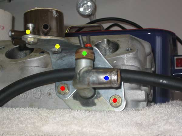
Figure 4
42. Remove Small Water Passage Head Bolts (figure 5). Remove the two small head bolts at the front driver side of the head, using a 6mm Allen key. These bolts help seal the water jacket port at the front of the head. Torque to 15 ft. lbs. on reassembly. The front bolt also holds a small bracket for the clip on the oil sender wire that runs across the front of the motor.
43. Remove Head Nuts. Remove head nuts in the sequence shown in figure 5. Make at least three passes over the head, in sequence, loosening the nuts a bit more each time. On reassembly, it is important to tighten the nuts in the numbered sequence, in three passes using the following torque specs:
First pass: 15 ft. lbs.
Second pass: 90 degrees (1/4 turn)
Third pass: 90 degrees (1/4 turn)
The nuts can be marked with a White-Out pen or a special torque angle gauge can be used to measure the 90 degree turns. Torque angle gauges are available at good auto parts stores and are relatively inexpensive. The threads of the stud and the bottom of the nuts should be lightly oiled before installation. Needless to say, the washers are an essential part of the system -- don't proceed without them! Also, see comments below regarding head studs and nuts.
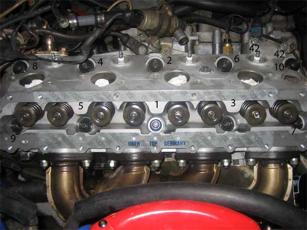
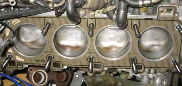
Figure 5 (head nut sequence and location of head bolts referenced in step 42)
44. Remove Head with Headers. Double check that all hoses and wires are tucked out of the way -- use tie wraps temporarily if needed. Once all is clear pull head straight up and off the block with the headers still attached. If the head does not seem to be loose, tap it with a rubber mallet to unseat it. If it still does not budge, double check to make sure all 10 head nuts/washers are removed, along with the two small bolts listed in step 42, and that the header to cross-over bolts are all removed. When reassembling, the head can be reinstalled with the headers still attached. If you install the head without the headers installed, you will need to remove the exhaust studs (preferably on the bench before installing) then position the headers in place in the car and reinstall the studs. Alternatively, you can disconnect the motor mount on that side of the motor and jack the motor a bit to create the clearance needed to install the headers over the exhaust studs. Anytime the headers are removed, be sure to use new exhaust gaskets, oriented so the shiny side faces the headers.
INSPECTION AND REASSEMBLY PREPARATION
A. Clean All Sealing Surfaces. Be sure to clean all gasket-facing surfaces, including the cam tower gasket area, water ports, intake and exhaust ports, and the head and deck sealing surfaces. I like to use a Scotchbrite pad on the tops of the cylinders and the deck sealing areas (available in the cleaner aisle at your local grocery store).
B. Valve Job. It's common to send the head out for reconditioning before reinstalling. If you opt not to do so, be sure to check the head for flatness with a precision straight edge and feeler gauge. The straight edge should be used end-to-end and corner-to-corner on the head. The head should be within .05mm of flat in all directions. If it is not within this spec, be sure to have the head machined flat, since the lack of flatness may be contributing to the leak.
C. Head Studs/Nuts/Raceware. Contrary to popular opinion, I have found nothing published by Porsche suggesting that the factory head studs cannot be re-used. However, Alldata does say to use new nuts. The studs are glued in place with red loctite and can be extremely difficult to remove. If you opt to remove the head studs, I highly recommend you get the Snap-On collet-style stud remover and a large T-bar breaker bar. The Snap-On remover grips the studs tighter than anything else available, and a T-bar helps you avoid side-loading the stud. If the engine is out of the car, it also helps to heat the block with MAP gas down where the studs screw in. Raceware suggests that its studs be installed with a small amount of plumber's Teflon and without loctite. New studs should be set so they measure approximately 73mm high above the deck. Raceware studs should be torqued in the factory sequences in three passes - 25, 45 and finally 65 ft. lbs. (For added clamp, at least a few well-known engine builders cheat a bit on the final torque and tighten the nuts up to 75 -85 ft. lbs. when using Raceware or ARP studs.)
REASSEMBLY CHECKLIST -- HEAD GASKET REPLACEMENT
CLICK HERE FOR PRINTER-FRIENDLY CHECKLIST
¨ Install New Head Gasket. Right side up! No sealant.
¨ Install 2 Exhaust Sealing Rings. In cross-over flanges. (see step 27)
¨ Install Head/Headers. Position head with the headers attached.
¨ Install Header to Cross-over bolts. Align and insert bolts. Don't torque yet.
¨ Torque Head Nuts. (See step 43, figure 5)
¨ Torque Exhaust to Cross-over Bolts. 15 ft. lbs. (see step 27)
¨ Install Front Water Passage Head Bolts. 15 ft. lbs. (see step 42, figure 5)
¨ Replace Rear Coolant Neck and CV Bracket. 14 ft. lbs. (Step 41, figure 4)
¨ Replace Thermal Switch and its Vacuum Lines. (Step 41, figure 4)
¨ Replace Cycling Valve and its Hoses. (Step 41, figure 4)
¨ Replace Mount for Front Coolant Neck. 15 ft. lbs. (step 40, figure 1)
¨ Replace Front Coolant Neck on Mount. 15 ft. lbs. (step 40, figure 1)
¨ Replace Front Coolant Pipe and Hoses. 7 ft lbs. (Step 39, figure 1)
¨ Install Cam Tower Gasket. Right side up! No sealant. (see figure 5)
¨ Apply Assembly Lube to Lifers. (see step 38)
¨ Confirm Motor is still at TDC No.1.
¨ Install Cam Tower with Cam Gear Mark Set to TDC. 15 ft. lbs. (see step 38)
¨ Install Front Timing Cover/Cam Tower Bolts. 6 ft. lbs. (see step 35)
¨ Replace Six Cam Tower Access Plugs. 29 ft. lbs. (see step 34, figure 2)
¨ Install New Oil Filter. (see step 33)
¨ Put Back Power Steering Reservoir. (see step 32)
¨ Re-attach Co2 Test Port. (see step 31)
¨ Re-attach Electronic Test Port to Cam Tower Hoist Bracket. (see step 30)
¨ Set Timing Belt Tension. (see step 29)
¨ Install Distributor Mounting Cover. 6 ft. lbs. (see step 26)
¨ Install Timing Belt Covers. 6 ft. lbs. (see step 26)
¨ Install Heater Pipe and Hoses. (see step 37)
¨ Reinstall Accessory Belts. (see step 25)
¨ Position Intake Gaskets. (line up injector notches; No.1 goes on upside down)
¨ Position Intake with Dip Stick and Fuel Rail Attached.
¨ Install 8 Intake Bolts. 15 ft. lbs. (ensure gaskets are in place)
¨ Tighten Perch Bolt at Front of Intake. (see step 22, figure 1)
¨ Re-attach O2 Connection Bracket. (see step 21)
¨ Install Allen-bolts at Rear of Intake. (see step 20, figure 3)
¨ Re-attach Vacuum line under Throttle Body. (see step 19)
¨ Install Fuel Rail to Cam Tower Bolts. 6 ft. lbs. (see step 18, figure 2)
¨ Re-connect Injector Wires/Replace Plastic Cover. (see step 17, figure 2)
¨ Re-attach Fuel Lines. (see step 16, figure 2)
¨ Re-attach Vacuum Lines to FPR and Damper. (see step 15, figure 2)
¨ Re-install Vacuum Fitting Lines on Intake. 7 ft. lbs. (see step 14, figure 2)
¨ Re-install Vacuum Hoses Between Runners. (see step 13, figure 1 and 3)
¨ Re-connect Throttle Position Sensor Connector. (see step 12, figure 1)
¨ Re-install/Adjust Throttle Cable. Adjust for TPS click (see step 11, figure 1)
¨ Re-install/Adjust Cruise Control Cable. (see step 10, figure 1)
¨ Re-install Distributor Cap and Wires.
¨ Re-install I/C pipes and Coupler Hoses. (see step 8, figure 1)
¨ Re-install Boost Bolt in I/C Pipe. (see step 8, figure 1)
¨ Re-connect Hose from I/C to BOV and Oil Breather. (see step 8, figure 1)
¨ Re-install Air Filter Box and Air Flow Meter. (see step 7)
¨ Refill Oil.
¨ Refill Coolant/Vent.
¨ Re-connect Battery.
¨ Replace Belly Pans.
¨ Lower Car.
¨ Start Car -- Check for Fuel or Coolant Leaks.
PARTS LIST
Radiator Drain Plug: 944 106 353 01
Seal for Radiator Drain Plug: 944 106 354 00
Seal for Oil Drain Plug: 900 123 049 30
Dipstick tube O-ring: 900 174 044 40
Head Gasket Set
Head gasket: Use Widefire Gasket
Intake Gaskets (4): 944 110 163 05
Exhaust rings (2): 944 111 205 04
Exhaust Gaskets (4): 944 111 196 01
Coolant Neck Gaskets (3):
944 104 311 06
951 104 311 03
928 106 197 04
Cam Tower Gasket: 928 105 199 12
Header to Crossover bolts/nuts (6):
Washers: 999 025 078 02
Bolts: 900 074 283 02
Locking Nuts: 999 084 052 02
"WHILE YOU'RE IN THERE" PROJECTS
Update '86 venturi with '87 hoses
Replace vacuum hoses
Replace Head Studs
Replace Timing Belts
Replace Coolant Hoses
Replace Accessory Belts
Replace Plugs/Cap/Rotor/Wires
Valve Job/Head Machine Work
Replace Injector O-rings
Have injectors cleaned
Throttle Body Reseal