OK, I'm going to cut right to the chase here. Constantine's replacement torque tube bearing assemblies are the ultimate solution if you want to rebuild a torque tube to be as bulletproof as possible. No other solution comes close to solving as many problems as this one does. Note that I have no business interest in this product. I have a very strong mechanical intuition and I could see right away what many of the long-term benefits of this design are. I'm just a satisfied customer. I am thinking VERY long-term here. I was interested in a solution that could be rebuilt more than once.
I had known for 4+ years that my torque tube bearings were going. Back in '05 I noticed a quiet whirring sound underneath and with a mechanic's stethoscope I determined that my torque tube bearings as well as my transmission input shaft bearing were going to need replacing in the not-too-distant future. I eagerly read any threads on various forums that discussed torque tubes. It was obvious that original replacement TT internals could not be obtained without buying a new TT from Porsche. IIRC someone stated at one time that that's something like $1800.
Rebuilds were available from suppliers like 928 International and Devek who had enough old torque tubes laying around that they could find enough usable parts to create one rebuilt unit. Jim Bailey stated at one point that sometimes a torque tube from one of their parts cars contains no useful parts at all other than the tube and the shaft, sometimes just the tube, other times all parts except bearings are in good enough shape to be re-used(Translation: I had no way to be sure the carriers in my TT were re-usable.). Due to the unavailability of an original-spec bearing, all rebuilds(including all vendors and all DIY rebuilds) were performed with bearings that could not withstand as much heat as the original bearings. There were many other issues with rebuilding torque tubes, especially for the DIYer who wanted to rebuild his own torque tube. Below is a list culled from threads on the subject, recollections of my past research, and some more current and specific information that I have picked up from discussing Constantine's design(and the general issues) with him.
Problems with parts used for rebuilding torque tubes:
- Carriers
- The rubber vulcanized around the outside of the original carrier would compress and harden with heat and time, eventually losing its grip on the inner wall of the tube and migrating from its original position in the tube("bearing walk"). It's pretty common knowledge that German rubber products from this era are crap, this is yet another example.
- The sheetmetal stamping at the core of the original carrier could only stand having bearings pressed in and out a very few times before it would deform to the point where it would no longer grip the bearing adequately. Constantine tells me that he experimented with this and found that the bearing was no longer a tight press fit(on a cold part) after removing/installing bearings 3 or 4 times. Once the part heats up this could present a real problem, even after one or two rebuilds.
- Replacement carriers that I've seen made of solid aluminum would transmit more unattenuated vibration to the bearings, as well as heat. Additionally they would transmit more bearing nois to the outside, which is not desirable for a street car.
- Drilling through the torque tube to retain worn original, all-aluminum, or all-delrin carriers will result in burrs on the inside of the tube, and will be nearly impossible to line up again at the time of a subsequent rebuild, very likely resulting in more holes being drilled. Subsequent removal of the carriers will result in the burrs tearing up the vulcanized rubber on the outside of the carriers.
- Clearly Porsche took extensive measures to attenuate vibrations reaching the bearings. Solid aluminum or delrin parts would defeat these efforts.
- Replacement Bearings
- The original 6006 bearing used in 928 torque tubes was specified as a C5 clearance. This is more clearance(on the order of microns) than currently available bearings; the additional clearance was intended to allow the bearings to realize the intended service life under the expected heat conditions in the application.
- More specifically, the bearing itself generates heat under operation as well as getting some heat soak from it's environment. This heat will affect the internal clearances of the bearing making them tighter, and in tight tolerance bearings(e.g. C3 clearance), will cause the ball bearings and their races to wear on each other. This will cause deformity of both and cause the bearing to fail. That's why Porsche specified the looser C5 rating for it's rather small 6006 sized bearing.
- The closest match available today in a 6006 size is a C3 clearance bearing, quite a bit tighter(therefore less heat-tolerant) than original.
- IMHO the OE bearings are the minimum size that will work. A more robust bearing would be highly desirable.
- Inner Bushings
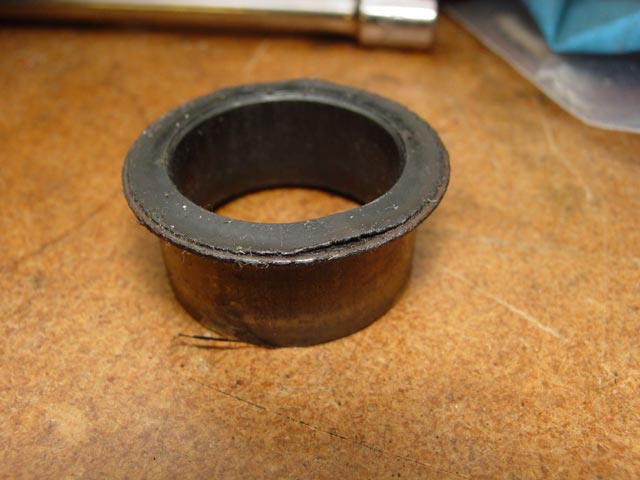
- The original inner bushings are a formed steel piece with a hard rubber or plastic liner that is swaged to the inner race of the bearing. These pieces are not always re-usable(see pic below).
- Delrin/nylon/etc. replacement bushings available from various sources share the common trait that they are not retained in the bearing in any way. If you push the driveshaft in too far then have to pull it back out, the bushing may move out of the bearing. If this happens to the center bearing you may never know. Also, with nothing to retain them, they may move out of the bearing somewhere down the road, resulting in another, premature TT R&R.
- Aluminum inner bushings will transfer all vibration directly to the bearing races without attenuation. This is probably not an issue in race applications where you may tear down the TT every season or two, but IMHO is less than ideal for a street car where longevity is important. Delrin is not much better. Although old, hardened inner bushings may seem to be the consistency of Delrin they were much more compliant when new.
- A too-rigid replacement inner bushing design will, as the central shaft flexes, cause angular misalignment of the bearings, or at least misalignment forces will be transmitted to the bearing. Any solution has to have a bit of "give" to it, as the original design does.
- (It bears repeating)Clearly Porsche took extensive measures to attenuate vibrations reaching the bearings. Solid aluminum or delrin parts would defeat these efforts.
- The original inner bushings do not grip the driveshaft very well; nor do aluminum or Delrin replacements. This is evidenced by the shiny rings left on the driveshafts.
- Rebuild Process
- Drilling/screwing, as already mentioned, will be very difficult to re-use without having to drill new holes on each subsequent rebuild.
- Moving the center carrier out of position is always a risk, especially if a very tight-fitting inner bushing is used. This is especially problematic with the center carrier, which cannot be checked after assembly.
- Inner bushings may be pushed out if the driveshaft is installed too far then backed out.
- Any misalignment of the carriers upon assembly will exacerbate the above issues.
- Other issues
- Damper weight is currently not rebuildable, and when its rubber mounts fail it acts like a slide hammer, moving the bearing carriers around. Note this piece was omitted on GT models.
- The torque tube is not an easy part to R&R, especially without a lift and helping hands. Most people would like to have a high level of confidence that once rebuilt, the TT will not have to be serviced again any time soon.
- Replacement Carriers
- Offered in aluminum and steel versions -- steel to serve as a damper(to compensate for the removal of the factory damper weight) and aluminum for applications where weight savings is more of a concern, e.g. racing.
- Carriers have a rubber shell vulcanized to the outside, bonded to an irregular profile on the outer surface of the metal carrier to aid long-term retention.
- Carriers have roughly 2.5x the surface area in contact with the inside of the torque tube compared to the original carriers. This is intended to eliminate "bearing walk" as well as any angular misalignment.
- The rubber compound used has been proven to work for extended periods in hot, oily environments without breaking down. This bodes well for long-term use where the user is thinking in terms of keeping their car for hundreds of thousands of miles
- The carriers are designed to be easy to rebuild, with a standard retaining ring used to retain the bearing.
- Replacement Bearings
- Larger, stronger 6008 series C4 clearance bearings. This has been determined to have equivalent heat tolerance to the smaller 6006 C5 bearing that Porsche used. What this means is, the bearing will not lose its clearance between the balls and the races as it heats up, and so will not be subject to the accelerated wear that a tighter clearance(C3) bearing would suffer from.
- Increased size allows for better heat-soak properties.
- 40mm bearing ID allows more room for a robust inner bushing design.
- Inner Bushings
- Inner bushing is metal with a precise fit to the ID of the bearing, retained by a circlip.
- Vulcanized rubber lining on inner bushing helps attenuate vibration that is transmitted to the bearing, absorbs any angular misalignment as the shaft flexes, and simplifies assembly.
- Simplified Rebuild Process
- Disassembly of the old torque tube took me approx. 20 minutes.
- Cleaning and prepping the torque tube for the new carriers took approx. 30 minutes.
- Final assembly of the torque tube took a bit less than an hour.
- No threaded rod was used in the process, no special fabrication of tooling is necessary(though I went a bit beyond).
- The project could have been completed in much less time if I hadn't been taking so many pictures along the way.
It took about two more weeks for the bearings to arrive after I completed my clutch assembly. This was about six weeks after Constantine and I had started talking about having me act as an early adopter/reviewer/long term tester. Constantine repeatedly warned me that he could not promise an exact delivery date, since he was still working with the outfit that was performing the vulcanization on the outer carrier to incorporate some last-minute tweaks on the profile of the rubber. This was going to take some time, as mold-making is a precise, tedious and time-consuming art. Additionally there were process issues to be worked out. Vulcanizing rubber to a heavy aluminum vs a heavy steel part entailed certain tweaks due to the different heat transfer characteristics of the two materials.
I was perfectly happy to wait for the parts, since I did not want to have to get back into the TT any time soon, and having seen a not-very-detailed pic of the part, and having discussed the design with Constantine, I felt it would be worth the wait. The exercise of riding my bicycle ~4 miles each way to work was good for me anyway.

On to the pics and the writeup.

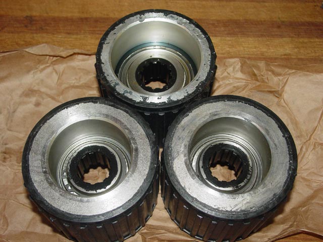
First off, here are the parts I received from Constantine, minutes after unpacking them. IIRC the one at top center is the aluminum one. It was instantly obvious that these are high-quality parts.
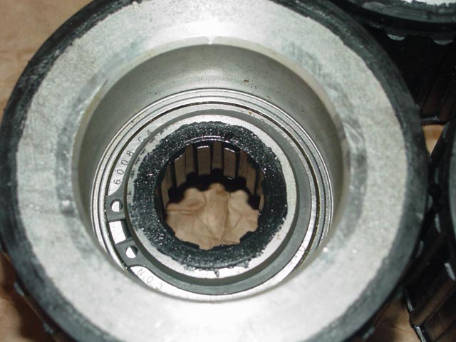
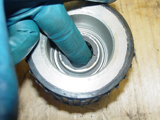
Here is a close-up of the captive side of the bearing(the side that butts against the step inside the carrier), showing the circlip that retains the inner bushing. There is a thin anti-corrosion coating sprayed on the exposed metal.
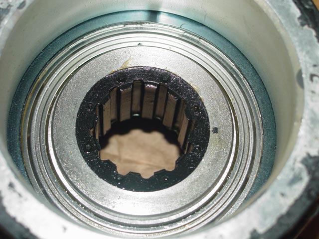
This close-up of the opposite side of the bearing shows the hat-shaped inner bushing with its vulcanized center, and the retaining ring that holds the bearing in place within the carrier. If and when these carriers need to be rebuilt they should be very easy to refurbish.
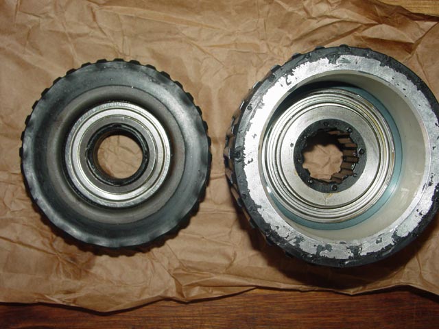
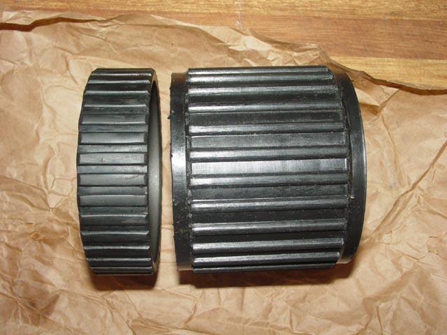
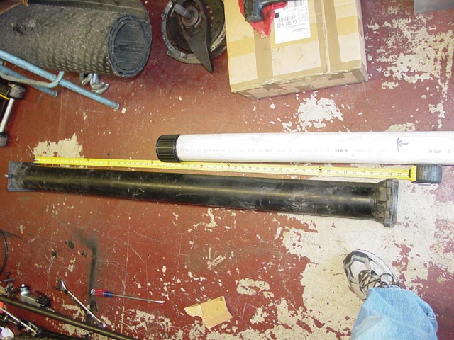
Here are the original and replacement carriers side-by-side, bearing insertion(into the carrier) side up. The carrier on the right looks larger because it is taller and closer to the camera. Still, the difference in size between the OE 6006 bearing and the replacement 6008 bearing is remarkable.
Here are the original and replacement carriers side-by-side, bearing insertion(into the carrier) side down. Nothing especially interesting to note here that hasn't already been said, I just included this angle for completeness.
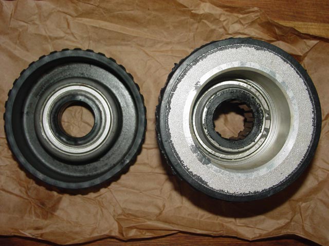
The side view really illustrates one of the major advantages of Constantine's product. With ~2.5x the surface area gripping the inside of the torque tube compared to the OE unit, it seems unlikely that these will be able to move around like the OE units do.
I started disassembly of the Torque tube when Constantine told me the parts had been shipped. He had a recommended procedure that he kept close to the vest until that time... I think he feared my sense of humor.
With few exceptions(the order of the 3" PVC usage, the mineral spirits, the hand sledge) I followed the procedure that Constantine recommended.The tools needed to R&R the bearings were:
- 3' section of 3" PVC
- 2' section of 3" PVC
- Hardwood broomstick(expendable)
- ~1' section of 2x2
- Scotchbrite pad(Metal stripping)
- Deadblow hammer/rubber mallet
- Chemicals:
- Brake cleaner(Mineral spirits too if handy)
- WD-40
- KY Jelly
- Optional:
- 2 lb hand sledge(greatly speeds driveshaft removal)
- 4' section of 1" PVC
- 1" Female to 2" Male PVC bushing
- 2" PVC coupler
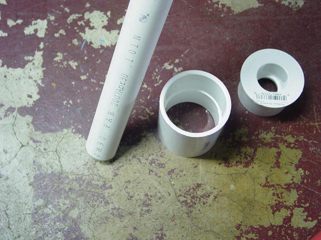
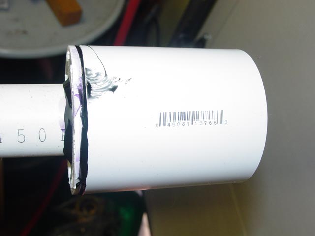
Before I started on the rest of the project I glued the three pieces mentioned above together so they would have an opportunity to dry before I needed them. The black ABS glue is not the right glue for PVC, but I figured it would be good enough -- and it was.
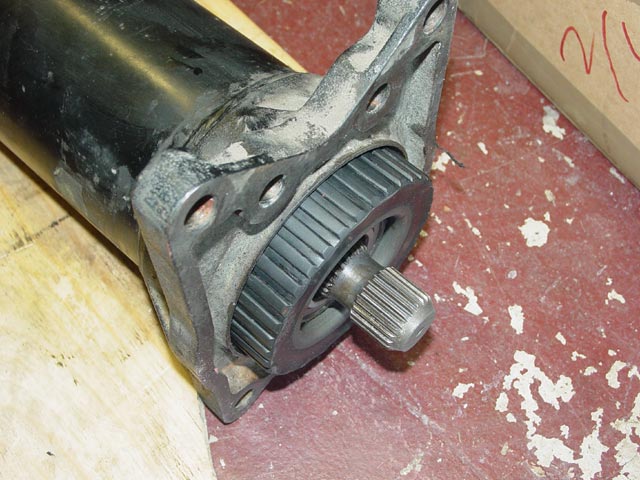
The drive shaft was extremely clean -- it looked new to me. No corrosion, no evidence that the lube recommended in the WSM had been applied(which would imply service by a factory tech).
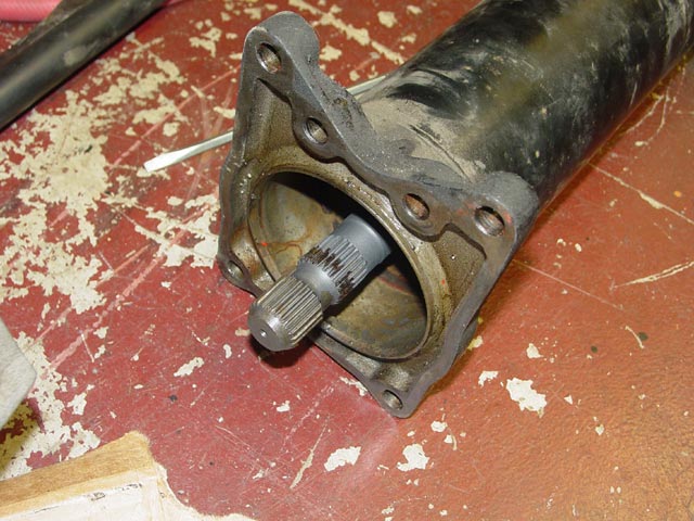
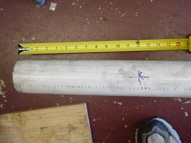
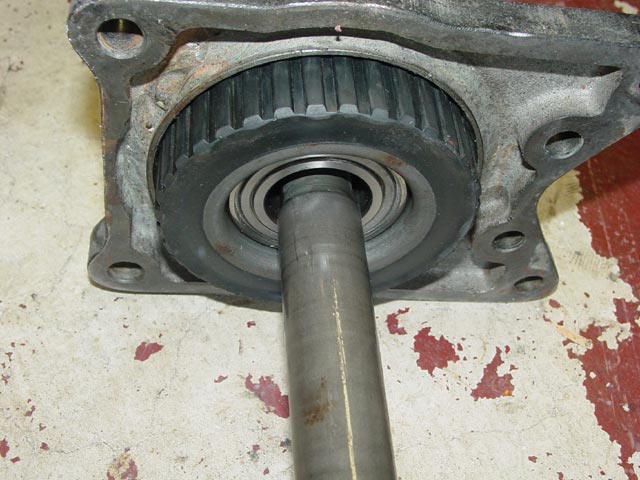
The rear bearing looked like it may have walked forward upon initial inspection, but it turned out to be ~11.5" from the rear flange which as I understand it is about right. Tom at 928I and Constantine both told me that the bearings should be about a foot from the end. This makes perfect sense, since the shaft is supported at each end by the input shaft bearing on the transaxle and the pilot bearing up front. With the center bearing in the center of the 5 foot long torque tube, the unsupported lengths of drive shaft work out to be(rear to front): 12", 18", 18", 18"(approx, incl. stub shaft).
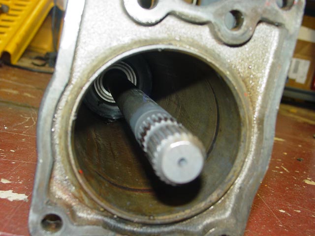
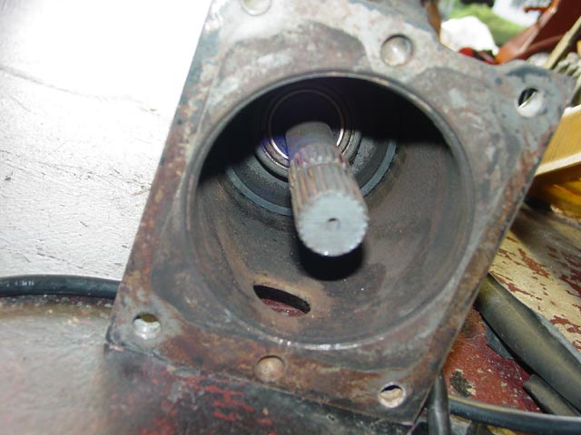
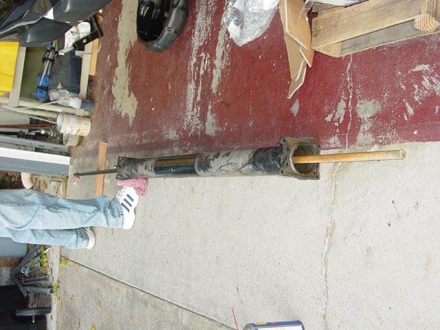
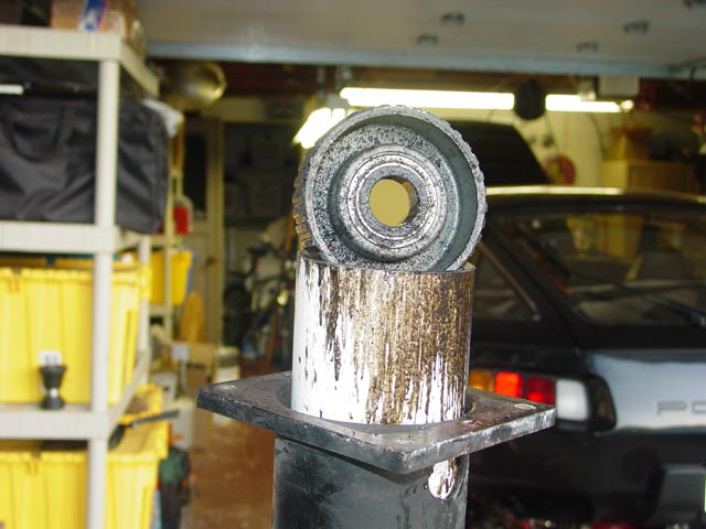
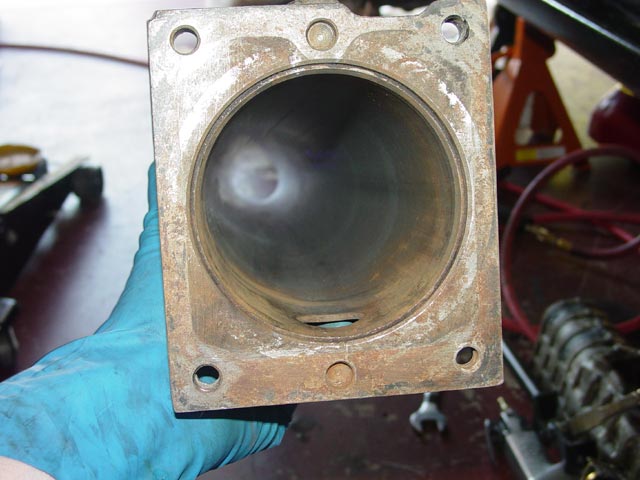
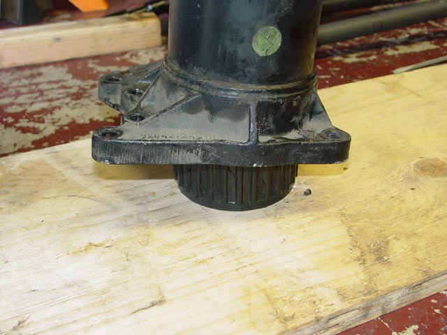
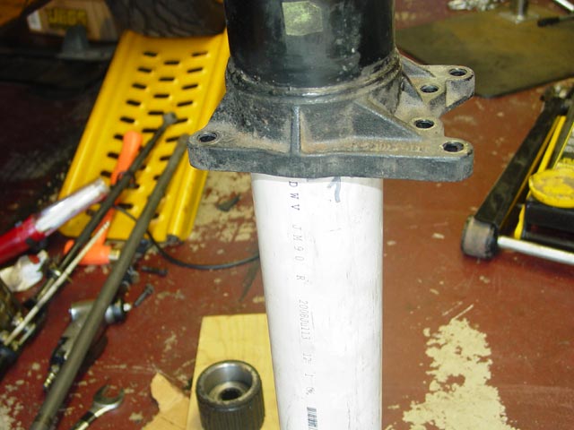
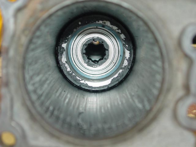
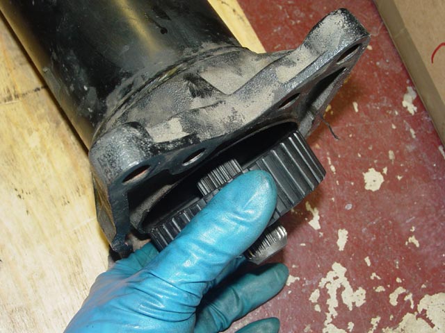
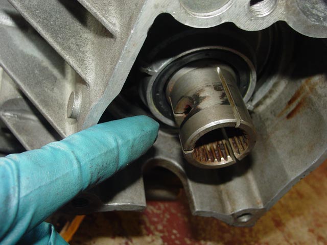
The front of the torque tube had quite a bit of rust in it, no doubt due to the fact that the inspection plug was missing. As I mentioned on the Analysis Page, this bearing had walked forward quite a bit. It had walked almost an inch forward of where I found it, then moved backward -- apparently on its own, but there is no way to be sure. I saw no tool marks or other evidence that it had been pushed backward manually. It's a bit hard to see in this pic, but the bearing was right at the edge of the large diameter, apparently it had walked forward to the point that it was no longer supporting the shaft at some point in the past.
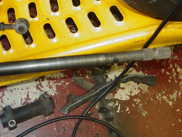
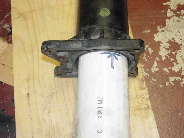
Looking at the driveshaft you can see that the carrier was originally about a foot from the end of the tube, then it walked forward in stages over time. The bright ring near the end of the large diameter is where the carrier was when I took it apart. I find it interesting that some have said that the carrier should be 6" from the end of the tube. This would place it about where I found mine, which is a precarious position IMHO. It seems that the original position was about a foot from the end of the shaft.
Removal of the shaft was fairly straightforward. Constantine recommended a rubber mallet for this task, but that seemed like a lot of work to me -- rubber mallets don't weigh much.
 Having determined that the orientation of the inner bushings called for moving the shaft from rear to front if I wanted to minimize the risk of grenading them, I started driving the shaft forward with a 1' wood 2x2 and a 2lb hand sledge. DO NOT hit the shaft directly with any sort of metal hammer. Use whatever length you need to get the shaft flush with the first bearing; if that bearing has moved you may need a longer piece. You could use the broomstick for this but IMHO that would be more of a hassle for this initial step. I did not plan to re-use any of the original parts, but wanted to preserve them in case one of the local 928 crowd might have a need for them. Also I wanted to get a good evaluation of their condition.
 Once I had moved the shaft flush with the rear bearing, I switched to a hardwood broomstick. Using a heavy hammer like this took some care to avoid shattering the 2x2 or broomstick. The idea is to be patient and only hit hard enough to move the shaft a little at a time -- try to hit a home run and you'll end up with toothpicks. Once the shaft was out a ways I supported it with a length of 2x2 so it wouldn't bind. I had a friend hold the torque tube to keep it from moving(with a rag to protect his oh-so-white shoes
)
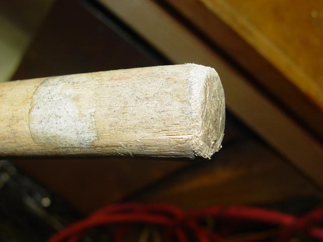
I was kind of pushing the limits of what the 2x2 could handle.
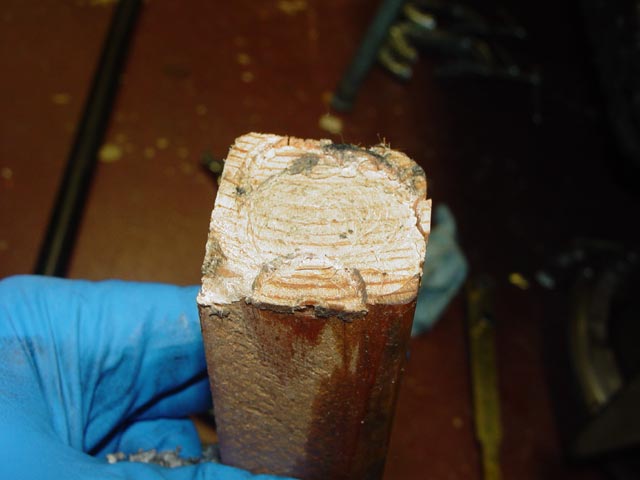
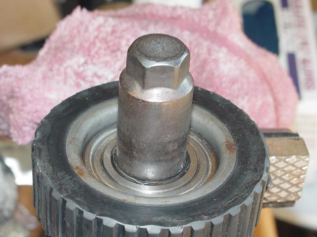
Same for the broomstick. This is the end that I was hammering on.
I basically knew it was going to cost me a broomstick -- here's the proof.

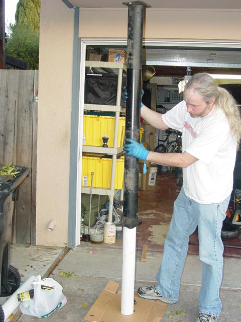
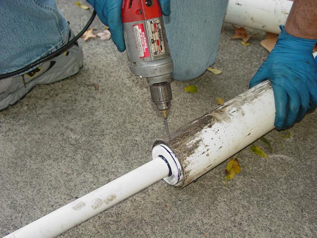
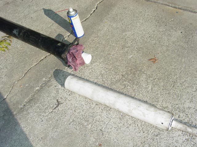
The next step was to spray a generous coating of WD-40 into the TT while rotating it, spraying through the end bearings to thoroughly coat the inside of the TT and making sure that the forward end where the bearings would exit had a good coat. I laid out a small piece of plywood with a piece of cardboard on top of it, then stood up the 3' section of PVC in the middle. I then slipped the TT down over the PVC pipe.
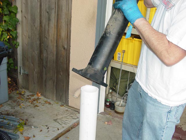
I then pounded the torque tube on the pipe, driving the bearings upward. I could feel the resistance increase as the rear and middle bearings made contact and had to move together, but even so it only took a couple of minutes tops to get down almost to the end of the PVC. Be careful at this point, you don't want to slam it down on the flange, even with the plywood in place. It would take a lot to bend the flange but sometimes the bearings will move easily for a few inches before they catch again. Best to be careful as you near the end.
Next, I lifted the TT off of the 3' pipe, and inserted the 2' pipe...
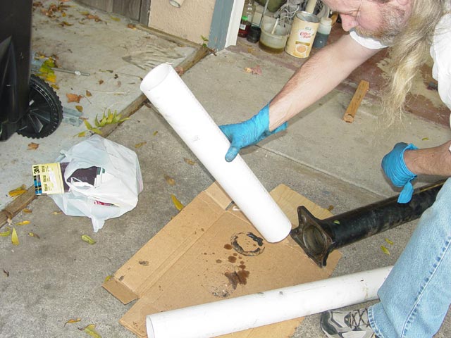
...then reinserted the 3' pipe...
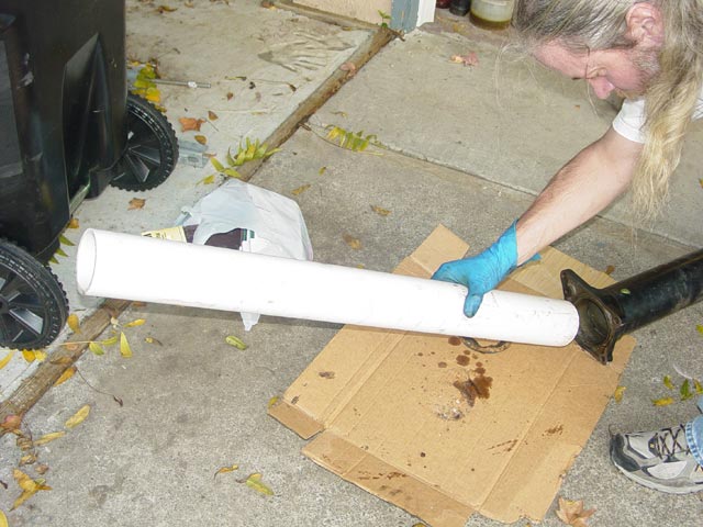
...then tilted it up and continued pounding. This was the reason for the staggered lengths -- at the second step there is 1' of PVC still engaged in the TT so there is no issue trying to line things up. A full 5' length would be too long to get the process started unless I was standing on a ladder. With equal length sections it would be a PITA getting the second one started.

Once the carriers get to the end it's time to slow down, since it will get easier as each bearing comes free.
Done at last. The whole disassembly process took maybe 20 minutes, getting the carriers out took all of 3 minutes. The bearings were obviously shot. The grease was gone, and the bearing races made a ringing, rattling sound. Good riddance!
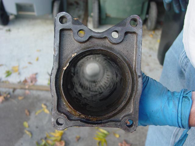
The next step was to clean out the torque tube itself. As far as I could tell this TT had never been apart. The inner bushings still had pristine factory-looking swage marks and the bearings were FAG bearings. The grease that you see below was apparently used by Porsche or their subcontractor to facilitate assembly. Regardless, it had to be squeaky clean, and I had to remove the rust from the front end of the TT as well.
I connected the handle that I had made earlier to the 2' section of PVC with some drywall screws.
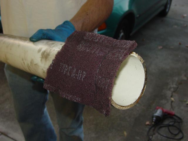
I tore the scotchbrite pad in half and drilled a couple of holes in the end of the PVC to wire it in place. I then stood the TT in a pan of mineral spirits and rammed the cleaning tool up and down inside of it, rotating it as I went. I flipped it over and repeated the process. When it looked like it was as clean as it was going to get, I put a little extra elbow grease into the rusted area until the rust was more of a discoloration than a layer of crud, then rinsed the inside of the TT thoroughly with brake cleaner. Constantine just used brake cleaner, but I had the mineral spirits handy so I used them.
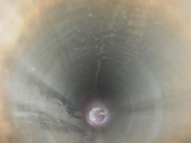
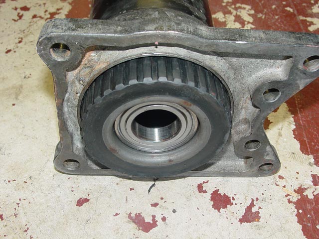
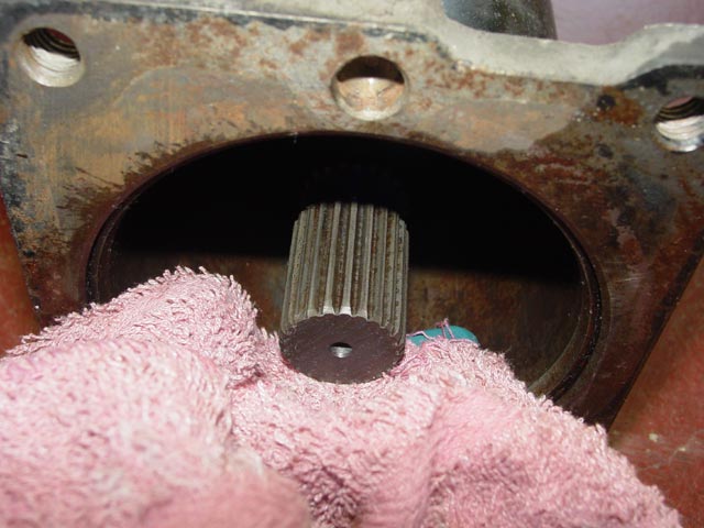
Here is the rust discoloration that was left in the end of the torque tube.
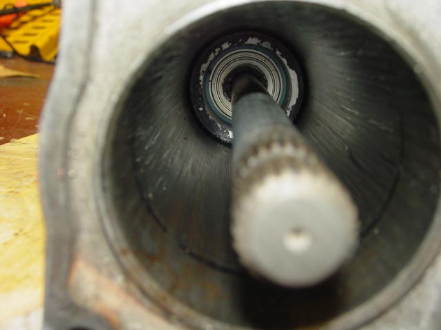
The bore of the tube was very clean. It's essential that the inside be smooth with no gunk and no protrusions of any kind.
The final preparation step was to get a thin coat of oil on the inside of the tube. I sprayed the WD-40 on a rag wrapped around a spray can and shoved it through with my cleaning tool(sans scotchbrite). I had to repeat a couple times to get a thin, even film of WD-40 throughout the inside of the tube. It should not be wet with WD-40, just a minimal film to prevent corrosion.
The first step in assembly was to determine where the center bearing would go. On three-bearing setups, the aluminum carrier goes in the middle and the steel carriers go at the ends Using a tape measure, I located the aluminum carrier in the exact center of the tube then marked the 3' PVC section so I would know when it was in position.
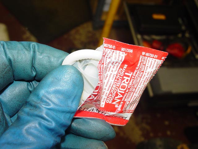
OK, now for the moment you've all been waiting for... here's WTF the KY Jelly is for.
 Constantine came up with the KY approach because it is very slippery but dries to a sticky consistency. Unlike the grease used by the manufacturer, this stuff gets harder to move as time goes on, yet when it's time to rebuild the TT later a bit of water in the tube should release them.
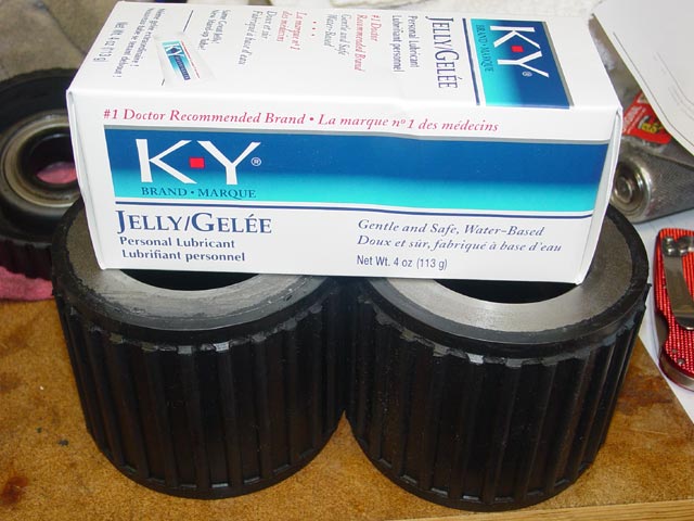
I gave the outside of the carriers a nice thick coat of KY.
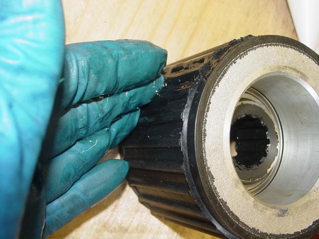
Now is the time to lubricate the inner bushings as well -- they won't be reachable in a minute.
I also gave the inside of the TT a nice wipe of KY.
I placed the aluminum carrier with the inner bushing "hat" facing down on my trusty piece of plywood. It's important to note that the inner bushings should all face the same way. I then set the torque tube over the top of the carrier and pressed down. It took a firm push, but nothing too drastic.
I then used the PVC to push the carrier into position. I had to tap it a little, dropping the TT a couple of inches onto the PVC while pushing down. It took me about two minutes to get the center carrier in, but I wasn't pounding nearly as hard as I had on the old carriers when removing them.
Next, I marked the PVC for the 12" insertion depth of the end carriers.
Overall, the end carriers went in easier than the center one -- I guess that the lube became a little thin as it neared the center. Remember to orient them all the same way!
Carriers inserted, looking at the rear of the tube. The drive shaft gets inserted from this end, so that the force on the inner bushing from pushing the driveshaft in is bearing against the inner race via the "hat" instead of via the circlip.
This is a crucial step so that the driveshaft goes in straight without putting an angular load on the bearings. First, I knocked the inner bushing out of one of the old carriers.
Then I inserted the old carrier into the tube on the side where I would be inserting the drive shaft. Not too far, just enough so that it would stay put.
Next step, tear open the package, being careful not to damage the contents.
Place the condom on the tip of the shaft...
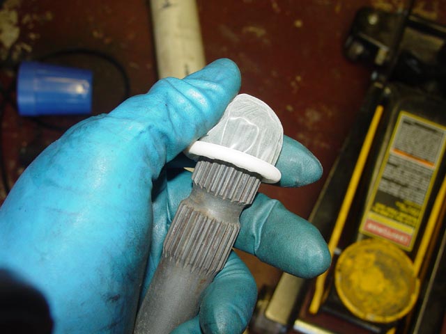
...and roll it down over the shaft.
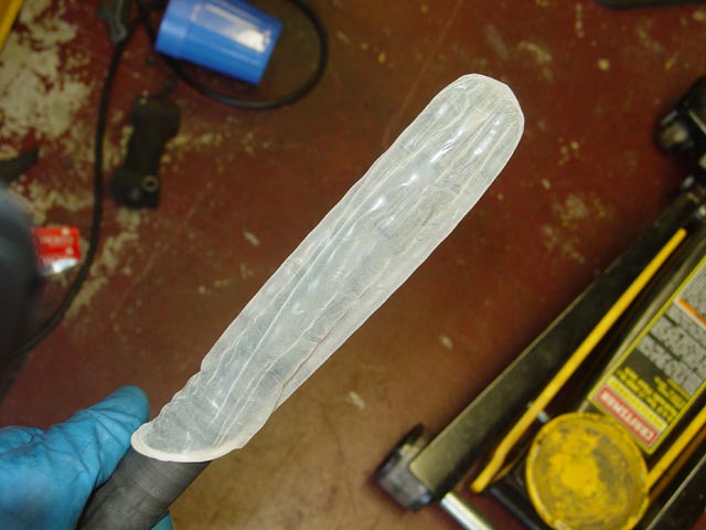
Oops... got a little distracted there, must have been all of that KY jelly...
 Er yeah... soooo... then I lubed the shaft, all of it except the front spline and the last foot or so at the rear with a liberal coat of KY jelly.... trying not to snicker...
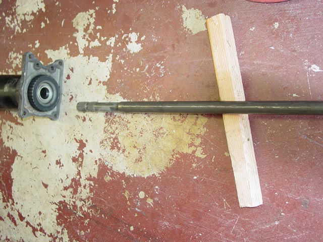
Then I lined up the shaft as close as possible with the centerline of the torque tube and eased it in(so to speak). It took a moment to get it started through the first carrier, and it was a bit more fiddly getting it lined up with the second carrier. I was able to get it pushed in far enough to fully engage the middle carrier just by pushing firmly with one hand while holding the torque tube with the other hand. At this point I simply upended the torque tube, placed the end of the driveshaft on a piece of plywood, and lowered the tube onto the shaft. I had to press downward a bit, but not much.
I was careful to stop a bit short of where I needed the shaft to be, then tapped it the rest of the way into its final position with the deadblow hammer.
Finally, I popped the old carrier off the end of the tube. Mission accomplished!
I verified that the carriers had not moved, and that the shaft turned without runout.
Next I took a wet rag and cleaned the KY off of the front splines. There wasn't a lot on there so it came off easily.
Next I fiddled with some wooden blocks, arranging them under the torque tube and transmission until I found a setup that would align the two pieces without putting any strain on the input shaft or the driveshaft. Remember, If these twist against each other the input shaft can snap.
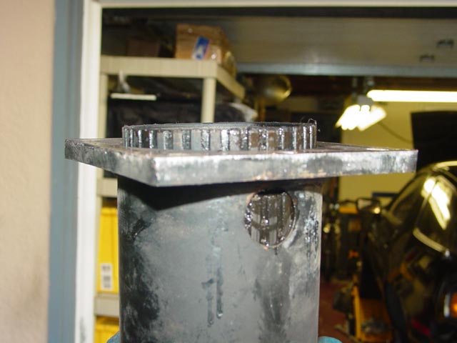
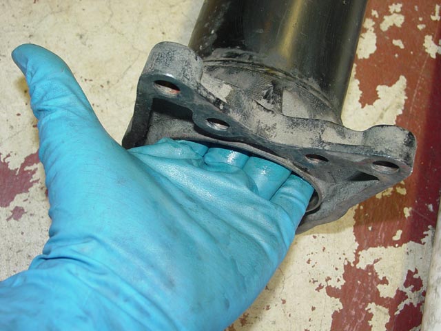
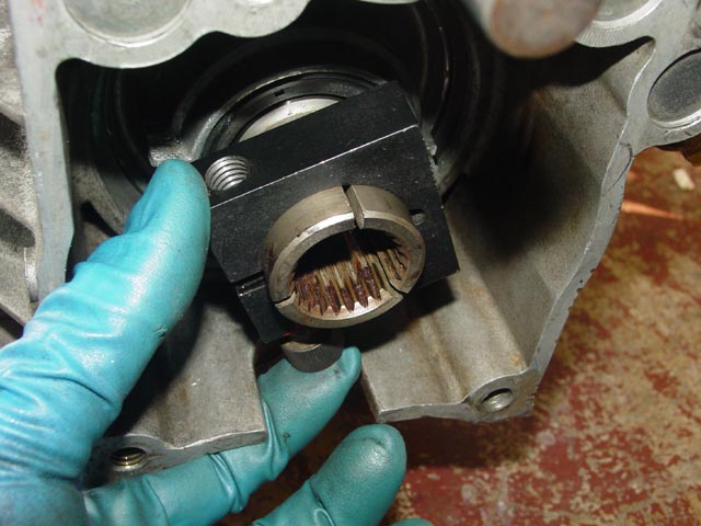
These three sections of the collar are the parts that can snap if too much weight is hung from them. Since there are no dowels locating the torque tube and transmission to one another, some care is called for. Also note the groove in the collar. This is where the pinch bolt passes through once it is lined up with the groove in the drive shaft. I rotated the input shaft so the groove was lined up with the access hole in the bottom of the transmission.
I used the collar and an old bolt to make sure I had it lined up, then I shifted the transmission into gear to hold it there.
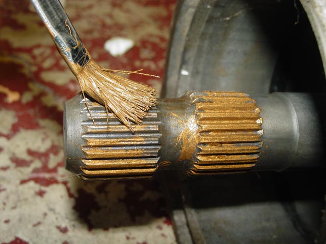
The WSM calls for a coat of Optimoly on the rear spline, so I gave it a thin coat.
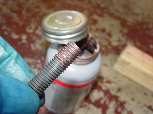
I prepped the TT-to-Trans bolts with some copper anti-seize. Optimoly is called for here as well, but I use the cheaper anti-seize in less-critical locations like this.
I carefully engaged the shaft with the input shaft and slid them together.
It takes a bit of force to engage the splines, so rather than wrestle with it and possibly knock the assembly off of the wooden blocks, I used two bolts to pull the pieces together.
Once the two bolts were snug, I applied anti-seize to the new pinch bolt and installed it finger tight. It would be torqued down later, after the front coupler was installed.
I installed the remaining 4 flange bolts and torqued all six to spec.
Here is a look at the inner bushing that I knocked out of the carrier.
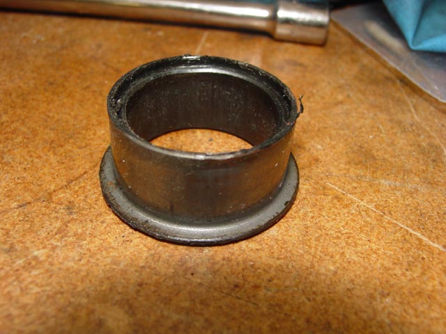
The plastic was coming loose from the steel. I can see now why this part is not always reusable.
With that, I was ready for the next step, setting up the shift linkage. I had been thinking that rebuilding the torque tube would be a big pain in the ass, but as it turned out it wasn't bad at all. And, with Constantine's parts in there, it should be a long time before I have to go in there again.