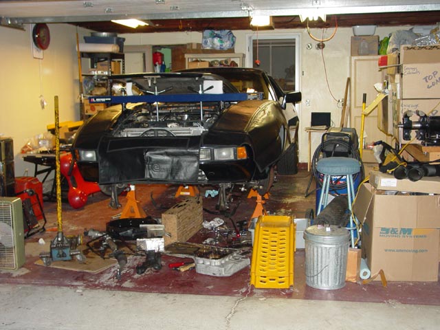
Well, it all started with a trail of PS fluid...
 I had known for a couple years that the pan gasket needed attention -- I had snugged it up in my first months of ownership and saw that the original cork gasket was completely collapsed. I stopped the oil dripping by tightening the pan bolts, but I knew that I had only bought time. So that had been floating around the back of my mind for some time as a "one of these days" project when I noticed an occasional drip of PS fluid. I checked it out and found a couple tablespoons of ATF in the driver side boot. I drove it to and from work for a couple of days after cleaning out the boot and checked it again -- definitely a leak, there was probably 1/2 tsp. of fluid in the boot.
 So, I figured that since I had to have the rack out, I might as well install Carl's solid bushing kit. Upon further reflection, I thought -- hey, just a few more bolts and I can get to the pan gasket, and motor mounts while I'm in there. The car will have to be aligned anyway, why not do it all in one shot? So I ordered up the rack, 3 boots(in case I tore one during assembly), rack stops, Carl's oil pan stud kit, a silicone gasket, and a new set of motor mounts. I spread my purchases among the Big 4, which at the time was 928 International, 928 Specialists, Devek, and 928 Motorsports. I decided to put the front engine shock system to rights as well -- there was one shock still on the car but it was in bad shape.
A few days after I ordered everything, I was pulling into a parking space at work and when I got out I saw a big trail looking like it led to my parking spot. I had a bad feeling about that... I looked and sure enough, there was a puddle and PS fluid leaking from multiple spots. Not much I could do about it other than shove a flattened cardboard box under it and go in to work. When I came out at the end of the day, I double-checked the belt, decided it was just worn enough to merit replacing, and I cut it for the short(<5mi) drive home to save the pump. Nothing left to do but wait for parts, which arrived just before the weekend.
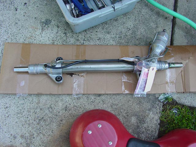
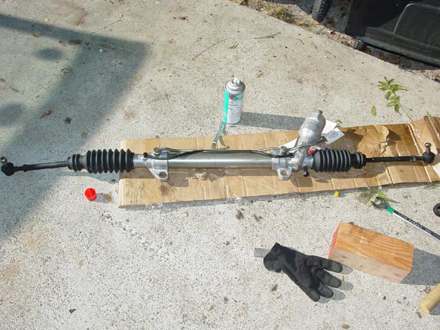
So here's the shiny rebuilt rack:
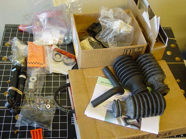
Here are most of the other parts that went into the job.
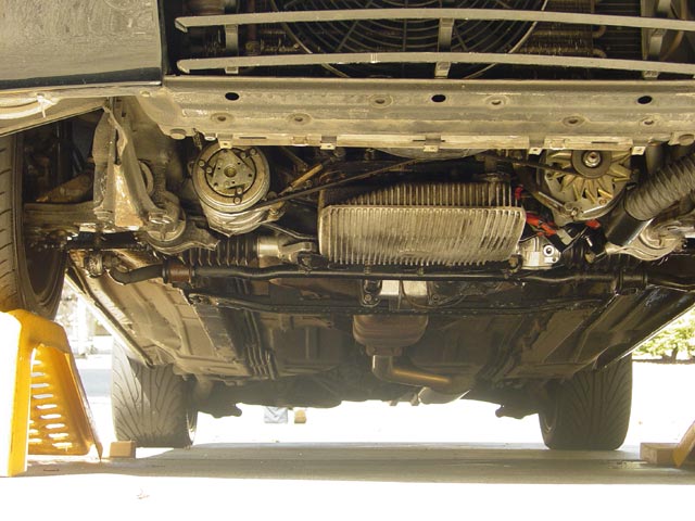
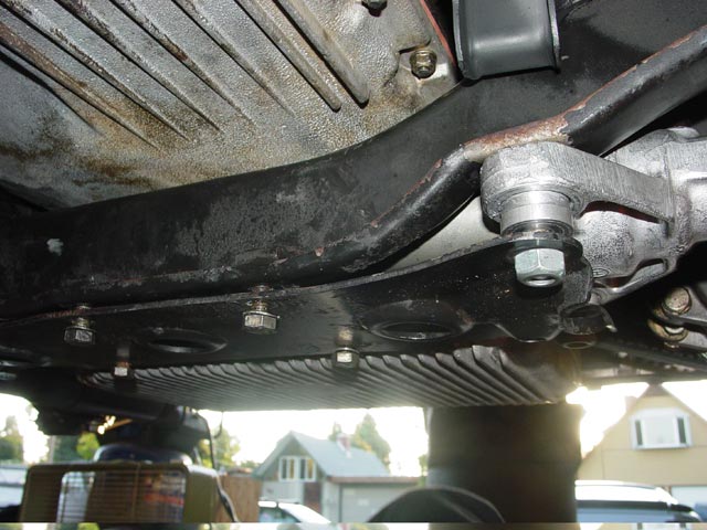
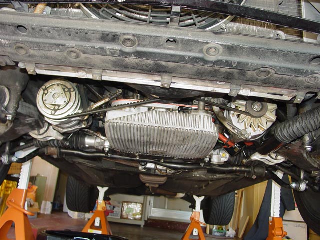
First thing was to pull off the belly pan and clean up the underbelly, which was a mess from the PS fluid dumping out.
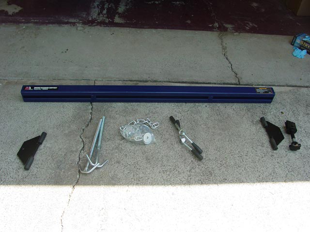
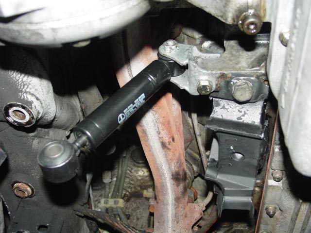
Here is the engine support bar that I bought from Carl(at the lower price...). It's a very sturdy unit and was a big help, keeping the engine secure while I worked underneath.
An even bigger help was my friendly neighbor, Ron Halfhill. He came dressed for the job, with a big smile and Porsche-labeled coveralls. Let me just pause a minute here and say thanks Ron, for the tremendous help with the job, carting the crossmember and pan to the car wash to remove 30 years of caked on gunk, and for the great conversation and company throughout. I know you don't drink, but
 all the same.
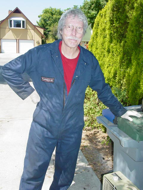
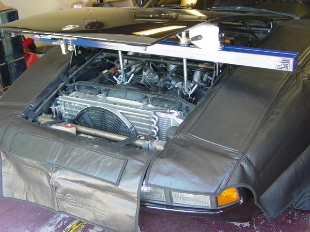
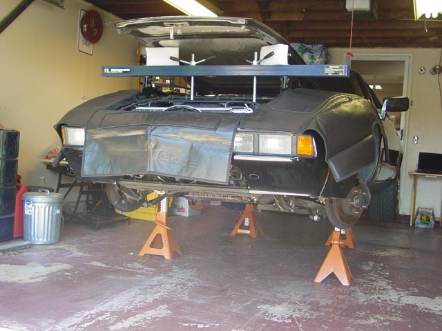
First order of business was to get the engine properly supported while the car was still close to the ground and everything was easy to get to. I set the chains on the AC and PS brackets, since there was no easy way to get the support attached to the diagonally opposed upper lift points. I put just enough tension on it to lift the engine a couple mm relative to the cross brace.
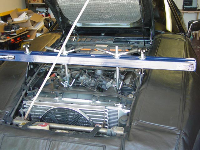
I closed the hood down onto some styrofoam blocks sandwiched between the hood and the support bar so that the uprights on the bar would not dig into the hood liner or ding the hood from the inside. I couldn't have the hood all the way open, since with the car on jackstands the garage door would run into it.
I wanted lots of room to work under the car, so I bought a set of the large 6-ton HF jackstands and this big block of wood in preparation for the job. When this pic was taken, the car was as high as I could get it with the jack alone; the block of wood helped a lot. I would have preferred a wider/longer piece, but that would have cost me $75+. This piece was in the scrap bin and only cost me $10.
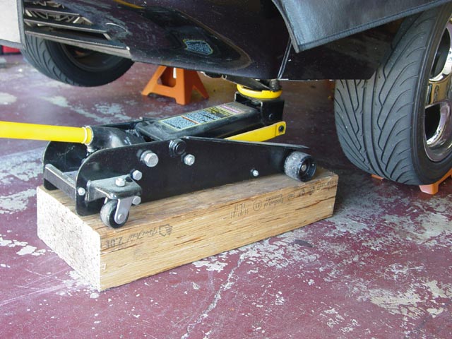
I could have raised it further, but this seemed like plenty of room.
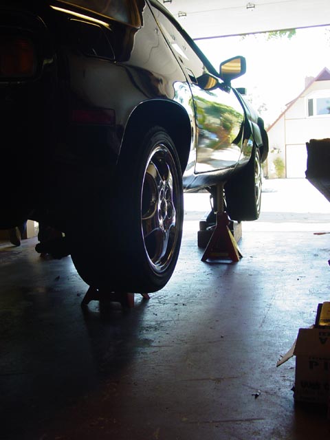
With the wheels off, it looks like there's enough room for a picnic in there.
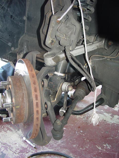
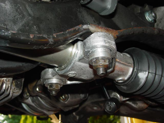
I removed the calipers and tied them up out of the way. The tie rod ends came right off with the help of a puller.
I started the oil draining and pulled the swaybar off. A borrowed compressor and air tools really sped this part of the job up a lot. Note to self -- get air compressor and air tools...
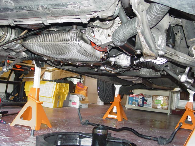
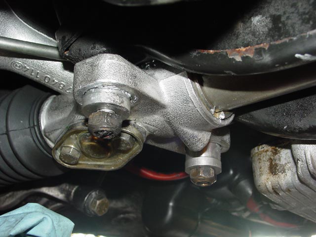
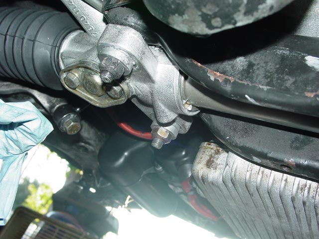
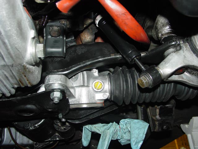
Next I removed the PS hoses from the rack, removed the lower plate from under the rack, and disconnected the one remaining engine shock. After removing the plate I threaded two nuts back in place then loosened the steering coupling from the top side of the rack, at which point I removed the mounting nuts and guided the rack downward as I pried gently between the rack housing and the coupler to free the coupler. This is really all there is to removing the steering rack. Very simple.
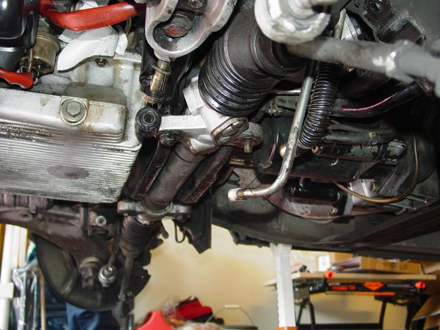
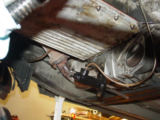
Here is where the fluid came spewing out that day at work. This crossover hose fitting just gave up the ghost. No wonder there was such a huge mess... from the look of things it had been seeping for a while before it let go.
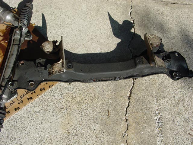
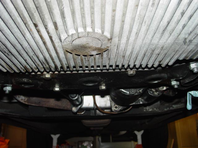
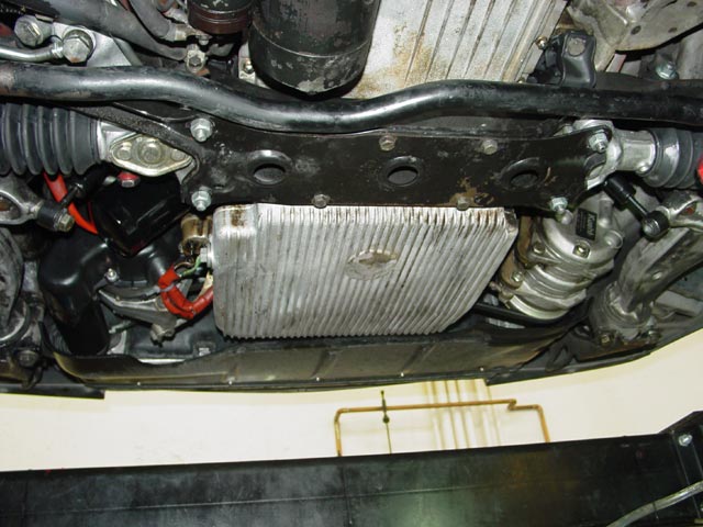
The next step was to drop the crossmember. The order in which you remove hardware is not critical, but IMHO removing the one rearmost 12mm bolt on each side last makes it relatively easy to deal with, as those bolts are very easy to access and do not hold other stuff in place, e.g. the rear a-arm bushing caps. First I removed the bolts on the front a-arm bushings and loosened the hardware on the tie-down loops so I could rotate them downward out of the way. Then I removed the horizontal tie bolts(just outboard of the heatshields) and the bolts that go through the crossmember into the engine mounts. Later cars have nuts here instead of bolts. Next I removed the rear a-arm bushing caps, and the bracket that holds the wiring harness to the crossmember, and finally the rearmost 12mm bolts. At this point the crossmember -- and about 10 pounds of gunk that was attached to it -- dropped right out.
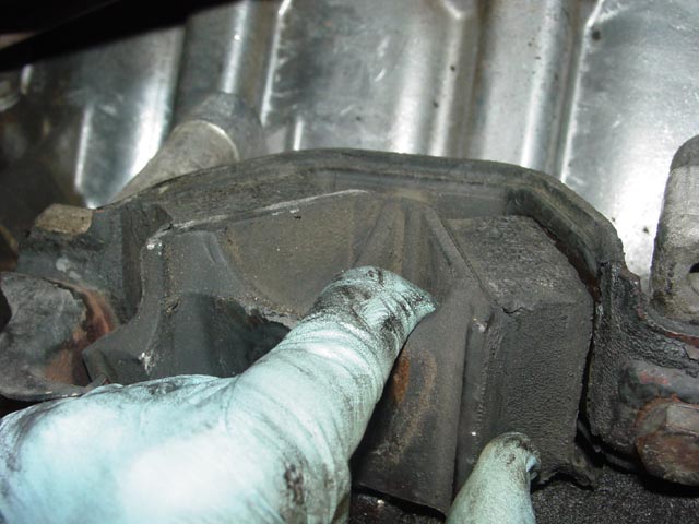
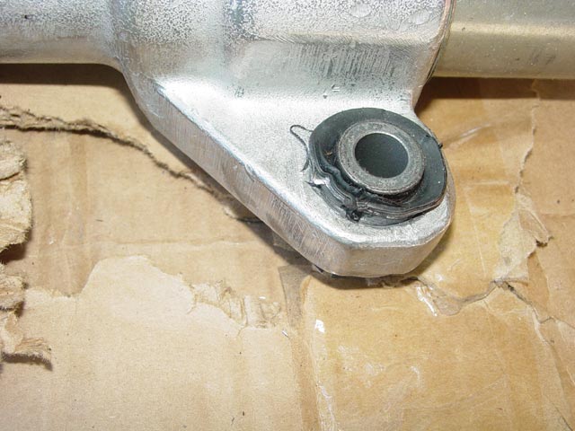
At this point, I checked the engine mounts. Driver side, FUBAR.
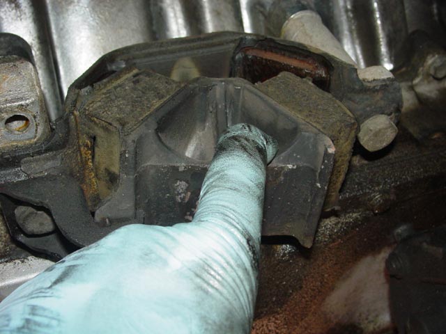
Passenger Side, FUBAR. The mounts are the same P/N on each side. It's interesting to note that on both sides, the mount only let go on the half without a safety hook.
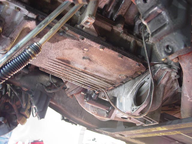
With the toasted mounts off, it was time to get started on the oil pan. Although I only had to pull the starter to get the pan off, in the end I had to pull the clutch slave to get it back on, because there wasn't enough room to maneuver the pan past the slave and over the studs. I'd recommend that you don't remove the clutch slave until you have to, so you reduce the risk of the slave cylinder rod/piston popping out.
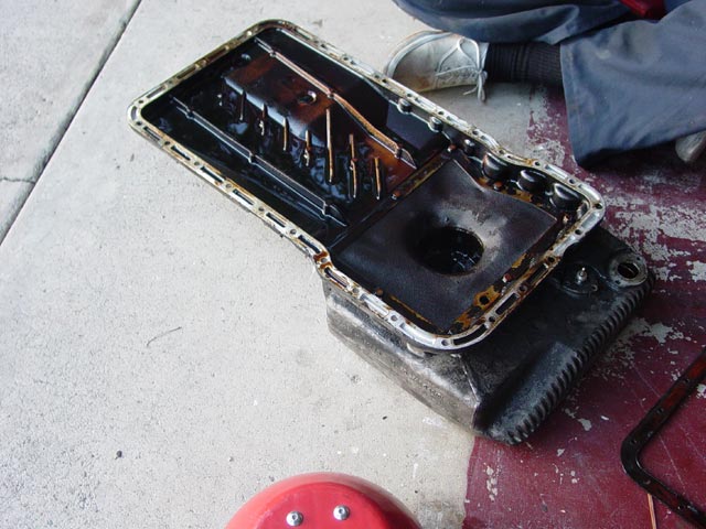
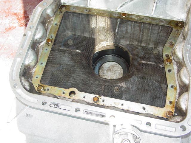
After quite a bit of fiddling, the pan finally came off. Some of the bolts at the front of the pan are very tricky to get to, especially around the oil tube and the level sender. A gearwrench is a must. I recommend that you choose two bolts at the rear corners of the pan and one easy-to-reach bolt on each side near the front of the pan and leave them till last. Loosen each of these last bolts a turn or two, then you will be able to easily hold the pan in place with one hand while you remove the last bolts with the other. Hopefully, the inside of your engine is cleaner than this. I'll have to take steps to clean it up, like ATF flushes at each oil change.
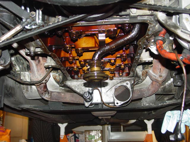
The inside of the block was marginally cleaner, giving me hope that it would eventually clean up with some TLC.
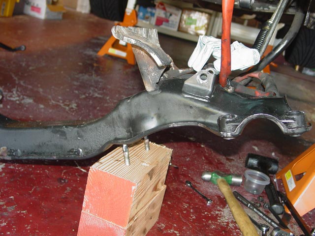
With Ron's help, I took the crossmember and oil pan to the car wash and cleaned maybe 90% of the crud off. Some of it was petrified and wouldn't move, so I left it. This car is a daily driver, after all. Then it was time to close up shop for the day. Note the workbench still buried in moving boxes...

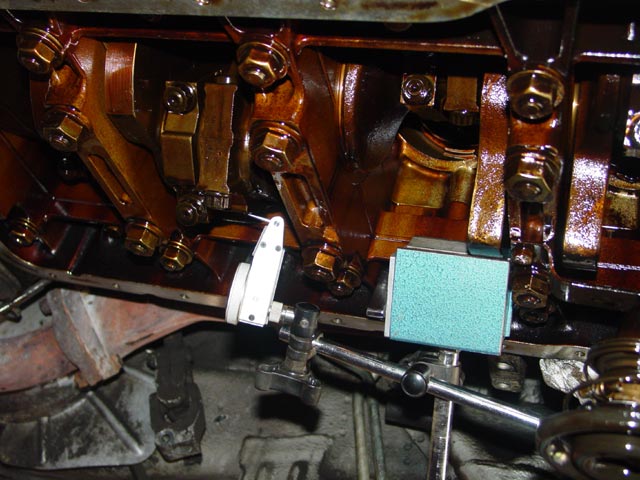
I checked for play in the rod bearings. Found less than 0.0005". I know that this isn't really the right way to check but I had already scheduled the time to do the job and Ron's help. Removing the rod bearing caps to use plastigage would have involved replacing the hardware, and when that was suggested to me I didn't have time to source the bearings + hardware before the project weekend. This was just a check to see if they were real bad, in which case I would have taken the appropriate action.
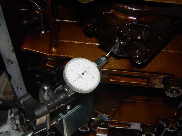
A better view of the setup, showing that I was measuring on the correct axis at least...
I installed all of the oil pan studs with blue loctite after cleaning up the sealing surface and spraying out the holes with Berryman's and blowing them dry with compressed air. Anyone who has issues getting nuts on all of the studs, or uses some of the factory bolts for whatever reason, is apparently using the wrong set of studs and/or nuts. I had no issues getting the nuts over the front row of studs.
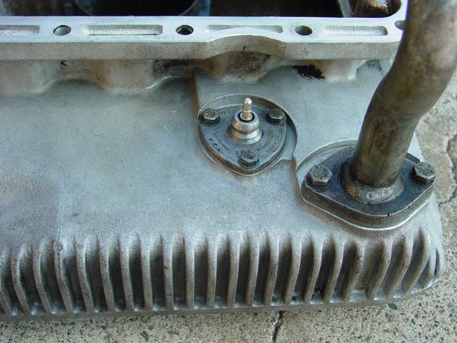
I also replaced the gasket on the level sender and the O-ring on the oil tube.
I thoroughly cleaned the oil pan and screen before reassembly.
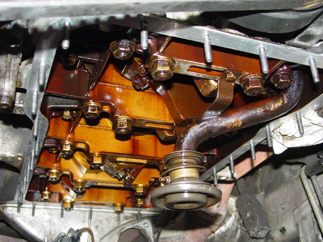
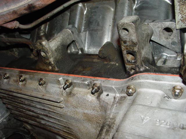
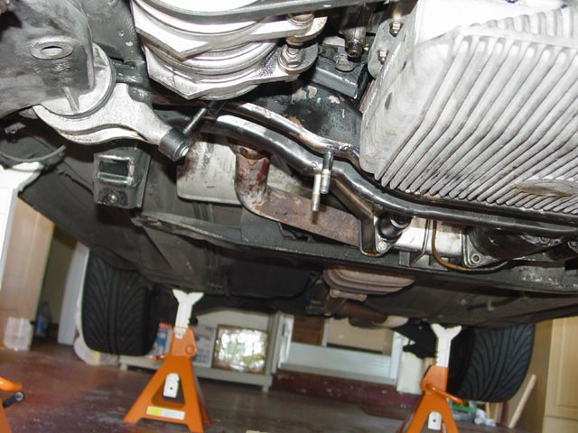
Oil pan in place with the new gasket. As I mentioned before, the clutch slave had to come out for this step. Once the pan was in, I reattached the clutch slave.
A peek at the gasket from another angle. Yes, it's dirty above the gasket, but that's from old leaks, long since fixed. As of this writing, over a year later, the gasket is still clean.
After installing the new motor mounts, these two studs on each side looked like they would end up a bit close to the crossmember for comfort, so I trimmed them.
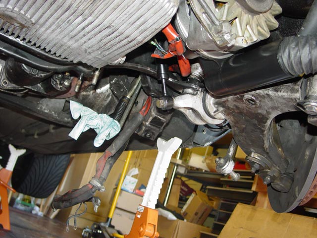
This seemed like a good time to install the engine mount shocks, so I did...
I propped the crossmember up so the harness would reach, and reattached the harness.
Next I lifted the crossmember into place and held it with one bolt threaded a couple turns on each side while I lined up and installed the rest of the hardware. Only after getting all fasteners threaded in a few turns, I snugged them all by hand, tightened them just a bit, then circled back around and torqued them to spec per the WSM(after the car was back on the ground).
I had overlooked this shock bolt when gathering parts, and took this pic to remind myself. Drove the car for a few days like this with no issues, but I could tell the difference between one good shock and two good shocks. It would be hard to say how much difference the one good one made vs the one old one, because the motor mounts were changed at the same time.
This is where I cut off the studs because of my concerns about clearance. The tip of the stud looked to be within ~3/16" of the crossmember, and I was afraid that they might contact the crossmember either now or as the mounts age. Carl assures me it's not an issue, and he's probably right but I wanted to be doubly sure.
With that out of the way, the remaining work is just the second half of a typical rack R&R. Well, mostly.
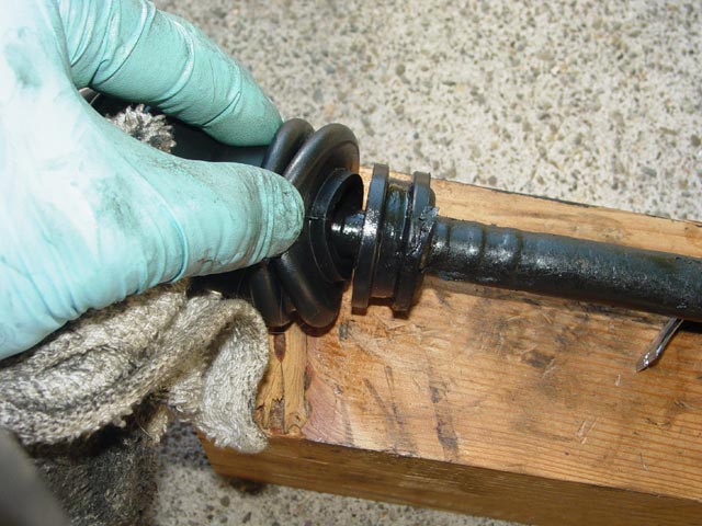
I added Carl's solid rack bushings and there are a few details that a shop wouldn't bother with but I decided to address them. Below, an early attempt at removing a rack bushing. I have done a couple of racks now, and I'll tell you about my method in a second. I've heard that it's easy to fold the swaged edge of the bushing up and push it through the rack ear, as I was trying to do in the pic below. I wasn't having a lot of luck with that approach. What I've found works for me is to get a small drill bit (about 2mm) that would drill through the rubber without binding on the inner or outer metal collars. I drilled a series of holes around the rubber, finishing by running the drill around the rubber area to rip most of it loose. Then, using a large pair of channellocks, I grabbed the inner steel bushing and yanked it out. Then I was able to grab the edge of the outer bushing with the channellocks and twist, reducing the OD enough to pull it through the rack ear. Sorry, no pics of that procedure, I'll get some next time I help someone do this.
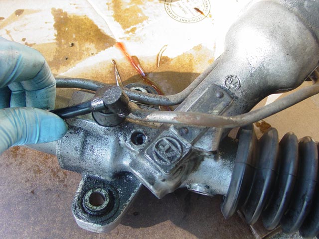
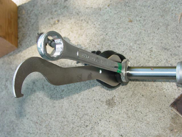
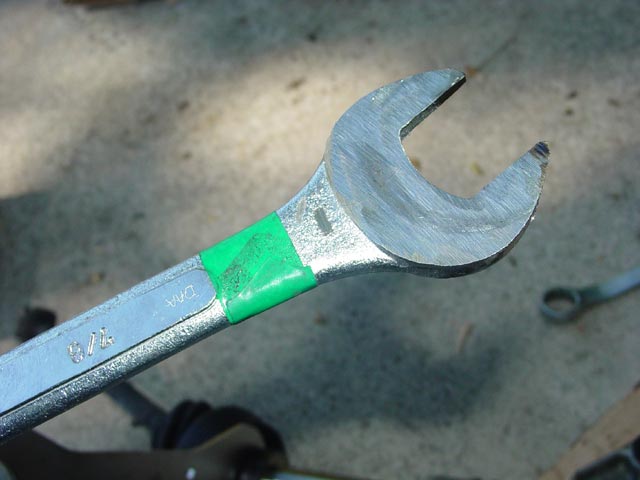
I removed the tie rod ends using two wrenches lined up so I could squeeze them together to loosen the threads. One was a 32mm bicycle headset wrench and the other was a ground-down cheapo 7/8" combination wrench. I understand that an unmodified wrench would work on the later cars by simply sliding the stops inward along the rack shaft. The rack stops are held captive on the early setup. The stops engage with the flats on the rack and cannot be slid inward on the rack. You can see this feature on the replacement stops, in the second pic on this page, a bit above and left of center.
I had to grind slowly to avoid overheating the wrench and ruining the heat treating.
This was one of the toughest parts of the job -- getting the rack boots over the rubber flanges on the tie rod ends. It took a little silicone spray and a lot of cussing to get the narrow end of the boot properly engaged on there.
Here is the rack, ready to go in, centering bolt in place. I measured the length of the old & new rack, and having determined that they were the same length I just moved the tie rod ends over to the new rack. I had no intentions of driving far without an alignment so I felt this was close enough.
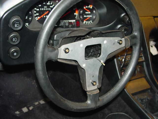
This is one of those details that not everyone cares about. Of course I wanted the wheel to be centered with the centering bolt installed in the rack, but additionally I wanted the wheel to lock in the centered position when the key is taken out of the ignition. So, with the column locked, the wheel was about 30� off-center. I removed the wheel and centered it on the locked column. If you consider this step a waste of time, so be it -- but I only "wasted" about 5 minutes doing it.
I positioned the rack on the studs protruding from the crossmember(later cars have bolts instead of studs), put the solid bushings in place with a smear of anti-seize, and threaded the original nuts on just enough to hold it in position. Note that these nuts are supposed to be one-time use. Once they have been installed and removed, they should be discarded since they will not lock as designed with multiple uses. So, for the next few steps, I used the old nuts. Don't tighten them yet! The solid bushings are a tight fit, so tight I had to scrape the paint from the studs so they wouldn't be a press fit, and will be difficult to remove once they have all been pulled into the rack ears. Of course, if you are using the original rubber bushings, this is not an issue -- in that case the rack may be removed easily during the next step if you choose to concern yourself with wheel centering to the same degree that I did.
At this point I found that I had to do some fiddling to get the wheel to line up properly. There is a cutout on the rack input shaft to provide clearance for the pinch bolt on the coupler. So, the coupler only goes on the shaft one way, or at best you may be able to move it a spline either way. Unfortunately, rebuilders tend to reinstall the input shaft in a random orientation when they put the rack back together. I have been told that this is not an issue on later cars because the bolt hole is drilled differently on later cars and aligns with a different groove that goes all the way around the input shaft -- allowing you to mount it however you wish. As far as I can tell from PET, the same coupler is used on all cars, so the best advice I can offer is to look at your setup once you have it apart.
What I had to do was get everything positioned and get the wheel/coupler/input shaft lined up the way I wanted it, then dremel a new groove in the input shaft to clear the bolt. I misspoke above, the rack boot wasn't that tough -- this part was a huge PITA because there is so little room to work in there.
I think I had the rack in and out a half-dozen times trying to get this right. Again -- don't tighten up the nuts yet, or you'll be sorry! If you don't care about the wheel locking in the straight-ahead position, this may not matter -- what most shops and DIY'ers do is just get the coupler on the input shaft, then, with the centering bolt in the rack, reposition the wheel on the column. Beware though, the rack input shaft and the steering column have a different number of splines on them and the wheel might not line up perfectly. This is the way Devek left my car set up after my first alignment, when I had the aluminum ball joints replaced -- half a spline tooth off-center. 
Having centered everything to my satisfaction, I proceeded to use the old nuts to pull the rack mounting bushings into the rack ears. If you like, you can use spacers with an ID slightly larger than the solid rack bushings and perhaps 5mm thick(I could measure if anyone cares) to ensure that the rack is sandwiched tight against the crossmember. You may notice that the bushings did not all pull up evenly. However, the rack is held very tightly in place -- it didn't move when I removed the nuts subsequent to taking the below pics, and they have not moved in ~10K miles since. Well, actually, I had the rack out after this, I'll explain at the end. But since I finished fooling with it, it has stayed put.
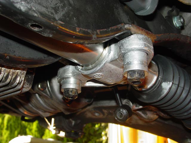
Next, I removed the old nuts. The rack did not move at all because of the slight interference fit -- the studs/bushings/ears are in tension because of slight manufacturing variances in the crossmember. This may not be the case if your crossmember has bolts rather than studs -- watch your head! The next step was to install the bottom plate and associated hardware, including new locknuts...
...then torque to spec. Next I wired and hung the starter...
At this point it was all straightforward reassembly. I reattached the tie rod ends to the knuckles, again with new locknuts. I reinstalled the swaybar, also with new locknuts on the drop links. The PS pressure hose was reinstalled with new crush washers, the return hose I installed with the old crush washers(you'll understand why in a minute...).
At this point, everything is buttoned up and ready for fluids. I filled the crankcase with fresh oil, and filled the PS reservoir with fresh Dexron ATF. The rack comes with instructions to flush the system thoroughly upon installation. Below is the procedure that I used. Maybe a bit overkill, but it only used about 3-1/2 quarts of fluid.
- Fill reservoir
- Start engine, keep adding fluid until level stabilizes.
- Turn wheel lock-to-lock once, top up fluid as needed.
- Turn wheel lock-to-lock 10 times in each direction.
- Turn off engine.
- Remove PS return line from rack, allow system to drain.
- With return line off, turn wheel lock-to-lock repeatedly until fluid is no longer flowing out(slow drip, rack makes sucking sounds when moved)
- Reattach PS return line to rack
- Repeat steps 1-8 two more times
OK, at this point you would think that, having done everything right, all that was needed was an alignment to top this off with a happy ending. Unfortunately, such was not the case. The rebuilt rack was leaking from the input shaft seal.

Don't let this scare you off. If anything, this only reinforces the importance of dealing with top-notch suppliers. I bought the rack from 928 International, and they offered me two eminently fair options: (1), send the rack back and they would send out a replacement. (2), Buy another rack for immediate shipment and receive a credit when the defective rack is received by them. I chose option (2) to minimize downtime. Some may argue that they ought to have sent another rack right away without charging, but they have to protect their interests. Even though they recognize that I am a good customer, a rebuilt rack is an expensive thing to just send out based on a phone call, relying on the good will of the customer to send back the old rack. IMHO they handled the situation professionally and fairly, essentially on a no-questions-asked basis.
It's unfortunate that I had to R&R the rack AGAIN, fight to get the solid bushings out, dremel the input shaft AGAIN, flush the system AGAIN(only 2x this time around), replace all of the locknuts AGAIN, but considering the number of vendors out there that would have happily left me high and dry(not referring to any of the Big 5 or however many it is now) I couldn't ask for better service.
So.wouldn't you know it... I finish the job, the new rack is, if anything, tighter than the previous one, and after a couple of short runs to settle the suspension and verifying that all is bone dry underneath... I take it to Devek to get the alignment set, up it goes on the lift, and what do I see but PS fluid dripping off of the alternator shroud and the oil filter!

We quickly determined that the problem was that the PS pump was leaking from the rear housing seal. We went ahead and finished the alignment and I ordered the seal kit. I was glad that it turned out to be minor, and I was especially glad that it wasn't the rack.
 As you may have guessed, next weekend's project is Resealing the PS Pump.
I want to thank Ron again for all of his help, and for the great conversation and philisophical discussion... as well as the understanding on the occasions that I would just sort of look at some feature of the shark's underbelly, appreciating it. Thanks Ron!
