I've been taking more time to focus on my AC now that I have the more crucial items out of the way. I have spent quite a bit of time reading up on AC in the 928. I was quite familiar with how AC works, in theory. The specifics of how it's implemented on the 928 required some study though. Again, I ran into that maddening problem whereby there is info aplenty for the later cars, but very little info specific to the 78-79 is available. I had to make my best guess as to whether the problem I was having with the "Speed Relay" or elsewhere. Finally a post to Rennlist yielded a response from Wally Plumley that clarified some things for me, confirmed my guesses, and gave me some pointers on where else to check.
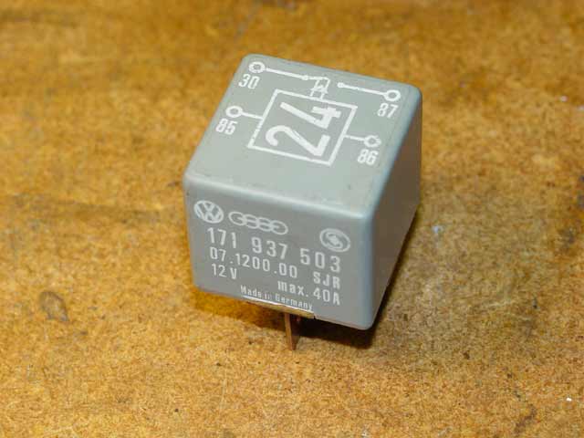
Basically the 78 and 79 cars incorporated a speed relay intended to prevent the AC clutch from engaging unless the engine is running. This reduces the electrical and mechanical load during cranking in the event that the HVAC head is in a position that calls for cooling while starting the engine. Later cars have a separate pushbutton to activate the AC, but in the early cars the circuit is activated when the slider is in either the AC or Defrost position. I don't know for sure, but I'm guessing that the later cars provide the "engage AC clutch only if running" functionality via one of the brains rather than with a speed relay.
I had seen the AC clutch engage on the car before; the AC had blown cold when I inspected the car for the first time(PO must have just charged it
 ). By the time the car came back from Reitmeir's, it no longer blew cold at all. I checked with them and the mechanic told me he didn't have to break open the AC, he merely laid it aside. He had cleaned things up back while he had my car, and I hadn't seen oil on the hoses or compressor so I thought it might be OK. I dropped the issue for the time being while I fried bigger fish. At the end of June I had some spare time and I went to an AC shop. While I was there we discovered that the AC clutch was no longer engaging so we bypassed the circuit while testing and charging the rest of the system. The tech did a vacuum check and declared the system "tight enough" and he charged it, adding some dye. The AC blew 40°F at the vent sitting in 85° ambient shade, without the fan running. I didn't measure, but it was even colder going down the road. We tested the low pressure switch, the temp switch, and the freeze switch, and they all checked out. The fan came on when the freon became hot enough. I was foolish enough to hope that all I needed to do was trace down the fault and it would quickly be smooth, cool sailing.
I found the correct relay at a dismantler and hooked it up. The compressor spun, and I was happy... until I realized that now the relay was no longer switching OFF when I had the HVAC selector in a position that didn't call for cooling... such as "Off". I posted a question to the Rennlist 928 board(linked above) at about this time but didn't get any responses that really helped before I had to leave on a camping trip. Upon my return I went back to where I picked up the first relay and they let me try another one, which acted the same way.
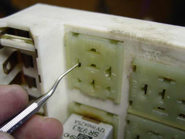
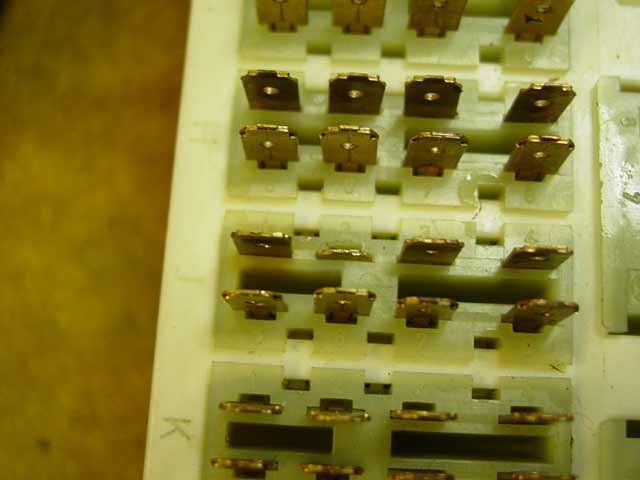
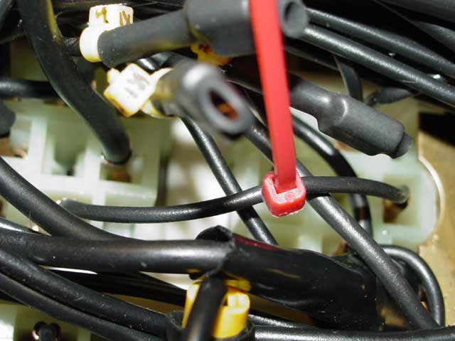
I fooled with it some more, getting nowhere. It wasn't until Wally Plumley pointed out the possibility of PO wiring that I began to realize that just checking the ends of the wires was not going to cut it... I was going to have to trace and inspect every wire involved to find out where the signals were getting mixed up.I traced everything, found no hacked wires in any part of the harness under the hood, or any part of it in the passenger compartment related to AC. I checked and the "AC-on" signal from the control head was arriving at J2 as the expected 12V above ground on that pin, when the selector was in either "AC" or "Defrost" position. Pin 30 on the relay OTOH was always at 12V. I had finally narrowed the problem to this area, internal to the fuse panel(circled in red below):
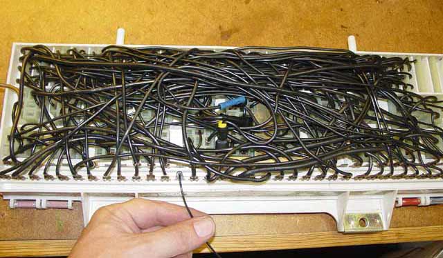
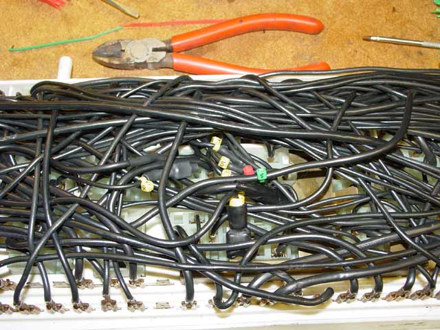
So, finding this it hit me... the butt connector that I found on the back of the fuse panel must be the problem. When I reconditioned the panel I didn't know what this was for, I simply improved the connection from a butt splice to a soldered splice. I went back to look at the pics I took at that time, and it's clear as day on the 2272X1704 version of the following pic from my Bzzzt page... Pin 30 on the relay was hard wired to the yellow connector in the foreground, which goes straight to the main busbar from the battery! No fuse!

As of Thursday the 8th I felt pretty confident that the problem was identified, if not solved yet. That needed to wait till the weekend. The way I read the diagrams(and my meter), what I needed to do was pull the panel and re-establish the connection between pin J2 on the panel and pin 30 on the speed relay, removing the connection to the main busbar. This seems to be one of the more subtle PO wiring hacks I've heard of. As I said above, the AC blew cold when I inspected the car.
I had some time to think about my next move; by now I had a thorough understanding of how the system was supposed to work, and I thought the concept of the speed relay seemed like a very good idea. What I didn't like was the way Porsche chose to execute it. The speed relay is an expensive part that has been discontinued by Porsche and is getting hard to find. It carries the whole load of energizing the AC clutch, which is highly inductive and leads to arcing at the contacts. The relay that no longer worked had a big "arc-mark" on the inside of the case adjacent to the toasted contacts. What's worse, the power that goes through the speed relay to the clutch is provided by the small switch inside the expensive control head, activated by the slider, and it also passes through the freeze switch; these are switches E30 and E33 respectively on the diagram above. So all of those contacts are subject to unreasonably high inductive switching loads. I have heard of people adding a relay to this circuit to take the load off of the HVAC head. Because of availability issues with the speed relay, I resolved to take the load off of it as well, and the freeze switch while I was at it. I decided to modify the circuit so that those 3 sets of contacts would never have to work any harder than necessary to activate the relay below, which in turn draws power from fuse #17(as originally intended) and sends it to the AC clutch when activated:
Here is the revised wire diagram. New power relay is at the top right. This was accomplished by disconnecting some wires from an unused relay socket, then moving one wire and adding one wire. I will make a nicer version of this, including details of how I marked the changes within the panel, and keep one copy in my logbook and another with the car:
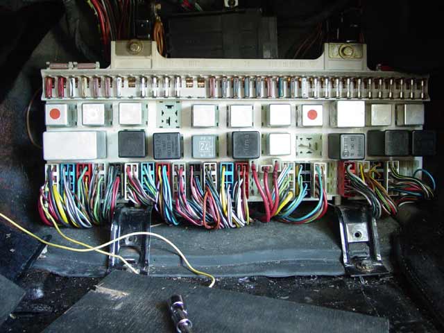
Now, a break from our regularly scheduled programming... I picked up a fuse panel from the dismantler so I could cannibalize it for parts. Replacing burned relay sockets is easy. You just need a tool that will slide in alongside the terminal to disengage the tab, allowing you to push the connector out the back of the socket. I have a dental tool with the hook cut off the end that is perfect for this. For future reference, the relay terminal numbering is as follows for most of the sockets: In the pic below, the bottom left terminal of the socket that I am working on is pin 1. The dental tool is in pin 2. The middle terminals are numbered 3, 4, 5 bottom to top. the ones on the left are 6 on the bottom, and lastly pin 7.
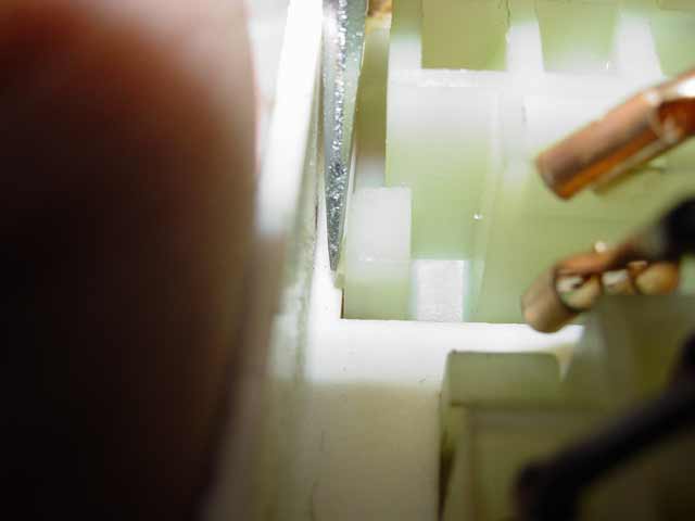
Having removed the connectors, use a small screwdriver to release the 4 tabs on the socket as you push it out toward the front of the panel.
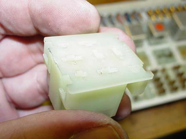
So there it is... one relay socket ready to use wherever needed.
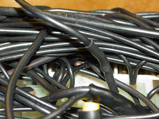
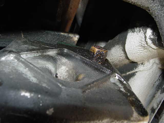
So, on to the fun part... I removed the panel and had it on the bench in less than 10 minutes. Previously, when I had my panel out for reconditioning, I overlooked the cut wire shown below. It was buried under the large bundle of wires, and I only found it this time around because I followed the wire from the J2 connector and I knew what I was looking for. In the foreground is the place where I replaced the butt splice with solder and heat shrink. Obviously the wire was simply snipped and the relay pin connected to the busbar. Lesson learned.... WYAIT, push the wires around and search THOROUGHLY for cut wires, especially if you see that any sort of change has been made to the wiring on the panel. Also, after digging through the spare panel a bit, I'll add that you should look for bubbled or deformed insulation on any wires, which results from overheating. There should be no connectors of any kind on any wires on the backside of the panel, except at the wire ends where they connect to the panel itself.
Rather than solder the wire again, I removed it and replaced the wire from J2 to XI-3 with a good wire from my donor panel. The connector pins have a tab that needs to be depressed just like the relay connectors, whereupon the connector just pushes out toward the back of the panel:
I decided to use the seatbelt relay position for my new power relay. As far as I can tell, the seat belt relay serves no purpose that I care about. I removed four of the wires from the seatbelt relay socket and tagged them with yellow tie-wraps, Each one is marked to indicate which relay and which pin on that relay it was originally connected to. Each tie-wrap has the relay designation and the pin designation marked on two sides with a fine-point Sharpie permanent marker:
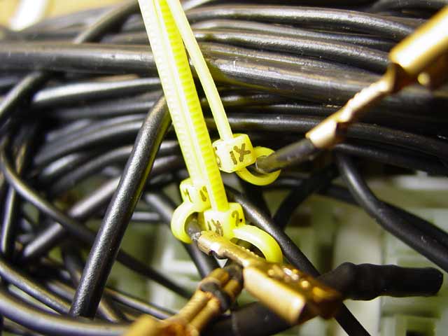
I left the tails on the tie-wraps to help hang on to them while I applied heat-shrink tubing over the connectors, after which I pulled them up tight and clipped the tails:
The one wire that was moved from its original location I tagged with a green tie-wrap and marked with it's original relay designation and pin number, and with the connector pin that it is connected to:
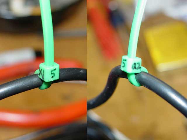
The one wire that was added, I simply tagged with an unmarked red tie-wrap:
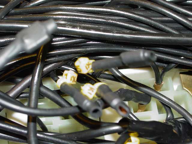
Here is a pic with all of the backside work completed. Anyone looking at this in the future will find it easy to determine what has changed, and with nothing more than the tie-wrap tags and a wiring diagram it should be straightforward to return things to stock if desired. Additionally, as I said above, I will keep documentation with the car and the logbook that will make it trivial for anyone to understand the changes that were made.
Here it is put back together. I think there are very, very few people in the world that could spot my improvement, or even spot that something was changed, just by looking at the panel. The observer would have to know that a special 7-pin relay, not a power relay, belongs in the IX position. I chose this position for two reasons: One, it's right next to the speed relay which controls it. Two, I may eventually find that I have some use for the currently-unused VIII relay position. If I find some day that that is not enough, then I still have the option of utilizing the essentially-unused XV relay position. Hopefully I won't ever have to go there, but I'm not afraid to if it proves necessary.

After all this work I found that much of my freon had leaked out. The expansion valve itself leaks, as do the o-rings for the hose fittings. One of the hoses was beginning to seep oil near the small end of a ferrule. The compressor is leaking out of every seam. The next phase of my AC odyssey will involve replacing the expansion valve and everything forward of it(except the condensor) with the Griffiths Bolt-On Kuehl Compressor Kit. The whole kit with NEW compressor & clutch, new hoses, etc. costs $170 less than just the rebuilt direct replacement compressor with no clutch, the hoses are $147 and $337 IIRC, the dryer is $150... the decision was a no-brainer for me. I am in the process of hunting down the later compressor mounting bracket that I will need. This coming weekend I will be pulling the system out, minimally enough of it that I can get to the one rubber hose that is not included with the Griffiths kit. That hose I will have rebuilt by a local AC shop with barrier hose during the following week. The following weekend I should be able to install all of the new parts, and during the week after that I will get it charged and checked. Watch this space for updates...
Second Assault - July 17, 2004
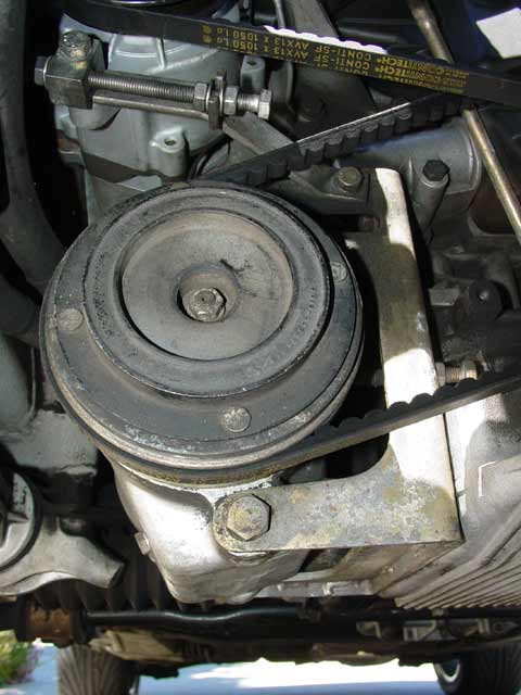
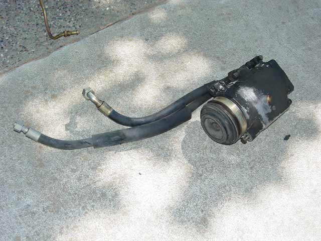
Time to remove all of the parts that I plan to replace, except for the dryer. Mostly I wanted to get the coolant pressure line out so that I could get the rubber portion of the hose upgraded for R-134A. Anything else I can get removed is gravy, that much less work I will have to do next weekend to get the new parts installed. So, I took one last snap of the original compressor in place. Whoops, I've only ordered the newer bracket for the AC. This pic got me wondering, and upon browsing through PET I see that I will need the adjusting strut for the smog pump too. Gotta get that handled Monday...
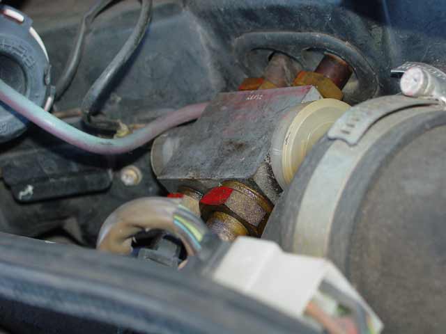
A peek up at the back side of the compressor, showing the leaky relief valve.
And a peek under the rain shield at the leaky expansion valve. You can see here where it has been leaking oil out from under the cap that covers the diaphraghm that controls the valve.
If you attempt this, learn from my mistake... save yourself a lot of time and pull the wiper motor and heater hoses before you attempt to remove the expansion valve. It will help you get tools in there to counter-hold the valve, and it will make it easier to manipulate the bulkhead fitting where the hoses pass into the front tray.
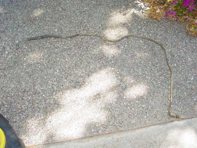
This is the coolant pressure hose, the one that's not included in the Griffith kit. I should have it back, rebuilt with barrier hose, by mid-week.
And here is the compressor, out and useless. It still has a perfectly good clutch and front bearing, and is a working(if leaky) core. Any takers? I'll have a bracket too shortly.
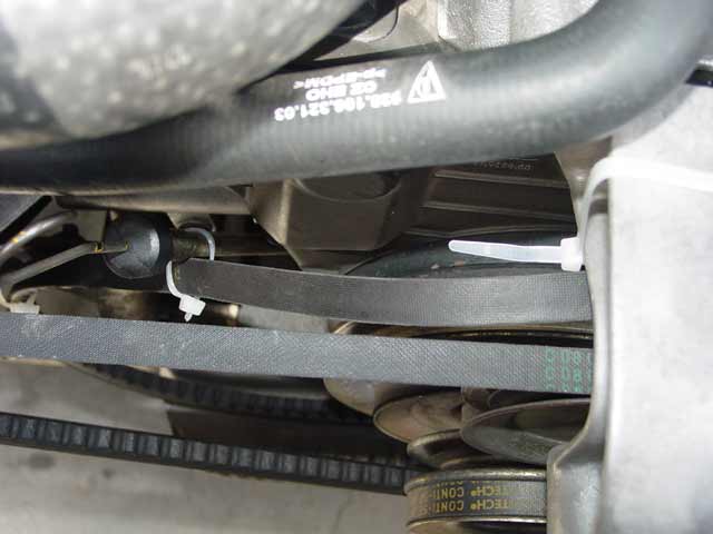
I tie-wrapped the belt up away from other belts and the crank pulley, because I didn't really feel like pulling it out only to have to put it back on the following weekend.
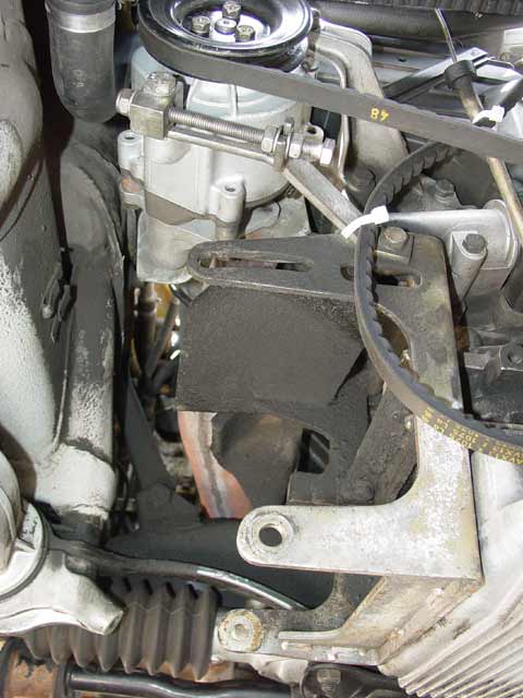
So here is the old bracket, left in place for two reasons... one, to keep the smog pump & cooling fan belt tight, and two, as an additional place to tie-wrap the AC belt.
Here is the new Kuehl compressor from Griffiths. I installed it on Saturday July 24, mileage unrecorded. The mounting kit is top-notch hardware throughout; grade 8.8. The metal adapter plates on the near side of the compressor appear to be about 4x thicker than the original compressor bracket. They are very, very strong. Far stronger than necessary, but I like that.
The compressor is said to be more efficient than the original, and it comes in a much smaller package. Weight of all the parts you see in the pic below, about 171/4 pounds. Weight of the Behr compressor shown above with the two old hoses, about 231/4 pounds. So there's also a 5 pound weight savings, plus the aluminum bracket is about 2 pounds lighter. So my shark has gone on a 7 pound diet with this upgrade!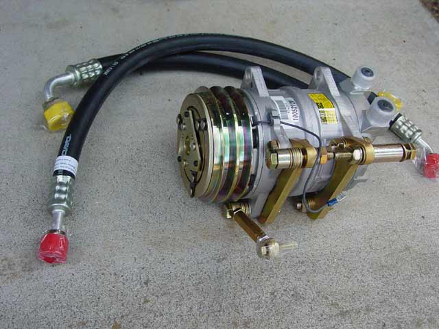
During the part of the job when I was mounting up the later aluminum bracket and the heat shield, I had lent out my digital camera so I didn't get pics. It's pretty straightforward though. Everything bolts right up. If you are upgrading as I was, you will need 4 M8x35 standard bolts to attach the bracket to the block; the original screws will be too short. You will also need the later model tension strut for the smog pump, pictured later down the page. Once I had the bracket in place, I hung the compressor and found that with the spacers shipped with the kit, the front groove on the pulley lined up perfectly with the groove for the AC belt on the crank pulley. So, most of the big pile of washers that they sent as shims to line up the grooves were unnecessary. YMMV.
During the trial fitting it seemed to me that the lowermost pair of unused mounting ears were hanging lower than I'd like. That trial fit occurred while my camera was away, and I got it back just in time to get a snap of the hack job I did removing the ears. I held the compressor in a vise by the steel bracket for this. Much, much cleaner ear removal than I've seen by others, such as Mike Tyson...
 I wrapped some duct tape around the edge of the pulley to keep metal shavings out.
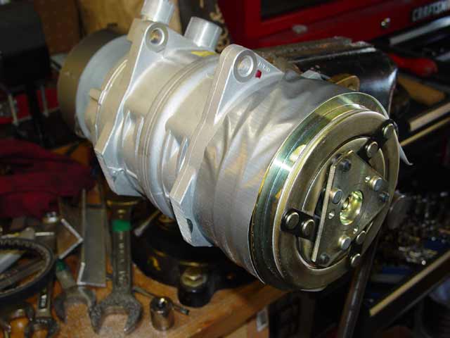
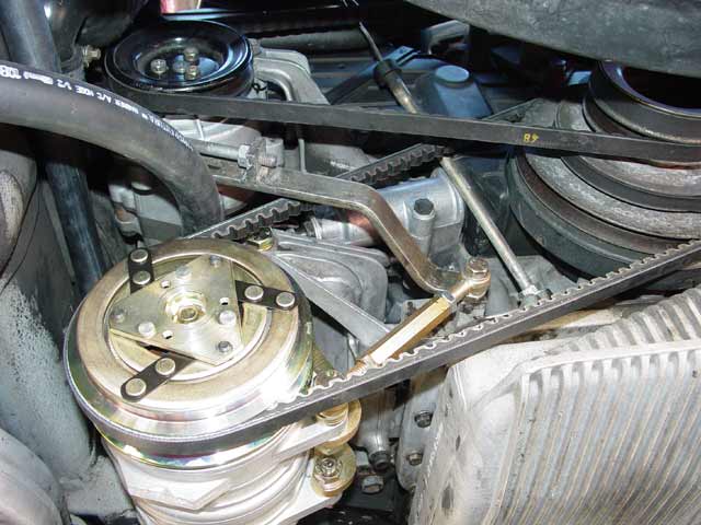
I didn't do a precise measurement, but it seems to me that the compressor sits about 1/2" higher than the old unit shown elsewhere on this page. I certainly don't mind the extra clearance. Ultimately I need to put a belly pan on. Regardless, it's better to have it tucked up a bit. One side issue... I had to put a belt on that was about 100mm longer, since I could not attach the fully shortened AC adjuster strut with the original belt in place. Oh well. Progress, eh? That adjuster strut is a very nice unit, BTW. It's a turnbuckle style, where you need only loosen the two lock nuts and turn the center barrel with a wrench to adjust. I wish the other adjusters on the car were as friendly.
Here is a better view of all the hardware, including the new smog pump adjusting strut. I don't know what possessed Porsche to set it up this way. The strut has to be removed to get the AC belt on and off. That's just wrong IMHO, but I made do with the parts I had and it works. It's probably not worth the effort to redesign it.
Sharp-eyed readers may note at this point that I haven't mentioned the expansion valve or the pressure line that I had rebuilt, and that the AC hose in the last two pics above is not routed correctly. That's because some bonehead rebuilt the line without preserving the orientation of the metal ends relative to one another. The front fitting that connects to the drier points up, not sideways.
 That's very annoying, because now it means that I will miss my Monday AC appointment and I will have to really bust my hump to get it done Monday night before dark and hope the AC shop can squeeze me in Tuesday. Oh well, at least it's easy to correct. I tie-wrapped the hoses up away from moving parts for now, since they will have to be moved to get the pressure line in. Also, I disconnected the AC clutch wire to make sure the compressor doesn't turn till I want it to.
Third Assault - July 26, 2004 66532 Miles:
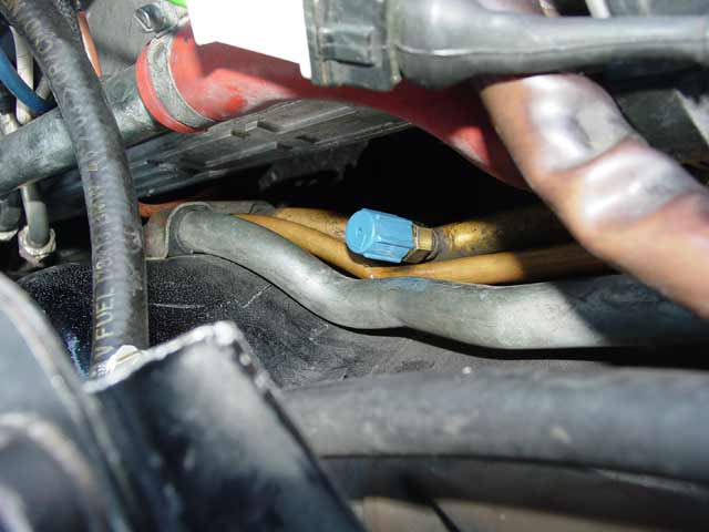
I talked to the AC guy today(Monday) and he told me that the hose could be twisted to the proper orientation, so long as I did it carefully and didn't turn it more than the absolute minimum necessary to line it up right... IOW turn it 90°, not 270°. So, I'm the bonehead... I tried to turn it by hand, but didn't want to force it. If I could have had the assurance of a pro that it was OK, I could have finished over the weekend instead of on a weeknight. Oh well. I did so carefully with two pairs of channellocks, and spent the better part of Monday evening from about 6:30 to 11:30 carefully threading the high pressure line back into place, installing the expansion valve, and generally buttoning everything up. I took a great deal of care with it; I might have been able to finish quicker, but my mind was on quality and so I took my time. Below is the new suction line from Griffiths, properly routed and torqued:
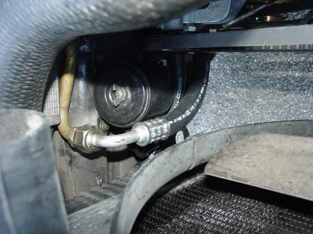
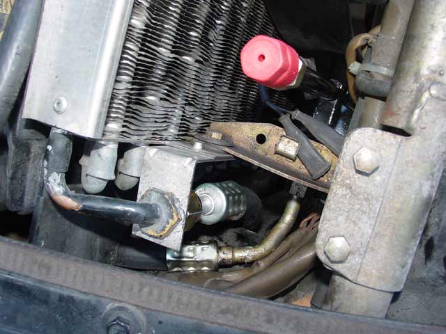
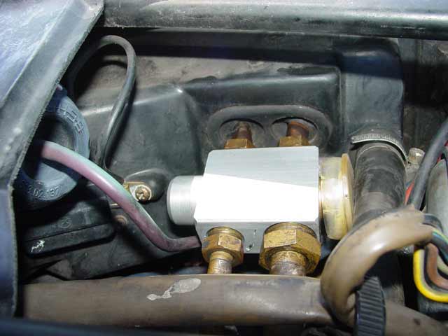
Below are the high pressure lines. The one at the very bottom of the pic is the one I had rebuilt, which connects the drier to the expansion valve. The next one up is the pressure line between the compressor and the condensor, also part of the Griffiths kit. This pic was taken taken after my trip to the AC shop... in fact these last 5 were. I connected up the old drier but had him install the drier that came with the Griffiths kit after flushing the system. It's shown here with the new drier in place and the R134a high side adapter connected to the drier. The temp switch is disconnected, because the system has been retrofitted with a pressure switch on the high side that turns on the cooling fan at 350psi and off at 290psi. The AC guy's reasoning is that the temp switch typically allows pressure to build up, frequently over 500psi before it engages the fan. The pressure switch should improve AC performance and protect against overpressure. My original plan was to connect the temp switch in parallel with the pressure switch and call it done, but... well, read on.
Here's a quick look at the low side R134a adapter. Just above it is the pressure line that I had rebuilt.... what a fun R&R!
Here is the new expansion valve installed. I put a touch of adhesive inside the plastic cap to keep it in place while I wrestled with things.
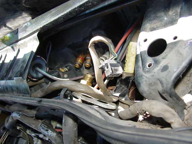
While I was fooling with this stuff, I noticed that the "green wire" was looking pretty sad, so I replaced it. Reitmeir should have replaced the damn thing, but screw it... I did.
The other connector near the ignition module looked fine so I left it: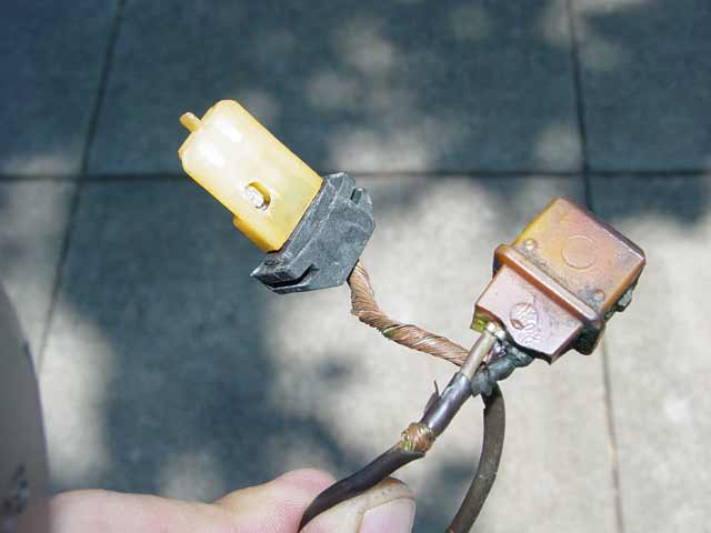
So, the result of all this is I now have AC that blows pretty cold, 42° when I'm under way at 40mph+ on an 85°F day. The AC guy complimented me on having put it all together with no leaks. He also checked for leaks in the evaporator and condensor using the same hot-element leak tester. On an 85°F day though, the center vent rose to about 53°F putzing around town. I am on the fence about trying a product called Ice 32 which I'm told may or may not make a difference. The AC guy said some cars are unaffected, some see a 10°F difference at the center vent. We'll see though...
It turns out I have a bigger problem. Twice now I've found myself stuck in traffic, and even without the AC on the engine temp continues to get hotter and hotter. On both occasions it became hot enough to turn on the electric fan, and once it made it to an estimated 220°F(estimate based on my experiments where I let the car get hot and observed actual temp with a thermocouple while watching the cluster gauge). It never boiled over, but it became hot enough to thin my oil and trigger the oil pressure warning a time or two. I compensated by holding a 1500RPM idle with my foot, which kept 2.5-3 bar on the OP gauge and slowed the climb of the temp gauge.
In both cases, once I got moving again... even 20MPH... the temperature came right back down. So the issue is airflow, and since traffic jams can't always be avoided I've decided to upgrade to twin electric fans in place of my mechanical fan. That will be my next Shark Attack. At this time, I plan to hook the new dual fans, each having double the CFM rating of my one electric fan, to the control circuit which presently runs my existing pusher fan, and mucking with the temp switch as well. I'm not sure what all is available for the radiator temp switch but I'm thinking 80-85°C. Also I will connect the AC temp switch in parallel. Then I plan to connect up the front pusher fan so that it always runs when the AC compressor is on. The plan may change over the next two weeks as I gather info, but that's what I have in mind at the moment.