On this page, I give details of how I set up my camera in the car, and some sample video. I chose the newly-released Aiptek GVS 1080p camera based on price and performance. It's quite a step up from my old Sony Hi8 camera, which would not work well in this application due to its weight and many moving parts. Also tape must run at normal speed to capture to a computer. An hour of video takes an hour to digitize. Going solid-state means that I can move an hour of video from the camera to the computer in a matter of minutes. It was $179 at Walgreens during the month of December, and while it claims(but does not deliver) 1080p video resolution, it offers 720p 60 fps(1280x720) with image stabilization -- perfectly adequate for my needs. With a 16GB card, I can capture over 5 hours of 720p video. The 1080p mode is 1440x1080 30fps. True 1080p is 1920x1080 60fps. I guess that in the mini DV-cam market, it's OK to claim you're selling a V8 when you're only delivering a V6.

Camera Mount:
After reading through the "Racing and Drivers Education" forum on Rennlist, looking at the different types of mounts being used and asking some questions, I decided to go with the Filmtools.com 3025 "Gripper" mount. I already had a Bogen branded version of the articulated arm supplied with the mount and knew that it was a sturdy unit. I had been considering the 4-1/2" "Cleat" mount but decided on the larger cup and better arm for stability.
I was hoping to be able to mount the camera right side up, since that would present the LCD screen to me in the rearview mirror backwards instead of backwards and upside-down, which would be the case with the camera inverted. I ended up adding my articulated arm to the end of the one that came with the Gripper in order to get the camera to sit right side up. Also I wanted the camera as high as possible so I could see as much of the road in front of the car as possible.
I mounted the camera to the arm with a tripod quick-release, since I would want to be able to detach the camera and use it at events while not driving the car. The quick release would minimize the fiddling required to transition between capturing driving footage and capturing other footage at events.

Below is a video showing the results of my testing with this setup. Unfortunately, there was far too much vibration, far beyond what the image stabilization in the camera could handle. Also the camera was so high up that the rearview mirror completely blocked the view of the road ahead.
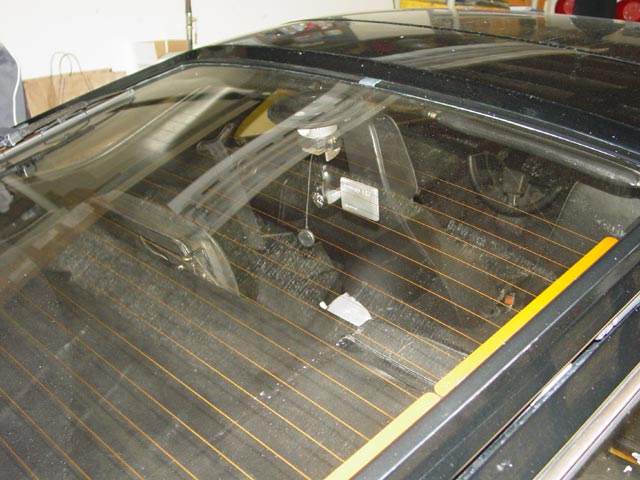
After a little head-scratching, I unscrewed the arm from the suction mount, finding a 3/8" stud as advertised. It turned out that my quick-release had 3/8" threads in the casting which I could use if I removed the bushing that allowed use on tripods with 1/4" threads. I mounted the quick-release to the cup and installed the camera to evaluate the camera position so that I could determine how close I was to a usable height. After looking at my initial test footage I decided that the most important factor to consider when mounting the camera was the vertical position of the lens, because that would determine whether or not I could see the road ahead on the captured video. You can see in the pic below that this is the largest cup that will sit on standard 928 hatch glass without running into issues with trying to seal on the defroster element. 1986 and later cars will have to contend with the third brake light, which is mounted where I have the suction cup.
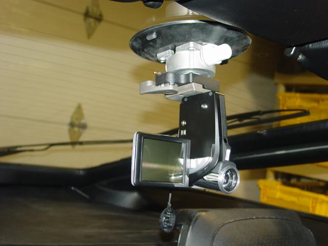
Here is a better look at the simplified mounting. I got lucky on this -- it turned out that the angle between the tripod mount on the camera and the optical axis of the camera exactly offset the angle of the hatch glass. With the camera mounted this way there was no need for further adjustment, as you can see in the later portions of the embedded video above. At least, there is no need for coarse adjustment.
Because of the relatively small base on the camera adjacent to the tripod mount and the cutouts in the rubber pad on the quick release shown below, the camera tilts slightly clockwise, as evidenced by the fact that the top of the windshield is lower on the right in the video. I am going to address this by milling the surface of the quick release block flat, eliminating the raised boss in the center, the raised ridge around the outside, and the e-clip in the center. I should then be able to glue a piece of hard fabric-reinforced neoprene from the hardware store to the quick release block, providing a firm and even mounting surface for the camera.

I will also trim the rubber so the LCD on the camera closes when mounted to the QR block. The LCD does not close far enough for the camera to detect it is closed and shut off. It's a bit inconvenient having to hold the power button(visible just under the LCD in the pic below) down for 2-3 seconds to turn the camera on or off. Once I modify the QR block so the cover can close while mounted, I will have effectively restored the auto-on and auto-off feature that is tied to the LCD position.

Update: Here is the quick release block after having it flycut. If you're friendly with a machinist, he may do this for next to nothing alongside other work, or while BSing and having a beer.

Next, I carefully eyeballed and measured out just enough cord-reinforced neoprene(from OSH or your local hadware store that sells diaphragm material) to support the base of the camera, and glued it down with 3M #80 neoprene adhesive.

Once it was dry, I cut a hole for the 1/4" mounting screw. I cut it a bit undersize so it would hold on to the screw and eliminate the need for an e-clip.

Here is the finished quick release block.

As you can see, when mounted to the camera there is plenty of clearance for the LCD to fold down.

Here it is with the LCD folded down. Just what the doctor ordered.


Further testing has shown that the camera sits at about 1/2 the angle it did before. It's an improvement and it allows me to use the camera as a handheld when I want, so I'll take it.
Camera Power:
One annoying thing about Aiptek cameras is that when you plug in any USB charger other than the AC charger that comes with the camera, the camera powers down and goes into charge mode. Many people have worked around this issue by buying extra batteries or cutting the USB end off of an AC charger and grafting it on to a DC charger(AKA "Frankencharger") but I was not willing to settle for that and kept looking for solutions. Thanks to the good work of mglobe on this Rennlist thread, I learned that people had been able to solve the problem by rewiring the USB connector. In particular Tom Davis posted the specific pinout info needed in post #193 of that thread, but unfortunately it turned out that the Aiptek needed +5v on the "X" pin which is not used normally, and Tom mentioned that none of the USB cables that he looked at had a wire connected to this pin.
The charger I used is made by Mizco, and is available at Microcenter as SKU #693200 for ~$10. It can be found in their online store. If you call or walk in, don't ask for Mizco, that's in the fine print on the back of the package. Ask for cellphone chargers and once there look for the package and SKU#. I wanted an adapter so that I could use any USB charger as opposed to making a custom charger, so that if I left on a trip without my charger or if mine became damaged I could easily get a replacement on the road and continue to enjoy the same functionality. I did some searching around and found that Molex made suitable connectors for making an adapter, female P/N 54819-0519 and male P/N 47014-0008. Of course the connectors don't just fall together into an adapter, but these would do. The next challenge was to find a supplier that didn't have a minimum order of 100 or 1,000 units.
 Mouser Electronics fit the bill. Here are their online store pages for the Male and Female connectors.
I posted to the above-mentioned thread to see if anyone was interested in having me source connectors for them. I wasn't too worried about saving a few pennies by buying a larger quantity, or about the fact that the shipping would cost about $6 whether I bought a single connector or a hundred. It was more about helping out.
It took about a week for the connectors to arrive; here is what they look like:

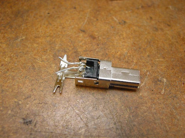
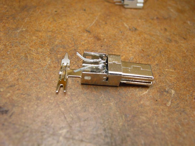
Since the USB spec calls for 5v to be present on the outer pins in the connector, I cut the middle 3 pins out of the female connector to get them out of the way and bent the outer two pins straight.

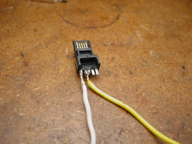
I then soldered some thin wire to the terminals for the male connector. It takes a great deal of care and a fine soldering tip, also you should use a thin(0.030") rosin core solder. In the pic below, I had accidentally bridged the "X" pin to the middle pin. I had to clean this up before proceeding. I ended up cutting off the three unused terminals. I don't know what it would do to the camera having these shorted, and I didn't want to find out.
When I lined up the pieces together I could see that the leads would be so short that there was no point leaving the insulation on.

I flattened out the male end cable strain relief since this was where the female connector would mount.

I then positioned the terminal block inside the connector shell...
...And pushed it in until it engaged the tabs on the side with a "click". There is a flat surface above the solder terminals where you can safely push with a small screwdriver.
Next I bent and trimmed the wires so that they lined up with the leads from the female connector. I didn't solder them yet, because I didn't want to put any strain on them. This was just a preparation step.

Next I butted the two connectors together in a vise, taking care to not squeeze them any tighter than necessary to hold them in position. The vise acted as a heat sink so I needed a larger, 25W iron for this step. The plastic is designed to withstand soldering temperatures of ~400�F but the iron is much hotter and can melt the plastic.

I soldered the cable strain relief to the top of the female connector. It's very important to only use enough solder to make the join, only on the side away from the spring fingers in the female connector. Too much and the solder will flow into the female connector, ruining it. Ask me how I know -- but I bought extra connectors knowing that I might have some failed experiments along the way. In fact, some of these pics are from my first attempt that ended up ruining the female connector, others are from my second attempt which was successful due to lessons learned. I recommend that anyone attempting this buy extra connectors, unless you are expert at soldering small assemblies.

The next step was to bend the tabs on the strain relief and on the female connector over.

At this point the assembly is rigid enough that you can solder the conductors. This was from my first attempt. Note the solder to the left of the cable strain relief. At this point it was OK, but later when I went to add reinforcement, the solder flowed into the connector through a gap at this point. I recommend that you not solder the strain relief just yet.

Before proceeding further, I tested the adapter with a car charger. On this model, the plug icon at the top right of the screen indicates success. On earlier models you will see a battery icon with a lightning bolt through it. Whatever the case, at this point it should behave the same way that it does when plugged into the AC adapter.

Since the two connectors butt together on the sides, there is little mechanical strength to resist twisting loose if force is applied perpendicular to the wide surface. To remedy this, I decided to solder some thin strips of steel to the sides of the assembly to tie the two connectors together. Even so, I recommend that people who take this approach come up with a strain relief setup so that the weight of the cable is not hanging from the adapter. I made the strips using a nibbling tool and some 16 gauge galvanized steel.

Here are what the strips look like. I will be sending these metal strips out with the connectors I sourced for other folks. You can also use steel wire, or any small strip of metal that can be soldered. I recommend against using copper wire, since it is soft and if it flexes, it will become brittle over time.

I laid the strip across the join between the two connectors. This is from my first attempt, which is why there is solder on the cable strain relief.

Solder the strip to the male connector first, because of the surface tension of the solder it will want to lift off when you lift the soldering iron. Hold the strip in place with a dental pick or similar when lifting the soldering iron. Stainless is preferred since solder will not stick to it. This is from my second attempt, as you can see there is no solder on the strain relief yet. The solder must flow smoothly to the metal; if it looks balled up on the surface you didn't get it hot enough. The joint pictured below was just hot enough, it could have used a touch more heat.

Next I soldered the other end of the strip to the female connector. Note that on the cable strain relief there is just enough solder to join it to the female connector, but no more. Any more solder on the strain relief or to the right of it and you risk ruining the female connector. Repeat for the other side. When finished, closely inspect the female connector for any solder that might have made its way into the housing. I had a tiny nub of solder protruding to the inside of the housing, which I easily removed with a dental pick. In retrospect I could have plugged these holes with solder mask, a latex compound that prevents getting solder where you don't want it, and then peels away or can be soaked off in water.

Next I snapped the metal cover in place. Normally it would be oriented with the tab facing the other way and engaged under the male connector shell, but there was no room to assemble it that way. I just wanted to cover the gap. Make sure that there is enough clearance on the side so that it does not short against one of the wires.

Next I covered the adapter with heat shrink tubing. I recommend using a highly visible color, since the adapter is tiny and easy to lose.

Here is the finished adapter installed on the camera.

To test it, I plugged everything in and set the camera to record while I went off to eat dinner and watch a DVD. This setup kept the camera recording happily for the 3-1/3 hours of my test. It provided enough power to prevent draining the battery as well. After my test I left the camera recording on battery power and it recorded happily for another hour and 45 minutes before shutting itself down.