964/993 Oil
Cooler Fan Operation & Troubleshooting
Stuff You’ll Find:
Component
Location/Part Number/Cost
Basic
System Operation
Troubleshooting
Techniques
Normal
Operating Temperatures
Component
Removal/Replacement
Systems
Known to be—or Previously—Operating Incorrectly
Known
Successful Repairs
More
Gory Details
NOTE: Whenever
“??” appears, it means that the information is unknown, in question, or was not
clear as provided.
Component
Location/Part Number/Cost:
Relay: Inside fuse box in (front) trunk. Relay is the same as that used for the A/C blower motor and the
rear heater blower. Part #811 951
253. Approximately $28 from a “discount” Porsche dealer.
Roy Eames reports the relay is “generic,” and can be purchased from
Pelican Parts for $15.80.
Oil
cooler and fan:
In right front (passenger side) fender, behind mud guard. Note that with a flashlight, you can see the
cooler/fan by looking through the horizontal grill at the right-front corner of
the car. You will have to lie on the
ground and look up to do this. A new
oil cooler fan (a.k.a. blower) costs approximately $100.
Oil
cooler temperature sensor (a.k.a. thermosender, thermoresistor or thermistor): Behind passenger-side mudguard—or behind the
passenger side headlight on a 993—on the top outer-most part of the oil cooler
unit. Part #964 624 110 00. Approximately $16.
2-speed
or ballast resistor: Behind the oil cooler,
mounted to the sheet metal. 0.45 Ohm
resistor. PITA to replace. Part #993 616 521 01. Approximately
$45.
Climate
control unit:
Mounted in dash. Part # varies by year
& model. Around $100 on Ebay
(depends on how lucky you get), around $250-$450 used parts
dealer, $900 new.
Basic
System Operation:
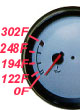
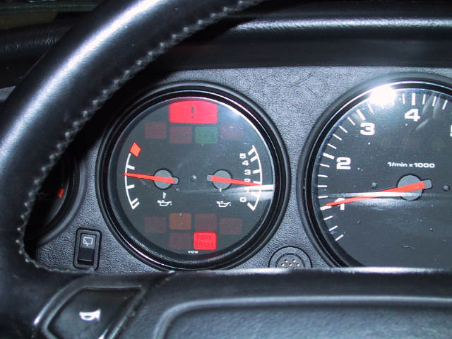
A reference
photo of the oil temperature gauge, with the white lines given a corresponding
temperature, can be found here (credit to Robin Sun and Viken):
At 87c/188F (per Bruce Anderson's
hi-performance book) for a 964, 83c/181F for a 993 (per manual), the oil
cooler thermostat opens and oil starts to flow to the cooler.
At 212F (964) or 230F (993), the thermosender—via the
control unit—starts the oil cooler fan in slow speed.
At 239F (964), the oil cooler fan switches to fast
speed. The 993’s fast-speed set-point
is unknown.
Troubleshooting
Techniques:
To
verify that the oil cooler thermostat is passing oil to the cooler, simply feel the
right-front fender (or wing) after the engine is warmed up. The fender should be noticeably warm to the
touch. You may also hear a
"gurgling" sound coming from the right-front fender, as oil flows
through the cooler.
To
verify your fan is operating with the engine at operating temperature (or warmer):
-Place
your hand under the horizontal grill at the right-front corner of the car and
feel for air.
-As
a reference, you can run your A/C, and check for airflow out of the horizontal
grill on the left-front corner of the car.
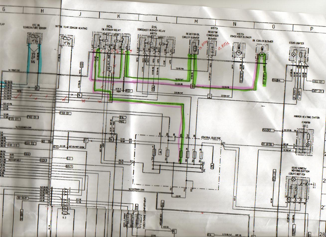
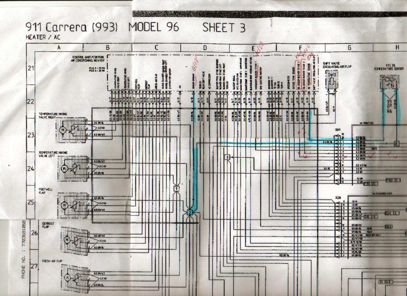
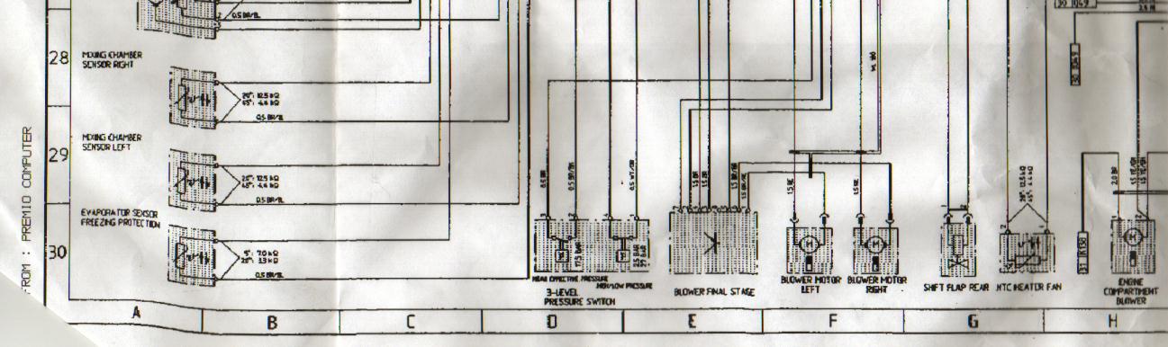
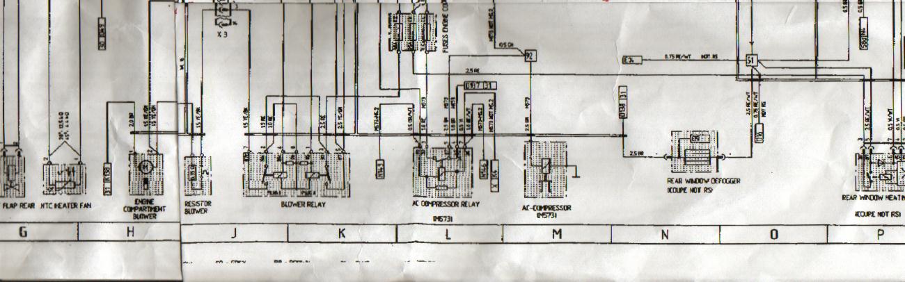
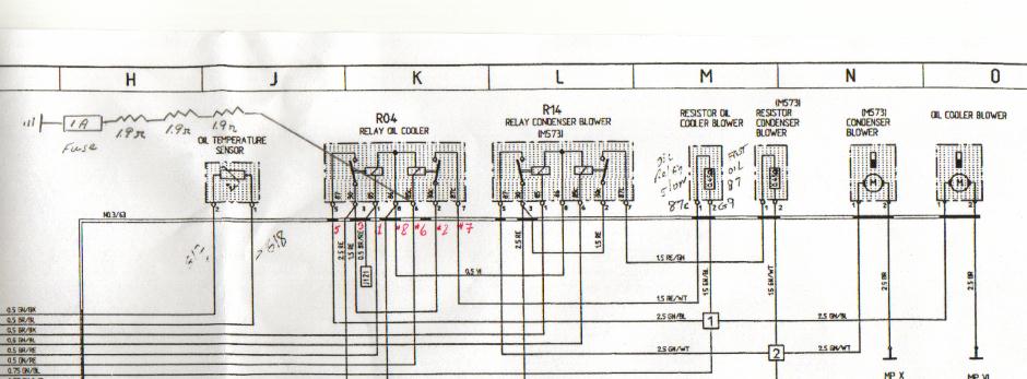
-Rough
(faxed and subsequently scanned) wiring schematics:
Before
going further, you’ll want to check the 30A oil cooler blower fuse in
the luggage compartment fuse box.
To
verify that the fan will physically operate in slow or fast speed:
Caution: Keep in mind the relay terminals are energized
(12V).
-Remove
relay R04 (oil cooler blower).
-Jump
terminals 3(30) and 7(87c) for slow speed.
Fan should run, even with the ignition off. If the fan runs in slow speed, your ballast resistor should be
okay.
-Jump
terminals 3(30) and 5(87) for fast speed.
Fan should run, even with the ignition off.
You
can check the A/C condenser fan similarly, removing relay R14.
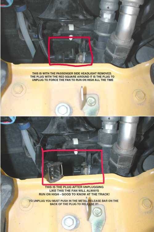
To
force the fan to run in fast speed when the ignition is on:
--On
a 993, remove the passenger side headlight, and unplug the cable shown here
(credit to E.J.):
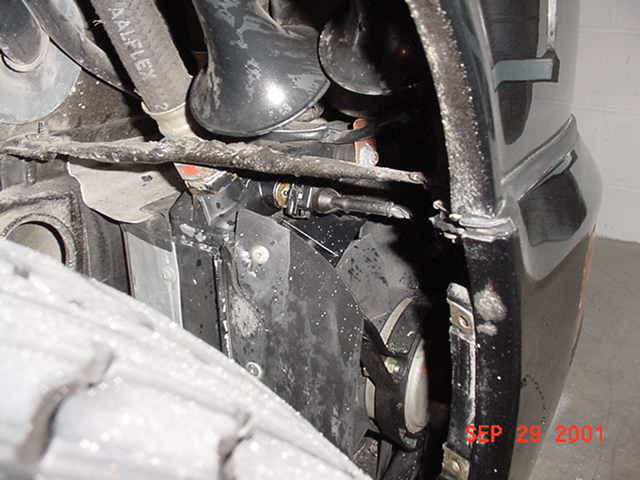
--On
a 964, the mudguard must be removed, and the cable above the fan unit
unplugged. The connector looks just as
it does for a 993. After unplugging the
cable, you'll probably need to secure the cable with a tie-wrap--lest it fall
into the fan's operating space (could be messy!).
A
photo of the 964 temperature sensor and oil cooler fan can be found here:
Oil Cooler Temp Sensor and Fan 2.JPG
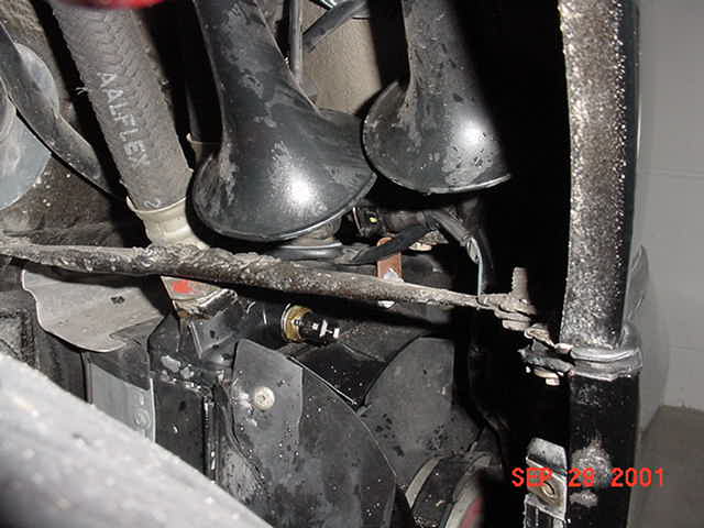
And
here is the temperature sensor unplugged, and the cable tie-wrapped:
Oil Temp Sensor Unplugged and Tiewrapped.JPG
-After
starting the engine, the fan may not start running in fast speed until the
engine has been running for a minute or so.
If
your A/C blower is operating, you can perform a "rough-check" of the
oil cooler fan relay by swapping the two identical relays.
If your A/C blower no longer operates, it's safe to say your relay is
bad.
Resistance
readings for the thermosender. With the
exception of the room temperature reading, all readings are taken across G12
& G18. G12 & G18 can be
accessed from the back of the climate control unit.
Climate
Control Unit Removal.htm
Or,
the equivalent readings can be obtained at 14-pin connector T-34 in the luggage
compartment, between pins #1 and #10.
T-34 is almost directly below one of the screws holding the long,
rectangular shaped plastic cover in place, between the fuse box and firewall,
on the passenger side. In particular,
the connector is visible with the rectangular cover in place, but you may not
have enough space to obtain resistance readings with the cover in place.
If
you take readings across connector T-34, you’ll want to take the readings from
the upper (female) part of the connector.
Readings taken across the male portion—with the CCU still connected—will
measure resistance of the CCU (not what you want).
Expected
readings:
-13.6-19.6
K Ohm when at room temperature, sensor removed from system (will vary widely
with room temp.).
-3.6-4.0
K Ohm at 60C (sensor installed, across G12 & G18).
-1.4-1.6 K Ohm at 85C (sensor installed, across G12 & G18).
-0.9-1.0
K Ohm at 100C (sensor installed, across G12 & G18).
Expected
behavior for a normally operating system:
-Oil
cooler thermostat opens at about the first mark past warm-up (at approximately
188F).
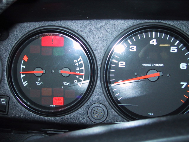
-At
» the 9:00
position (probably a little bit above the 9:00 position), the fan will start in
slow-speed, corresponding to » 212F (964) or 230F (993). This pic shows a typical start temperature:
Oil
Cooler Fan Starting Temp.JPG
-Very
little information on when the fan switches to fast speed, but the manual
specifies 239F (964 only, 993 unknown).
-This
pic shows a typical temperature at which the fan (having cooled the oil) shuts
itself off:
Normal
Operating Temperatures:
Varies
from car to car, but 122F - 194F when running on the freeway is normal. As is reaching the 9:00 position or a bit
higher when stuck in traffic on a warm day.
Reading at the 10:00 (248F??) position is not unusual when tracking a
car.
Owners
that have just restored automatic oil cooler fan operation have reported that
their engine does not runner hotter or much hotter than the 9:00 position, even
when stuck in stop-and-go traffic.
It
is safe to assume that routinely running at the 10:00 or 248F position is
abnormal, as is running above the 248F mark under any circumstances.
In
summary, “by the book,” an engine should probably run no hotter than the 194F
mark during freeway driving, and no higher than the slow-speed fan starting
temperature when stuck in traffic.
NOTE: R.G. & Sean S. have demonstrated
that—when stuck in traffic—their cars went from running halfway between the
9:00 and the 248F position with the fan OOS, to not getting any warmer than the
194F mark with the fan locked into fast-speed.
Component
Removal/Replacement:
-Relay: Self-explanatory, located inside
the luggage compartment fuse-box.
-Climate
Control Unit Removal.htm
-Oil Cooler Temperature Sensor Replacement.htm
-Oil Cooler Fan Resistor Replacement.htm
(for
a 993)
-AC
Condenser Resistor Replacement.htm
(with
photos)
And
some informative Rennlist threads, with respect to resistor replacement:
http://forums.rennlist.com/forums/ultimatebb.php?ubb=get_topic&f=3&t=003034
http://forums.rennlist.com/forums/ultimatebb.php?ubb=get_topic&f=3&t=001424
Systems
Known to be—or Previously—Operating Incorrectly:
-Roy
Eames had a problem with his fan's operation.
Basically, he thought his engine was running too warm at times (e.g.,
when stuck in traffic). It's likely his
fan wasn't running at all, and he was getting cooling purely from flow through
the oil cooler.
-E.J.'s
993 has a fan that will not operate automatically. He unplugs the oil temperature sensor (forcing fast-speed fan
operation) when running on the track.
His fan runs both in slow and fast-speed when jumpered.
-Patrick's
993 has a fan that will not operate in slow speed. The fan runs fine in fast speed, but not in slow-speed when
jumpered.
-R.G.'s
'91 C2 fan will not operate automatically in any speed. Both speeds operate when jumpered, and the
fan runs in fast speed when the oil cooler temperature sensor is unplugged. R.G.'s car runs no hotter than halfway
between the 9:00 position and the 248F mark (no fan operation). R.G. suspects his fan has been O.O.S. for a
long time, and is getting cooling purely from flow through the cooler. He knows he is getting flow through the
cooler, because he can hear a gurgling sound, and the right-front fender gets
very warm.
Another
R.G. observation. With the oil cooler
fan locked into fast speed, the engine’s temperature barely goes above the 194F
mark—runs much cooler than it did with no fan operation. Sequence of operation with the oil cooler
fan locked in fast speed:
a) Engine warms to 194F, thermostat
opens.
b) Engine temperature drops quickly to between the
122F and 194F mark and remains there—even in stop and go traffic.
-Sean S.’s 993 was running hot when first purchased, and the problem was corrected by replacing the thermostat. About 4 months later, he noticed his engine running hot again—averaging between the 9:00 and 10:00 positions. He found his oil cooler fan was not running at all.
Sean
also observed that with the oil cooler fan locked in fast-speed (oil
temperature sensor disconnected), engine temperature did not climb above 194F.
-Jai’s
‘95 993 had a slow-seed fan that would not operate. He has verified that the 2-speed resistor is faulty through the
relay jumper test.
Interestingly,
Jai’s A/C condenser fan 2-speed resistor was also faulty, and was replaced by
the dealer. The dealer verified the
resistor was faulty using the relay jumper test.
-Even more interesting, Larry N.’s ’95 had the exact same problem as Jai.
-MikeF’s ’94 had an oil cooler fan that would not operate automatically, and an A/C condenser fan that would cycle on and off in fast-speed. He verified his A/C condenser resistor as faulty by the relay jumper test and resistance readings. His oil cooler fan seemed to check out okay, but still would not operate automatically.
-Multiple cases of failed resistors—too many to name.
Known Successful Repairs:
-After
troubleshooting, E.J.’s problem is likely the $CCU$. This has not been verified by use of a donor CCU. In the interim, E.J. has installed a slow-speed
jumper (see below), which runs his fan continuously in slow-speed.
-Roy
Eames' fan works great now. He replaced
the temperature sensor and relay at the same time, so it's not
possible to tell which was at fault.
However, based on the resistance readings Roy took on his old
temperature sensor, he suspects the relay was at fault. Roy’s fan starts in slow-speed at » the 9:00 position.
-R.G.
traced his problem to a defective CCU.
The CCU being defective was verified by temporarily installing a
substitute CCU (which started the fan automatically). Considering the high-cost of a replacement CCU—and the advantages
of cooler oil temperatures—R.G. designed a jumper which runs the fan
continuously in slow-speed. This keeps
the oil temperature <194F:
Oil
Cooler Fan Jumper Diagram.jpg
After
running with the slow-speed jumper installed for a few months, R.G replaced his
$CCU$, restoring automatic operation of the oil cooler fan.
-Sean S. learned his relay was defective by swapping the A/C and oil cooler blower relays. After swapping, the oil cooler fan worked, the A/C condenser blower did not. Even though Sean has found the problem, he has elected to run with the temperature sensor disconnected (i.e., continuous fast-speed operation).
-After
replacing the resistor, Jai’s fan
now works automatically in slow-speed.
The fan starts at just below the 9:00 position, and his engine doesn’t
run any hotter than the 9:00 position—even when stuck in traffic.
-Larry
N. had both the A/C condenser and oil cooler fan resistors
replaced. His car now runs much cooler. He took resistance readings on the old
resistors, and found one reading about 700 ohms, the other around 7k ohms.
-MikeF.
replaced the A/C condenser fan resistor himself, finding it in horrible
shape—nearly 1/3 crumbled away.
Resistor replacement restored normal operation of the A/C condenser
fan—i.e., operating with the A/C with the ignition on.
Replacing
the temperature sensor restored automatic oil cooler fan operation. Mike’s fan now starts just above the 9:00
position.
Details
of Mike’s resistor replacement with photos are here:
AC
Condenser Resistor Replacement.htm
-Multiple
cases of restoring normal operation by replacing the resistor—too many
to list.
More
Gory Details:
-The
slow-speed fan jumper test already verifies the resistor is intact, but an
additional check is to measure resistance across the resistor:
· Measure resistance across
terminals #5 & #7 of the relay plug.
Values obtained to date are 0.8 ohms, 0.7 ohms and 0.6 ohms. This applies to both the oil cooler and A/C
condenser fans. Of course, an open
circuit indicates a failed resistor.
-Yet
another verification that the resistor is intact:
· Remove the relay, measure
voltage between terminals #2 & #5.
Should read around 12V.
· Jumper the fan in
slow-speed (across terminals #3 & #7).
· Measure voltage across
terminals #2 & #5 again. The
reading should have dropped to around 4.2V …. the voltage drop across the
resistor.
-More
continuity tests, to verify your wiring is 100% okay:
· From CCU G-12 to temp. sensor terminal #2 = continuity.
· From CCU G-18 to temp. sensor terminal #1, continuity.
· Temp sensor installed, between G-12 & G-18 = some
value depending on hot warm the temperature sensor is.
· Between K/22 & oil cooler relay terminal #1
(fast-speed control), continuity.
· Between K/10 & oil cooler relay terminal #6
(slow-speed control), continuity.
· Between G/9 (voltage feedback) and oil cooler relay
terminal #5, continuity (you may not have the voltage feedback on a 993).
· Between K/23 & A/C condenser terminal #6 (slow-speed
control), continuity.
· Between G-7 (voltage feedback) & A/C condenser
terminal #5, continuity (you may not have the voltage feedback on a 993).
-How
the relay appears to work:
· Terminal 1 = CCU control for oil cooler blower
fast-speed-at 12V when fan is off, »0.86V when
fan is on.
· Terminal 1 = 3-Level pressure switch control for A/C
condenser fast-speed-at 12V when fan is off, »0.86V when fan is on??
· Terminal 2 = Always "Hot" (12V) supply for
slow-speed fan. Shorted to terminal 3.
· Terminal 3 = Always "Hot" (12V) supply for
fast-speed fan.
· Terminal 4 = Not used.
· Terminal 5 = 12V, relayed power for fast-speed fan—not
powered when fan is off
· Terminal 6 = CCU control for slow-speed fan—at 12V when
fan is off, »0.86V when fan is on
· Terminal 7 = 12V, relayed power for slow-speed fan—not
powered when fan is off
· Terminal 8 = Only "Hot" with accessory
position, relay control power??
· There is a 75 ohm resistor
between 86 (terminal #8) and 85 (terminal #1) of the relay itself.
· There is also a 75 ohm
resistor between 86 and 85c (terminal #6)
To operate
slow-speed fan:
· CCU shorts terminal 6 through a diode??, which gives the
»0.86V.
(The 0.86V is verified. The
existence of a diode within the CCU is not.)
· Relay no longer sees 12V at terminal #6, closes contact
for slow-speed fan.
· Terminal #7 now powered through terminal #2 (12V), fan
starts in slow-speed.
To operate fast-speed fan:
· CCU (or 3-Level pressure switch for the A/C condenser
fan) shorts terminal #1 through a diode (which gives the »0.86V).
· Relay no longer sees 12V at terminal #1, closes contact
for fast-speed fan.
· Terminal #5 now powered through terminal #3 (12V), fan
starts in fast-speed.
The current through terminal #8—when the fan
is running—is approximately 12V/75 ohms = »
0.15A.