John Pirtle, October 7, 2002
http://members.rennlist.org/pirtle
Two excellent references are available for this job. David Chamberland's reference article is in the Journal on the 928 Owners Club site, and Fred Rourke's is in my email keepers. David Schmidt has posted some fabulous pictures of his '90 GT Flapectomy.
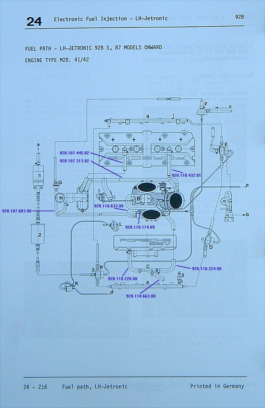
The official procedure is in the Porsche Workshop Manual on page 24-223 under the title "Removing and Installing Rotary Idle Actuator" (eleven steps for removal, and three for installation!). However, an absolutely invaluable diagram showing all vacuum connections and hoses is on page 24-216 (see below).
There are many reasons for this job -
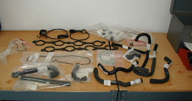
This is also a good opportunity to replace the fuel pressure
regulator and two dampers, and have the fuel injectors cleaned.
I did not remove the crossbrace as specified in the Workshop Manual. I also attempted to remove the manifold without removing the fuel rails, but the passenger side would not clear the crossbrace.
Torque values
from the Workshop Manual pages 10-07 and 24-224
|
Nm |
ftlb |
intake manifold nuts |
15 |
11 |
throttle-body housing bolts |
20 |
14 |
knock sensors |
20 |
15 |
fuel rail mounts |
15 |
11 |
intake manifold temp sensor |
40 |
30 |
NTC II temp sensor |
12 |
9 |
coolant temp sender |
25-30 |
18-22 |
|
|
|
M 8 |
20 |
15 |
M 10 |
40 |
30 |
Intake manifold diagram
from the Workshop Manual, page 24-216
(click for larger image)
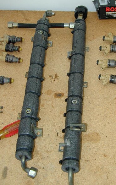
Before installing the fuel rails, I wrapped them in
some 1/2" (inner diameter) pipe insulation (Home Depot, $1.49).
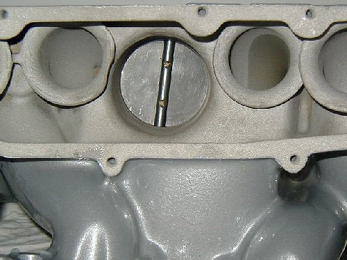
Tuning flap
If you have your intake powdercoated you will need to
remove the tuning flap (popularly called the "flappy").
During the powdercoating process the heat will melt the
plastic piece under the spring, and pretty much kill the
spring too.
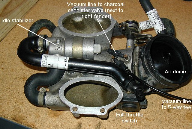
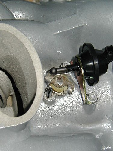
Pop the actuator's cup off the ball of the flap pivot, and
remove the two hex bolts that attach the actuator to the
intake manifold.
Remove the side covers from the "air distributor". The flap is
held in place with two screws. Remove them and carefully slide the
flap plate out of the pivot - note that the edges are cut at an angle
and may be sharp.
Next remove the E-clip and washer from the top of the pivot. Then
from underneath pull the pivot out. Be sure to block off the
holes to protect the upper and lower bearings (or remove and
replace them too).
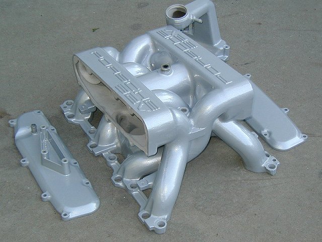
Powdercoating
A previous owner had painted the intake while it was
still installed. In some areas the original paint was flaking away.
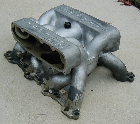
I took the manifold and the oil filler neck (mine is the alloy version)
to be sandblasted.
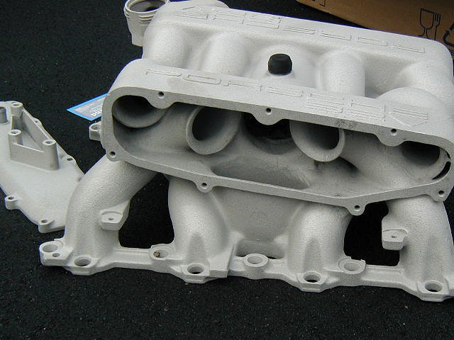
The powdercoater finished the pieces in bright silver and
then added a clearcoat. As a porous magnesium alloy it is important
that the pieces are first baked to outgas the metal. Otherwise
when the powdercoat and clearcoat are heated the
trapped gasses will be released and the finish will blister.

A future project is to do my valve covers - red!