- Function: Receives sensor inputs of engine operating condition, speed, and load. Using a combination of analog and digital processing of these inputs, the ECU sends voltage pulses of the appropriate duration and timing to the injectors. Also controls the operation of the fuel pump.
- Failure
Modes
- Dead: Nothing works. Usually due to major component failure.
- Mismatched: Wrong ECU for the engine and/or FI sensors. Causes various idle and drivability problems.
- Notes: The ECU is reliable and rarely faulty. Mismatched ECU's are more of an issue (more on this below, see the cylinder head temperature sensor and manifold pressure sensor entries) . Even mismatched, ECU's still often work OK, but may cause some drivability problems. Use the table above to verify that your ECU is correct for your engine type and number. The best test for an ECU is to swap it with a new or rebuilt unit. The Bosch D-Jetronic tester that can be rented from Pelican Parts tests some aspects of ECU operation, but it is not comprehensive.
- More: Frank Kerfoot, a former Bell Labs EE, did a fantastic job of reverse-engineering the schematics of the ECU. Using these schematics (and a lot of help from others) , I have developed a descriptive document that goes through each section of the ECU and describes the circuit operation. Here is the URL to the page:
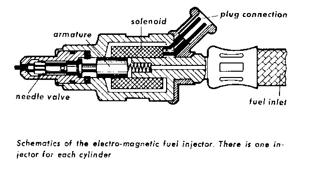
- Function: Receives pulse signal from the ECU, opening the injector, spraying fuel into the intake of each cylinder.
- Normal Value(s): The "Troubleshooting Guide" in the DSM states a nominal value of 2.4 ohms, measured at the ECU plug. It also recommends checking the FI ground connection point at the back of the engine if the measured resistance exceeds 3 ohms. I have measured values on my car between 2.79 and 2.53 ohms at the ECU plug and my car works fine - but I'll check that ground, anyway! Inductance values measured at the ECU plug on my car varied between 3.77 and 4.16 mH.
- Failure
Modes
- Clogged: Reduced output and poor spray characteristics, causing poor drivability and fuel economy. See URL below for test method.
- Open or shorted coil: No output, dead cylinder, causing poor overall performance. See URL below for test method.
- Stuck Open: Very rich mixture, possible hydro-lock of cylinder. See URL below for text method.
- Leaking (tip): Deposits cause the injector to leak into the intake. Results in rich mixture, poor fuel economy, drivability problems. See URL below for test method.
- Leaking (body): Dripping from the body of the injector. Causes fires that burn up your 914. Test method is to look and smell for leaking gas, or to look for huge flames shooting out of your engine compartment.
- Leaky O-rings: Loose or missing O-rings on the exterior of the valve can cause vacuum leaks. Causes lean mixture, lean surging, and drivability problems. See URL below for test method.
- Notes: The injection valves are reliable and durable. Today's reformulated gas can cause deposits, leading to clogged or leaky injectors. If you suspect a problem with your injectors, follow the procedures at the URL below to determine if they are functioning properly. Using an injector cleaner (e.g. Techron) every 10K miles is a good idea.
http://www.914fan.net/djet.html
also try: http://mail.symuli.com/vw/Djet.html
Flow rate data (courtesy of Roland Kunz):
Yellow (1.7L) - 265 cc/min @ 2.0 Bar, 3V, 0.15 mm ± 0.05 mm lift
Green (2.0L) - 380 cc/min @ 2.0 Bar, 3V, 0.15 mm ± 0.05 mm lift
- Function: Removes particulates from the fuel.
- Failure
Modes
- Clogged: Reduced output. Causes a number of drivability problems due to fuel starvation at part-load and full-load.
- Notes: Often overlooked during maintenance and while tracing FI problems. Replace the fuel filter every 10K miles. If you are still having supply problems, check the in-tank filter sock - did you know you have one?
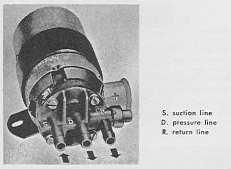
- Function: Supplies fuel to the injectors and cold start valve.
- Failure
Modes
- No pressure/inoperative: Can be due to electrical or mechanical failure. The engine will not run in this condition. See the URL below for a test procedure.
- Improper fuel line hookup: Very odd problems in maintaining pressure, with odd drivability problems. Check the factory workshop manual for the correct hookup.
- Clogged return line: I had this happen when I converted back from carburetors, my return line was clogged at the tank. High fuel pressure and rich, possible gas contamination of oil. If you can't regulate the pressure, this may be your problem.
- Failed Check Valve: The check valve keeps the pressure to the injectors and CSV up after the fuel pump is shut off to prevent vapor voids from forming and speed up starting. A failed check valve may cause some hot starting problems. There has been one report of a failed check valve causing the fuel pump to return all fuel to the tank, with no supply to the injectors. See the URL below for a test procedure.
- Notes: Detailed procedures on checking the fuel pump are documented in the Factory Workshop Manual. The electrical plug, contacts, and boot are often in poor condition due to exposure to heat, battery acid, and the environment. Contact failures are a common cause of a sudden shut-off of your car while driving. You should hear the fuel pump run for 1.5 seconds after turning the key to the "on" position. If you don't hear the pump run, check the fuel pump relay on the relay board, and the connection plug to the fuel pump. I keep a cheap Radio Shack multi-meter in my car just for this problem.
- More: There is an excellent reference on debugging fuel pump problems at the URL below:
http://www.914fan.net/fuelpump.html
I also have created a series of flow charts for diagnosing the fuel pump circuit and relays:
- Function: Provides additional air to the engine during warm-up to overcome drag due to internal friction of a cold engine.
- Normal Value(s): about 14 ohms of resistance from the connector to the body of the unit.
- Failure
Modes
- Stuck open: Fast idle. Check by removing input hose to the regulator after the car has been running for 10-15 minutes. If you feel suction on this line, the regulator is stuck open. See below for rebuild and rejuvenation procedures.
- Stuck closed: Poor running (low idle) after cold start. Check on cold engine by removing the input hose immediately after starting. If you do not feel suction, the regulator is stuck closed. See below for rebuild and rejuvenation procedures.
- Broken heater lead or heater coil: Engine stays at fast idle for a long time after starting (more than 10 minutes). Check by removing the regulator and grounding the case and applying +12V to the input lead. In a few minutes, if your heater is working, you should feel the base of the AAR getting warmer - eventually, it gets quite warm. If the lead is broken where it enters the AAR, you're out of luck. It is actually insulated through the crimped connector into the AAR - a really crappy design, as it's easy for the insulation to break down and short it, or for it simply to break off due to stress from handling. If it's broken right at the connector, you may be able to salvage it by rebuilding (see below)
- Shorted heater lead or heater coil: Check this if you blow the 25A (red) fuse on the relay board every time you try to start the car. See below for rebuild procedures.
- Notes: The regulator is open when cold, and closes over time as a heater inside the unit (+12V supply) acts on a bimetallic strip. The opening inside the AAR has a slot that starts off wide and gets narrow. The idle stays high while the wide part is open (~3-4 minutes), then drops off as the narrow part remains exposed (~10 minutes for fully closed). Even if the heater is non-functional, the engine heat will eventually close the regulator. Because the regulator is no longer available new or rebuilt, you will have to obtain a used unit or repair your own unit - you are on your own here!
- Does Yours Close Too Fast?: If you'd like for the AAR to stay open longer, try adding 2.5 ohms (four 10 ohm/10W power resistors in parallel) in series with the heater. This will reduce the heater power from ~14W down to ~10W, and cause the AAR to close more slowly. Should add a few minutes to the fast idle part of the cycle. Please exercise caution - that resistor pack can get hot, make sure it is safely secured.
- Rebuilding and Rejuvenation: These
things are NLA and working units don't show up for sale very often. I
recently sacrificed a frozen unit to figure out the best ways to revive
them and/or rebuild them.
- How does it work?: First, you have to understand how the AAR works inside. Click here to see a diagram of its guts. It's not so clear from the diagram, but the way this thing works is that in the top part of the unit, there's a cylinder with a slot cut in the side. The cylinder is open on the top, and rotates in the bore of the top part of the body. When the cylinder rotates, the slot moves past the opening in the side, so that air flows from the top port, through the open cylinder, through the slot, and out the side port. When the slot rotates away from the side port, air flow is shut off. The cylinder rotates because it's driven by a shaft on the bottom, that has a bimetallic strip connected to a slot cut in the bottom of the shaft. The other end of the bimetallic strip is secured by a screw to the body of the AAR. It's adjustable so that the AAR can be temperature calibrated. In the bottom of the AAR is a heating coil that warms the bimetallic strip when the car is running.
- Rejuvenation: This is your best bet, if your heater is still working and the lead is in good condition. AAR's are exposed to all kinds of muck in the airflow path, and are often stuck. The bimetallic strip can't provide very much torque to turn the shaft, so the cylinder has to move freely in the bore. Remove the AAR from the car. Turn it upside down and flush the side port with penetrating lubricant (e.g. WD-40). Flush, flush, flush, and flush some more. Plug the top port, fill it up with penetrating lubricant, and let it sit upside down for at least a day. Clean it out, flush it a few more times, then try again. If it still doesn't open and close, repeat the procedure until you tire of doing it and give up, and proceed to the rebuild procedure.
- Rebuilding: This is NOT a guaranteed
process, take this on only as a last resort. Your first challenge is to
get inside of the AAR. This is not an easy task. I have heard that you
can "pop" the top of the AAR off by jamming a large round screwdriver in
the side port, securing the base in a vice, and levering the top.
Personally, from my tries at doing this, I suspect that you will instead
break off the side port, and/or destroy the guts when it comes flying
open, or chop you hands to pieces. Your call, several people have told
me that they've done this and it works, I couldn't get it to work for
me. An alternative procedure
is to take a Dremel cut-off wheel (please use safety glasses, and
perhaps, a full face shield), and to very carefully go around the
perimeter of the flange on the body and cut it off, so that you're
removing just the top part of the flange (it should form a ring). Your
goal here is to leave a shoulder of the flange, so that you can epoxy
the top back on when you're done. Good luck.
Assuming you're successful and haven't been fatally injured by this process, remove the top. You should see the ceramic insulator with the heating coil in the bottom of the unit. If yours is in good shape, DON'T TOUCH IT. Put it aside. If your heater lead is broken or your heater is burned out, you have to remove the ceramic part completely. I don't believe you can do this without destroying it, because the ground pin and the heater lead pins are riveted through. Before proceeding, try to open the crimp that's holding the heater lead on the bottom of the AAR as much as possible, so the wire can slide through. You can get the ceramic heater out by inverting the unit, then using an awl or a punch to punch-out the center rivet. Rip it all out and toss it. You will be replacing the heater with three small 5 ohm, 5 Watt rated, wire wound resistors in series. Arrange all three in the bottom of the unit, and secure them to the base with epoxy or JB weld. One end goes to the ground pin in the base, the other goes to a wire that exits the AAR through the port in the bottom. Set aside. BTW, I HAVE NEVER DONE THIS - Dave Darling said he did it and it works.
Next step is to get the cylinder freed up. If yours is really stuck tight, you will probably have to remove the top port to be able to extract it. First, mark the angle of the top port to the top assembly of the AAR with a marker or a piece of tape. Clamp the top, stick a round screwdriver into the top port, and lever it off the top of the AAR. You can press it back on later with a vice and peen the edge to make sure it's secure. You should now be able to see the top of the cylinder in the bore when looking in where the top port was attached. Below, you'll see that the bimetallic coil is held on by a small screw. Carefully mark the exact position of the slot where the screw is attached - this is the temperature calibration position, you'll need to attach it later to this exact spot. Remove the screw, and pull off the bimetallic coil, the other end is engaged in a slot in the shaft that drives the cylinder. Soak everything in penetrating lube - the shaft, cylinder, etc. Next, you'll notice a small pin in the shaft, that limits the rotation of the shaft, and that must pass through a key slot in the body of the AAR if you want to remove the cylinder. Stick a flat end screwdriver in the slot in the end of the shaft, and GENTLY try to turn the shaft. Won't budge, right? OK, here's what I did. Invert the top and gently tap on the bottom of the shaft with a hammer a couple of times. Not too hard - you'll break off the pin. Now, turn the unit back over, find a small round end tool (I used the butt of a scredriver), and use it to tap the cylinder back down into the bore. Repeat this process until you can start to turn the shaft. Once you can get it to rotate, move it to the position where the pin is lined up with the slot, and then drive it through, and remove the cylinder. You'll find the bore is full of rust and muck. Keep cleaning, lubing, and testing the cylinder in the bore until it moves with almost no effort.
Reassemble, I would press on top port AFTER I put the cylinder back in, but BEFORE, I put the bimetallic coil back on. Make certain you DO NOT use the shaft of the cylinder for a pressure point, push from the body of the unit with a vice. Peen the top to hold it in place. Reattach the bimetallic coil to the exact position you marked when removing it. Use high-temperature epoxy to form a complete seal between the top and bottom of the unit, and wait 24 hours before testing to make sure the epoxy is fully set. Congrats, you should have a fully-functional AAR!
- Function: Senses cold-cold starting condition and provides additional fuel during starting to richen the mixture.
- Normal Value(s): Bosch says the cold start valve coil resistance should be 4.2 ohms. Measurements I've taken on a NOS 0 280 170 015 valve I have are R = 4.24 ohms. Coil inductance was 4.51 mH.
- Failure
Modes
- Open control wire from the thermo/thermo-time switch: Prevents valve from operating. Poor cold start operation. Check by inspection.
- Shorted control wire from thermo/thermo-time switch: Causes valve to stay open. Very rich mixture across all operating conditions. Check by inspection.
- Open or shorted thermo/thermo-time switch: Prevents valve from operating (open) or causes valve to stay open (shorted). Poor cold start operation (open) or rich mixture (shorted). Check by removing the switch, placing it in your freezer for a full 10 minutes (see notes section below), and checking for continuity from the terminal to the case. If there is no continuity, the switch is open and bad. Allow the switch to warm up to room temperature (70 deg. F) and check for continuity. If there is continuity, the switch is shorted and bad. Note that if you have a 75-76 2.0L, you have a thermo-time switch which has an internal heater that limits the time the switch is active. This switch also has two leads instead of the single lead on the thermo switch. I don't have a pin-out on the thermo-time switch and don't know which terminal is the switch and which terminal is the heater lead (+12V).
- Open or shorted thermo-time switch heater: The 75-76 2.0L thermo-time switch has a heater element which limits the time the switch is active. If this lead is open and the heater is inoperative, you could experience flooding or fouled plugs during repeated attempts to start the car. If the lead is shorted, you will likely blow a fuse (unknown which one) when you start the car, which may disable other systems. I don't have the pin-out for the thermo-time switch and don't know which terminal is the switch and which terminal is the heater lead (+12V).
- Open power lead from the relay plate to the valve: Prevents valve from operating. Poor cold start operation. Check by inspection.
- Valve Stuck Open: Very rich mixture across all operating conditions. See URL in the Injection Valve section above for a test method.
- Valve Stuck Closed: Poor cold start operation. See URL in the Injection Valve section above for a test method.
- Valve Leaking. Rich mixture across all operating conditions, fire hazard, poor fuel economy. See URL in the Injection Valve section above for a test method. Only safe solution is to replace the leaking valve.
- Mismatched thermo/thermo-time switch: Provides wrong temperature set point for operation, poor cold start performance. Check part number against the table above.
- Notes:
The cold start
valve provides a fine mist of fuel in the intake manifold to richen the
mixture during cold starts. For most of us living in the
continental US, the valve doesn't turn on except in the coldest
months of the year. The valve is controlled
by the thermo- or thermo-time switch and operates independently of the ECU. The valve
is active only when the key is in the "start" position and the
temperature is below the set point of the thermo-time switch. Actual
measurements of the switching temperature of a sample thermo switch
(311 906 161 C) indicate a lower temperature than quoted by the FWM, somewhere
closer to 0 deg. C / 32 deg. F.
Jeff Bowlsby found a reference (VWTG) that has a table of actuating temperatures for the early and later thermo switches, but not the thermo-time switch (note there is an error in the units conversion of the entry in the VWTG for first sensor listed below that has been corrected here):- 311 906 161 : -12 to -18 deg. C / 10 to 0 deg. F
- 311 906 161 A : 0 to -10 deg. C / 32 to 14 deg. F
- 311 906 161 B : -2 to -8 deg. C / 28 to 18 deg. F
- 311 906 161 C : -6 to -14 deg. C / 21 to 7 deg. F
- Function: Senses intake air temperature and sends signal to the ECU to provide mixture compensation.
- Normal Value(s): 300 ohms @ 68 deg. F, about 100 ohms @ 122 deg. F.
- Failure
Modes
- Open: Makes the mixture somewhat richer. Check with an ohmmeter.
- Shorted: Makes the mixture somewhat leaner. Check with an ohmmeter.
- Notes: The output of this sensor is used by the ECU to adjust the mixture for the intake air temperature. This is a secondary adjustment and has a small effect on the mixture. The sensor corrects for the decrease in air density with increasing temperature by leaning out the mixture. Disconnecting this sensor has the effect of richening the mixture, a common mechanic's trick.
- More: This sensor and the cylinder head temperature sensor are negative-temperature-coefficient (NTC) thermistors. Here's a URL on thermistors and how they work:
http://www.rtie.com/ntc/ntcappln.htm
Here's a URL that describes the manufacturing process:http://www.ussensor.com/manufacturing.html
Below is a URL to a reference that has two charts showing the resistance vs. temperature relationship for the intake air sensor and the engine temperature sensors used in D-Jetronic. The engine sensor data looks OK (about 2.5K at 68 deg. F), but could be from any sensor. Bosch used the same air temperature sensor on all D-Jetronic cars, regardless of model, so the data should be accurate for the 914's sensor:
http://www.icbm.org/erkson/ttt/engine/fuel_injection/d-jet.html
The charts are about half way down the page.
- Function: Senses engine temperature and sends signal to the ECU to provide mixture compensation. Proper part for your application and proper functioning is extremely important!
- Normal Value(s):
- 0 280 130 003 and 0 280 130 012: about 2.5 K ohms at 68 deg. F, less than 100 ohms with hot engine.
- 0 280 130 017: about 1.3 K ohms at 68 deg. F, less than 100 ohms with hot engine.
- See Notes section below for more data on the resistance vs. temperature values of these sensors.
- Failure
Modes
- Open: The ECU interprets an open sensor as a signal to greatly richen (e.g. I've measured an over 3X effect) the mixture. This usually makes the car impossible to start and causes it to stall if the sensor fails open while running. Check by disconnecting the sensor from the wiring harness and measuring the resistance to ground, refer to the values above.
- Shorted: The ECU interprets a shorted sensor as a signal to lean out the mixture (about 30% leaner). The car may run and start in this condition, but will have poor idle and drivability. Check by disconnecting the sensor from the wiring harness and checking the resistance to ground. Note that shorts are often intermittent, caused by nicks in the sensor wire and by exposed contacts to the wiring harness touching ground. Check by inspection.
- Stuck Value: I've heard of at least one case of the sensor being stuck at a value (e.g. 50 ohms) and not varying with temperature. Depending on the value it gets stuck at, it can result in either poor cold or hot performance, or both. Check by measuring with an ohmmeter as described above.
- Mismatched: The 1973 2.0L's came with the 0 280 130 017 head temperature sensor, 039 971 762 A ballast resistor, 0 280 100 037 manifold pressure sensor, and the 022 906 021 E version of the ECU. This set of components must be used together. Any substitution will result in idle and part-load performance problems, and possible poor fuel economy. Additionally, use of any of these 1973 2.0L components with a 1974 2.0L setup will also cause problems. See the table above for the suggested setup for both 1973 or 1974 2.0L engines. If you have a 1973 2.0L and you want to keep the original setup, make absolutely certain that you have the correct combination of components. The 0 280 130 017 head temperature sensor's cold (70 deg F.) resistance is about 1200 ohms, compared to 2300 ohms for the 0 280 130 003 and 0 280 130 012 sensors. Use of the ...017 sensor with the 039 906 021 ECU (1974 model) will result in a lean mixture during warm up, causing low idle and/or backfiring on over-run. Use of the ...012 or ...003 sensor with the 022 906 021 E ECU (1973 model), with or without the ballast resistor, will result in a rich warm-up mixture. Take the extra time and determine exactly which head temperature sensor is installed in your car and make sure it matches the setup.
- Notes: This resistance of this sensor is one of the primary factors in adjusting the mixture and it has a strong effect. An additional issue is the availability of the 0 280 130 012 sensor. I have found this sensor difficult to locate, and most shops substitute the 0 280 130 003 sensor for it. As far as I can tell, it is either exactly the same or nearly identical. Bosch even lists the ...003 sensor as being cross-referenced to the Porsche/VW part number 311 906 041 A. See the entry above for the intake air temperature sensor for theory on how these sensors work.
- Fixes for Crappy Warm-Up: For whatever reason, VW/Porsche made the CHT sensor such that the warm-up mixture is usually too lean, resulting in poor idle and drivability. Two ways to fix this. First, you can add up to 150 ohms of ballast resistance to the sensor to bias the curve up towards a richer condition. Don't go over this amount of ballast because it will begin to affect the warmed-up mixture. Second, you can construct a spacer as described on Richard Atwell's page, that delays heat transfer from the head to the sensor, making the mixture richer during warm-up. I made mine using materials from my local ACE Hardware: a M10x1.0 tap and wrench, 11/32" drill bit, M10x1.0 bolt, and a M8x1.25 coupling nut w/13 MM hex. Drill out the coupling nut and tap it to M10x1.0. Cut it down to 16 MM length. Cut a 16 MM stud from the bolt, thread it into the coupling nut so that when you attach the sensor on the other end, it just jams the stud in place. Align the flats and install. BTW, you can also do both fixes in combination (like on my car!).
- Installation Notes: Installing this sensor can be tricky. The best solution I've found is to buy a deep 13 mm socket and a 3" extension (I bought mine at Checker, about $5 for both). Use a Dremel tool with a cut-off wheel to cut off one of the corners of the four-sided end of the extension (the part that goes into the socket) to create a gap that the sensor wire can be threaded through. ALWAYS USE SAFETY GLASSES when doing this kind of work with a Dremel tool. Filing works, too, but it will take a very long time. Make sure to use the copper washer that comes with the sensor - the washer assures good thermal conductivity to the head and prevents loosening. Keeping the washer from falling off during installation can be difficult. First, to keep the sensor from being pushed back into the socket during installation (which will pop the washer off, and it'll fall into the head air fins), position the sensor so that it's sticking out a bit, then tape the wire with a single loop of masking tape to the extension. The wire will resist the sensor being pushed back into the socket. To keep the washer on the sensor, I use a couple of tiny drops of superglue to hold it in place. The glue bond will be broken when the sensor is tightened. DO NOT overtighten this sensor, just get it snug. It's easy to strip out the head threads and then you'll have to pull the engine to fix the problem.
-
More Data!!: Below is some characterization data I took on each
sensor at three different temperatures (one data point missing). Note
that these are representative readings - there is significant
manufacturing variation in these sensors. All data measured with a
freshly-calibrated Wavetek LCR55 meter.
Sensor Temp = 39 deg. F
(ice bath with thermometer)Temp = 61 deg. F
(room temperature)
Temp = 210 deg F
(boiling water at 1000 feet altitude)0 280 130 003 6.10 K ohms 2.94 K ohms 199.3 ohms 0 280 130 012 NA 2.85 K ohms 191.2 ohms 0 280 130 017 3.63 K ohms 1.74 K ohms 124.7 ohms
- Function: Biases the resistance of the head temperature sensor across the entire temperature range to cause the ECU to provide a overall richer mixture. Only used on 1973 2.0L's.
- Normal Value(s): 270 ohms
- Failure
Modes
- Open: Same effect as an open head temperature sensor (see above). Check with an ohmmeter.
- Shorted: Eliminates bias from head temperature sensor. Causes leaner mixture across full range of operation, resulting in drivability problems, possible backfiring. Check with an ohmmeter.
- Mismatched or wrong value: Many owners are aware that using a resistor to bias the head temperature sensor is a way of affecting the overall mixture of the D-Jetronic system. Depending on the value used and the setup, you can end up with a lean or rich mixture. Using a bias resistor other than as specified for the 1973 2.0L is only suggested when there is no alternative to obtaining good drivability.
- Notes: Used only on the 1973 2.0L engines in the combination of components described above in the cylinder head temperature section. It is used to bias the resistance of the 0 280 130 017 cylinder head temperature sensor. Since the ...017 sensor has a cold resistance value of about 1300 ohms, and a warm value of less than 100 ohms, use of the ballast resistor increases the value the ECU sees at both extremes by 270 ohms. If this resistor is missing from a 1973 setup, the mixture will be too lean across the whole temperature range. Use of this resistor in a 1974 setup will result in a rich mixture when the engine is warm. Make sure that if you have a 1973 setup as described above, that this resistor is present, and if you have a 1974 setup, that it isn't installed.
- Function: Limits intake manifold vacuum during overrun to reduce hydrocarbon emissions.
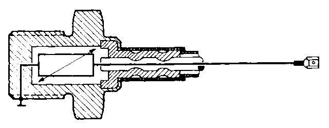
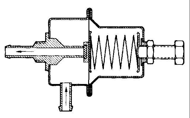
- How this thing works: The guts of the decel valve are shown below:

The valve limits the manifold pressure (pm) to the onset pressure (po) where the valve opens. When the pm drops to po, the pressure differential across the diaphragm is sufficient to overcome the resultant force between the tension and actuating springs, pushing the valve seat off of the end port, opening the valve, allowing air at atmospheric pressure (pa) to flow into the intake manifold, which limits pm to po. If pm tries to drop further (e.g. higher engine speed, greater pumping), the pressure differential increases, the valve opens further, more air flows into the manifold, which prevents pm from exceeding po.
NOTE: If you hook the valve up with the control port connected to the manifold, the side port connected to the manifold, and the end port connected to the air box, then the decel valve won't work Why? Because you're applying the same pressure to both chambers, which means there's no pressure differential across the diaphragm, so it never moves to open the valve. If instead, you connect the manifold vacuum to the end port and the air box to the side port, then when you reach the vacuum level where the force on the diaphragm due to the pressure differential is high enough to overcome the spring tension, then the valve will open. Note that a small area where the seat of the "end" port is against the diaphragm is also under vacuum, but it's much smaller than the area of diaphragm that's under vacuum on the control side, so its influence is small. Once the valve opens, it effectively limits the manifold vacuum to the set point level by opening more or less in response to the pumping volume changes due to engine speed.
- Failure Modes
- Leaky hoses: A leaky hose to the decel valve will either cause high idle or render the valve inoperative. Check all the hoses for integrity.
- Improper hose routing: For the valve to operate properly, manifold vacuum must be connected to the large "end" port and the air box connection to the "side" port. The skinny "end" or "control" connection is connected to manifold vacuum.
- Maladjustment: The decel valve is adjustable, and it's possible to have it misadjusted so that it is active during idle, causing a high idle. See below in the notes for how to adjust the valve.
- Leaky valve seat: Even new valves leak somewhat, but it is possible for the valve seat to become contaminated such that it leaks excessively. First, try cleaning the seat by pulling a vacuum on the control port to open the valve, then flushing the large "end" port with WD-40 to clean the seat. If that doesn't work, the valve must be replaced.
- Leaky vacuum chamber: If the diaphragm is cracked, the control part won't hold a vacuum and will leak. Pull a vacuum on the control port, if it bleeds off rapidly (1-2 seconds), the valve is defective and must be replaced.
- Notes: I do not have access to an unadjusted decel valve, so I do not know the factory setting. Based on measurements I have taken on my freshly-rebuilt 2.0L stock D-Jet motor, I suggest setting the valve to 17 inHg, as this is 2 inHg higher than the cold idle vacuum level, and will assure that the valve does not open under idle conditions. Adjustment is simple, pull a vacuum on the control port and try to blow through the valve. Note the point where the valve opens. Loosen the 13 mm locknut on the adjuster screw. To decrease the vacuum point where the valve opens, unscrew the adjuster, to increase it, tighten the adjuster. Tighten the locknut once the valve is set. If you want to set the valve more accurately, connect your vacuum source to the control port and to the end port, and slowly increase the vacuum, eventually, you'll hit the limiter setting and won't be able to pull more vacuum. Adjust as above.
- Function: Regulates the flow of blow-by gasses from the crankcase into the intake manifold. Part of the crankcase ventilation system, which includes the breather ports on the heads, which are connected to a fresh air supply from the air cleaner through a flame trap. This system reduces crankcase pressure (causing leaks), prevents oil contamination and sludging, and reduces HC emissions.
-
Failure Modes
- Missing: If the PCV valve has been removed and the opening is plugged, or some other way of venting has been employed (e.g. hose that simply runs under the car, canister, etc.), its likely that the amount of blow-by scavenging is less than optimal. Expect sludged oil, internal rusting, etc. Reconnect the system with new parts.
- Improperly Plumbed: Some systems have been improperly plumbed, with the hose from the PCV valve attached to the air cleaner instead of to the intake manifold (plenum). Only on very early 1.7L's (1970 - 1971) will you normally find this connection, and there is no true PCV valve (see notes below). In this case, there is no vacuum to draw air through the crankcase ventilation system, and only blow-by pressure drives the system. This results in poor scavenging, causing oil sludging and potential engine damage, and increases the risk of condensation and icing at low temperatures. Reconnect the PCV to manifold vacuum, and reset idle.
- Worn Out: Worn-out PCV valves leak too much at idle, causing high idle that cannot be set to spec with the bleed screw (too much air leaking). The rule-of-thumb for modern PCV valves is that if the PCV valve is in good condition, pinching the line shut while idling will cause the idle to drop about 50 to 100 rpm - on a 914, which uses a disc valve instead of a plunger, the idle drop may be more - I'm still researching it and will update this document soon with new info.
- Stuck Open: When stuck open, you have a very high idle and cannot lower it with the bleed screw. Try cleaning the valve in contact cleaner, if ineffective, replace it.
- Stuck/Clogged Shut or Plugged Off: Causes very poor crankcase ventilation, with likely sludging and corrosion. Blow-by pressure is relieved backwards through the system, up through the ports on the heads, causing oil vapor and liquid oil to be transported into the air cleaner box. Pinch the line shut while the car is idling. If there is no decrease in the idle, the PCV valve is clogged or stuck shut. Also, some previous owners or present owners get the idea that they can remove the valve and plug the opening - not a good idea. Causes very rapid degradation of the oil, with heavy sludging.. If the fresh air system for the head is connected, blocking of the PCV valve can cause this system to become the crankcase vent, causing oil contamination and spray, and possibly cause a fire hazard. Replace the valve, and install if missing.
- Notes: See my comprehensive page on the PCV valve for more details. The PCV valve is an essential component of the FI system, often overlooked. The basic principle of operation is that the valve permits minimal flow when at idle, and maximum flow at near full-load, when blow-by is highest. The PCV valve should be replaced every 15K, according to most experts. As mentioned above, the PCV valve is part of the overall crankcase ventilation system, which is driven by manifold vacuum. When engine conditions are so that the PCV valve is open, fresh air is drawn from the air cleaner through a hose connected to a flame trap, which splits off to two hoses, one for each cylinder head. Through a port on the cylinder head, fresh air is drawn through the pushrod tubes and into the crankcase, where it is mixed with blow-by combustion gasses. This mixture is then drawn through the open PCV valve and into the intake manifold, where it is drawn into the cylinders and burned. This system was implemented on 1.7 and 2.0L engines after 1972, and reduces crankcase condensation and icing at low temperatures.
- Function: Regulates fuel pressure (adjustable) to the proper pressure (spec: 2.0 bar, or 29 psig) for injection.
- Failure
Modes
- ??: I've never heard of a failure. These regulators are simple and reliable. If you are having a problem with getting sufficient fuel pressure or the pressure doesn't remain constant, it's likely the problem is with your fuel pump. If your pump seems to be working well, and the pressure is right, but you're getting a lean mixture, you either have clogged injectors or a clogged fuel filter. Follow the instructions in the Kjell Nelin article to test your injectors.
- Maladjustment: Fuel pressure is one of the three major parameters controlling how much fuel is injected (along with pulse width and injector flow rate). Low pressure will result in a lean mixture, high pressure a rich mixture, across all load conditions. One of the first steps in any analysis and adjustment of the D-Jet system is to measure and adjust the fuel pressure.
- Notes: The same regulator is used on all D-Jet 914's.
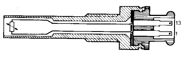
- Function: The manifold pressure sensor senses engine load by converting the intake manifold pressure level to an electrical signal that the ECU uses to set the basic injection pulse duration. A special part of the sensor operates at full-load, signaling the ECU to richen the mixture further.
- Normal Value(s):
- Primary Coil (terminals 7 and 15): 90 ohms. Using a Wavetek LCR55 meter on my MPS, I measured 99.9 ohms.
- Secondary Coil (terminals 8 and 10): 350 ohms. Using a Wavetek LCR55 meter on my MPS, I measured 365 ohms and 1.37 H inductance (@ 0 in. Hg) at the ECU plug (note - the measured inductance will vary by MPS, data taken on a newly-rebuilt 0 280 100 043).
- Use a hand vacuum pump with a gauge, pull 20 in. Hg. of vacuum on the port and monitor the vacuum level for 5 minutes. Should not drop below 15 in. Hg, if so, the unit has a vacuum leak and should be replaced soon.
- Failure
Modes
- Open or shorted primary or secondary coils: Results in no injection pulses, the car is inoperable.
- Vacuum leaks: Depending on the extent of the leak, the car can run slightly rich to very rich across the entire load range.
- Failed aneroid cell: Causes the car to run rich at idle, with poor part-load response.
- Maladjustment: Many owners and mechanics have tried to adjust the sensor by removing the epoxy-covered "plug" and turning the adjustment screw inside - this often results in unpredictable behavior, as adjustment of this sensor accurately requires a bench setup that only a few shops have.
- Notes: This is the most important sensor in the D-Jetronic system. As noted above, make absolutely certain that the sensor you have is properly matched to your FI setup. Mismatched sensors can cause drivability problems.
- More: I have developed a document that describes the manifold pressure sensor in detail.
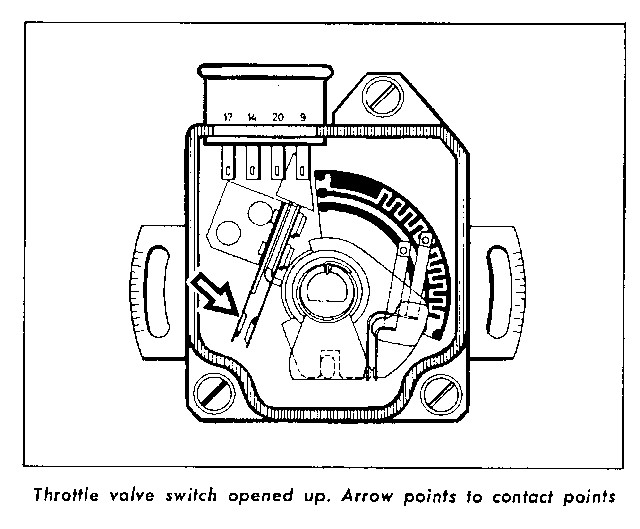
- Function: Senses throttle opening (not closing), sending pulse signals to the ECU to richen the mixture for acceleration. Also senses when the throttle is closed at idling, sending a signal to the ECU to provide idle mixture compensation. Also sends a signal at wide-open-throttle, but this signal is not used by the ECU for full-load enrichment, which is handled by the Manifold Pressure Sensor.
- Failure
Modes:
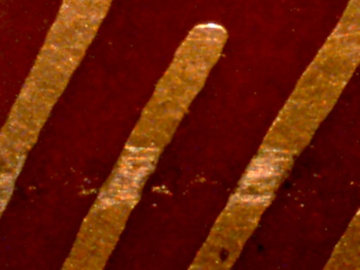
- Track Wear: Over time, the wiper track for the accelerator function will wear. Wear will be especially high at moderate to light throttle angles, corresponding to part-load cruising. Click here for a link to a 60X photo of accelerator track wear. While this TPS track is still good, the re-deposition of gold worn from the contact fingers by the wiper can be seen, and eventually will become sufficient to bridge the traces. This wear causes arcing and poor contact, resulting in the car "bucking" at a constant throttle angle. "Bucking" is a fairly common complaint and is almost always due to track wear. Check by disconnecting the harness plug to the throttle switch and driving at a constant throttle angle under part-load. If the bucking is gone, it's due to the switch. As I mentioned earlier, if you go to http://www.914world.com/ and search for user "davesprinkle", he's made a kit to replace the worn circuit board that restores your TPS to like-new condition.
- Maladjustment: The throttle switch needs to be precisely aligned to ensure that the idle switch is properly actuated, and that the full extent of acceleration is covered over the range of operation. Poor idle performance and transition to full-load are affected if the switch is maladjusted. The Pelican Parts web site has a very good article on how adjust the switch, using an ohmmeter.
- Notes:
The car will still run even if the throttle switch is removed! It
will accelerate slowly, and the idle may be poor, but it will
run. Proper adjustment of the throttle switch is critical. If
the idle switch does not actuate when the throttle is closed, the
idle circuit in the ECU will not be activated and poor idle
performance will result. Additionally, cars with ECU's that provide
over-run fuel shutoff will not shut off the fuel if the idle switch
isn't actuated when the throttle is closed while coasting. Proper
adjustment of the throttle is also important. If the throttle cable
and pedal stop are not properly adjusted so that the throttle is
completely open when the throttle is fully depressed, fewer
acceleration pulses will be provided to the ECU for acceleration
enrichment, and you'll be restricting your full-throttle input,
reducing horsepower.
I recently found out about two products that can be used on the contact tracks to extend their life. Deoxit D-5 cleans and leaves a lubricating film. It's available from CAIG Laboratories ( http://www.caig.com ). Another similar product is Stabilant 22 (VW part # ZVW 186001, Car Quest # SL-5). To use, you must open the throttle switch - be careful, there are some rubber positioning blocks that may fall out. Spray the contact track area and use a Q-tip to remove any excess.
- I don't have a 1.7L and have no idea of what this thing is or does. Sorry!
- Function: Sends timing pulses to the ECU to provide engine speed data and synchronize injection pulses.
- Failure
Modes:
- "Bouncing" or dirty contacts: A "bouncing" contact causes multiple injection pulses to be generated, resulting in a very rich mixture. Can only be checked by using an oscilloscope.
- Dirty (intermittent opens) contacts: Dirty contacts can result in missing injection pulses, leading to bucking and drivability problems. Can only be checked by using an oscilloscope.
- Open contact (not switching): Causes one bank of injectors to not fire. Easy to check with a noid light that plugs into your injector connector. Available from local auto parts stores (e.g. Checker).
- Worn cam rubbing blocks: When the blocks wear down very low, both switches turn "on" for most if not all of the rotation of the shaft. When both switches are on, this can lead to a no-start situation and very erratic operation.
- Misaligned switch: There is a fair amount of "slop" in the fitting of the switch to the distributor than can lead to problems. Make certain the switch is in the middle of the range of positioning in the distributor body.
- Notes: These contacts are very low current and are reliable, lasting in excess of 100K miles. Make sure if you install new contacts that you use a dab of Bosch distributor lube on the distributor contact lobes. Failed trigger contacts will prevent your car from starting and running. Later models of the contacts have a shield that keeps the lube from being sprayed onto the contact points.