(Requires no wire cutting.)
Most modern cars have an auto function on the driver’s side power window (this kit will also work on the passenger side window).
This is very convenient when entering parking garages and tollbooths or when closing the window exiting the car. I certainly missed this feature in my 944.
This kit will also work in your 911, 924, 928, 968 and VW type vehicles as the wiring is the same.
This kit will work in any positive switched vehicle (both motor wires at +12v when motor is at rest).
Kits can also be purchased for negative switched vehicles (both motor wires at 0v when motor is at rest), this kit is the same price.
I have worked for the last ten years as an electrical engineer, working with AC and DC motor control systems, logic and fuzzy logic control systems. I mostly work with elevator control systems and do a little automotive electrical engineering.
So I did some research and design for a system that could be installed by anyone without modifying the wiring (The spade connectors provided in the kit" fit directly) or hacking up the interior, as I like to keep things pure and original as far as the interior goes. Three months later I have a circuit that works in the manner listed below. This allows the window to function automatically, plus still gives the option of stopping the window anywhere in its travel. Two prototype units have been installed and tested in vehicles for over a year now without any problems.
Press switch in the up direction and release. The window will travel up until it is fully closed.
Press switch in down direction and release. The window will travel down until it is fully open.
When window is travelling up press the switch down momentarily. The window will stop where it is
When window is travelling down press the switch in the up direction momentarily. The window will stop where it is.
If the window is obstructed during its travel it will stop when stalled as if it had reached the end of its travel, this is a safety feature that operates if you get an arm or hand caught etc.
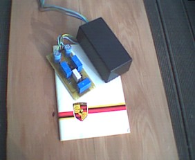
The circuit is built on a professionally etched fibreglass circuit board and is sealed in a plastic box.
Disconnect the battery (If your car is equipped with airbags you may wish to miss this step), not totally necessary, as the window motor wiring is dead as soon as the switch is disconnected.
The circuit is housed in a small plastic box that fits in the door between the bottom of the front window track and the outer door skin (directly behind the front speaker hole on early cars), it is a tight fit but will not rattle or cause any problems. It is secured in place with double-sided foam tape (No drilling required).
The unit has five wires; two inputs, two outputs and a ground.
The unit can be installed through the speaker hole in the early cars, but it is probably easier to remove the inner door panel.
Begin by removing the interior door panel. Make sure the window is closed. Remove the screws securing the door pocket, the armrest, speaker and interior door handle. There are also screws (capped) at the top front and top rear of the panel; these must be removed along with the locking button.
The panel is then only held on with plastic spring clips, carefully pry at these with a flat screwdriver. The panel must be slid upwards to disengage the armrest and the panel from the window track. It is also necessary to unplug the window switch and the mirror control switch. Carefully place the panel in a safe place.
Reach through the speaker hole and find the plug on the bottom of the window motor, remove this plug.
Plug the blue output wires from the module onto the spade connectors at the window motor, this is done by feel as you cannot see inside the door, do this first.
The spade connectors provided in the kit" fit directly.
Connect the two brown wires into the spade connectors in the plug that used to go to the motor.
The spade connectors provided in the kit" fit directly.
The ground wire (green / yellow) is fed up under the splash guard inside the door and through the alligator tube through into the door pillar, this may require using a draw wire of some sort to pull the wire through the holes This is easier if you first pull the rubber boot away from the door and fish the wire in two stages: a) first through the door, and b) then through the rubber boot into the interior of the car. In other words, remove the boot, insert the chase wire at the opening into the door and under the splash guard, pull the ground wire, remove the fish wire from the ground wire, insert the fish wire through the boot into the interior, then pull the ground wire through the boot and into the interior (this is much easier than it sounds). The green wire can either be grounded at the steel underside of the dashboard or a small hole can be drilled in the nearby steelwork. Make sure it is a clean tight ground point or the unit will not function correctly.
On later LHD models, there is a factory installed grounding strip just above the hood release handle. This consists of a row of hex headed, brass bolts all of which are holding brown wires in place. It can be seen by laying on the seat and peering up under the dash. This is an excellent place to ground the switch as all one has to do is remove one of the bolts, slide the end of the green wire into place (it is designed to fit the bolt), and re-secure. Just be careful, if you chose not to disconnect the battery, to not touch any of the other wiring.
The car door cannot be used as a ground path as the doors on these cars are not electrically grounded except through the hinges.
The plastic casing is then fitted between the door outer skin and the bottom of the front window rail. The module is held in place with double-sided heavy-duty foam tape. This is industrial tape, which sticks really, really well. In fact, once applied, it is nearly impossible to reposition. The door skin must be cleaned with a solvent first for this to stick well. Check carefully and "test fit" before removing the backing paper from the foam tape. This sticks really well and cannot be repositioned easily.
Next connect up the window switch (either remove it from the panel or bring the panel close enough to connect).
Test the unit, if the button works in the wrong direction swap the two brown wires from the unit where they connect to the existing loom and test again.
Cable tie up all the wiring so it is well clear of the window and any other moving parts within the door.
Refit the door panel.
No soldering or wire cutting is necessary.
A few screwdrivers (and a small drill if you need to drill a hole for the ground connection) are all that is required for installation.
Above is the circuit before being sealed in its plastic casing.
Note:
What is really neat is if a second unit is installed on the passenger side, it will automatically work from both the passenger side AND THE DRIVER'S side switches.
One unit will control one window.
Note:
If there is any problem with the unit, test your window by unplugging the unit and connecting the existing plug back to the motor, the switches fail on these cars quite often so this should be checked first. If the unit fails in any way send it back to me and I will repair or replace defective, not damaged, units for three years from the date of purchase as well as pick up return shipping costs. Owner is responsible for getting the unit to me in sound condition. Examples of "damaged" units include those with holes drilled in them, water logged units, and units with damaged or replaced wiring.
Installation (negative switched vehicle)
The installation is basically the same as above with regard to motor connections etc, if the wiring in your vehicle does not have spade connectors at the motor you may need to cut the wiring to install spade connectors (provided) so that the unit will fit directly and removal is possible without having to rejoin the existing wiring.
The output wires (blue) connect to the window motor or feed wires to the window motor.
The input wires (brown) connect to the wiring harness or feed wires from the switch.
There is no ground wire on this unit but instead a red wire that is to be connected to the 12v supply to the window circuit. This must be the same wire that feeds power to the motor(s), the same feed must be used in order to maintain the same protection on the wiring and motors that the designers intended at manufacture.
If the vehicle has relays to control the direction of the window motors then the red wire is to be connected to the wire supplying the relay contacts (not the coils as this is often fused separately).
If the vehicle simply has switches to control the window then the red wire should be connected to the +12v supply to the switch.
A male spade connector is fitted to the end of the red wire; a female spade connector is supplied to connect this wire to the +12v feed wire.
Heat-shrink tubing is also supplied to insulate connections, do not use electrical tape as this can dry out and fall off causing failure.
To Purchase a window express unit in North Amercia go to Paragon Products http://www.paragon-products.com/ and click on the window express picture. If you are outside the U.S area please contact me. The units are sold for $50 US + shipping. I accept Paypal https://www.paypal.com