
New and improved site with frames
this old one will be left up for reference, but no longer updated. Beware it contains incomplete information
News-
This website is beginning to get very disorganized, but such is to be expected on a project of this magnitude. I am taking on a new format, chronological order. Then when the project is completed I can sift through and separate into relevant categories. All updates will be posted at the top for a while.
A new chart a developed that may help:
Here is where I am stuck, I dont know which subtype of the 8051 processor to choose in IDAPRO. It makes a big difference on the disassembly of the code. Here is a screenshot of the options. If anyone knows which one to pick please let me know. Hitting cancel the program chooses c517 and does a good job disassembling.

Here are a couple screenshots of the flowcharts that can be made in ida pro. If anyone can help make sense of them feel free to chime in.
This is the beginning of the flow chart for the first of many functions


FRWILK's site is back up!!! Awesome news. frwilk's site
A forum has been created by DarkLightning for our use. Please sign up, we can use this forum to exchange ideas more easily. This forum is not intended as a replacement or even an alternative to Rennlist, we will only discuss things pertinent to this site there.
Disclaimer #1- No data on this website were paid for, and all info is free for everyone to use. If something on this website is yours, and you do not want it here, email me, mwn25@msn.com, and I will take it down.
Disclaimer #2- As with anytime that you work on your own car, you are taking a risk when making chips. Before editing any code, try to fully understand what you are doing. Double check your work, especially when it involves the ignition tables, or when you make your mixture leaner. Use a correctly calibrated wideband oxygen sensor (www.wbo2.com is mine) for tuning. Have a passenger ride with you, so you can watch the road while they watch the guage. You can destroy your engine by changing a few numbers in the eprom code, I KNOW OF PEOPLE WHO THIS HAS HAPPENED TO. And they were not even beginners. Be careful.
For an easy way of finding the basic fuel and ignition maps in the 951 eproms download the free program Motronic 911 available here. click
Screenshot 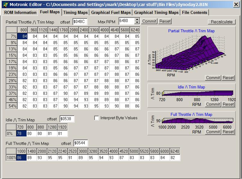
Just watch out for the glitch that changes the rev limiter to a random value whenever you save a new file. Also, you must save the Motronic 911 program to the same folder as your bin files, or the other way around, for it to work.
Update: Do not mess with ignition advance in this program, as the locations are correct but the values are not. This will be straightened out as soon as possible.
Here are the spec files for the early 24 pin chips, which do not come in the Motronic 911 program. Make sure you save them in the same folder with your bin files and Motronic 911 itself. I have not been able to make the second 2 work, but the first one finds the 1st and normal maps for the early turbo's.
first
second maps?
third maps?
If these are not working make sure they are saved as .spc files, for some reason they do not sometimes.
The software I use for straigh up hex editing (like fixing the rev limiter) is available here. click
Here is a nice tool for converting hex/decimal numbers and calculating the rev limit without mental math. Convenient program to have if you are lacking web access. Calculator also does the hex/decimal conversion. click
There are many hex compare tools out there which will highlight the differences between 2 bin files, but all the ones I have been able to fine are free trial for xx days, but then you must pay. This one is ok, but you have to convert from decimal to hex to find out where you are. click
Here is another hex/decimal converter for when the internet is available. click
Here is the chip burner that most people seem to be using. It is nice and cheap.
Does this burner work for
the early chips or just the late ones?
click
For eproms, you can use the same one over and over again if you like, they have long lives.
The only way to erase them is with a UV light. I use one called Datarase 2 that I purchased on ebay.
Make sure you erase chips for about 25 minutes, to insure their reliability.
Here is a source of the later 28 pin eproms if you wish to buy new ones. click
Looking for more!
24pin "early" stock DME
28pin "late" stock DME
early (all?) klr
The rev limiter is here. Formula is hex value translated into decimal times 40. A2 is the stock value.

Values in the code go from 0-255(decimal) or 0-FF(hex)
There are 3 sets of fuel ENRICHMENT maps in the 24 pin 951 dme ic.
There are 3 maps in each set, switchable with the altitude sensor wires, keep reading for details. Idle (engaged when the TPS/other sensors (which ones?) tell the DME that the car
is idling), part throttle, and full throttle (used when TP >60 degrees or rpm > 5000something).
The idle map is 1x5, meaning it is defined for 5 different engine speeds. The part throttle map is 12x12
meaning it has 12 possible engine speeds and 12 load points, forming 144 points total. The full throttle map is
1 x 15.
The rpm points in the part throttle are :
1(800) 2(960) 3 (1120) 4(1440) 5(1760) 6(2080) 7(2400) 8(3360) 9(4000) 10(4640) 11(5600) 12(6240) .
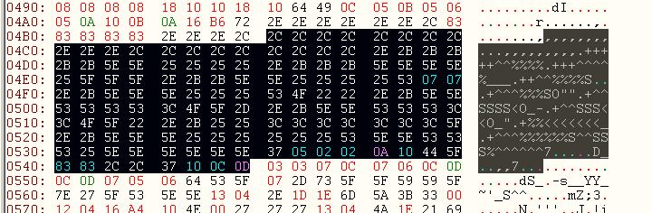
Note that the first 12 highlighted values are all for 800 rpm, the second 12 highlighted for 960 rpm, etc. Not the other way around, which would make the first 12 values for the first load percent etc.
For idle: 1(720), 2(800), 3(880), 4(1280), 5(1920)
For full throttle: 1(1000) 2(1480) 3(2000) 4(2120) 5(2240) 6(2520) 7(3000) 8(3280) 9(3520) 10(4000)
11(4520) 12(5000) 13(5520) 14(5800) 15(6240)
The load values referenced for the part throttle are unknown to me.
Here are their locations in the order of part, idle, full.


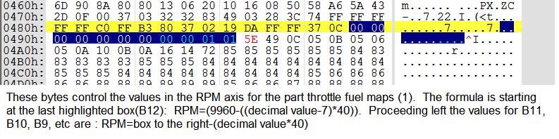
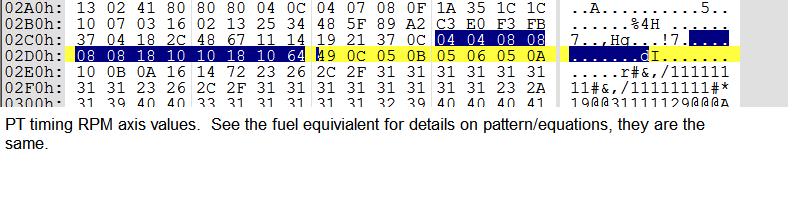
Changing axis values: Dont try this yet.....Im having confusion
The other 2 maps exist, but I will skip to the ignition maps now before I get around to posting them.
Ignition maps follow the same pattern, but there are 7 rpm possiblities in the idle map, as opposed to the 5 in the idle fuel map. As with the fuel maps, I am only going to post the first ones to save time for now.
Here are the locations, idle, full, then part throttle.


Changing Axis Values- Unconfirmed, I am still having trouble figuring this out so dont try it.
A common misconception is that the FQS switch located on the DME changes which maps on the eprom the dme is using. This is not true, the FQS only scales whichever maps are being used up or down, as to make up for bigger injectors or change every spark value for some reason.
The way to change the map being used is :
"To access the ROW map you need an adapter plug 944.612.421.00. It really is just a 1.8K Ohm resistor with the correct connector. I ordered mine from the dealer for about $18. Un plug the altitude compensator and plug in the adapter in its place. You then have to disconect the O2 sensor in the engine compartment and jumper between pins 1 and 3 on the DME harness. This grounds out the input from the O2 sensor and this in combination with the adapter plug tells the DME to use the ROW maps. Remember to disconect the battery before starting anything involving the electrical."
The fqs scaling based on position is shown at this site for stock chips, however these values are sometimes changed in aftermarket chips.
FQS scaling chip location 24 pin chip :
0x17B - 0x17E
128 is base fuel with 2.5 bar, stk injectors.
The first hex value scales fuel for position 0, stock, the hex value should be 80. (128 decimal)
The second hex values scales fuel in position 1, the hex value is 84, which converted to decimal is 3.1% more fuel than position 1. The third hex value scales fuel for position 2, and the fourth one scales fuel in position 3.
Locations of things in the late (28 pin DME CHIP) Hex code
First, a post from rennlist
|
As you may know there are three different
version of each map, which is used is depending
on code plugs outside the DME.
Version 1 Fuel idle 1538h Ignition idle 13ACh Fuel part throttle 148Ch Ignition part throttle 12CAh Fuel WOT 1544h Ignition WOT 1376h Version 2 Fuel idle 18A2h Ignition idle 17C8h Fuel part throttle 17F6h Ignition part throttle 16FAh Fuel WOT 18AEh Ignition WOT 17A6h Version 3 Fuel idle 1ABAh Ignition idle 19E0h Fuel part throttle 1A0Eh Ignition part throttle 1912h Fuel WOT 1AC6h Ignition WOT 19BEh Observe that these addresses is not the start of the data area, first comes information about the size of the map, then how the axes are scaled, then comes the data. The revlimiter is at 1171h.
Quote:
|
Second, the locations that I found using a buggy version of Motronic 911, use at your risk:
Part throttle fuel map, following same pattern as before, ignore the yellow
.
Idle fuel
Full throttle fuel
Part throttle spark
Idle spark (520, 1480, 3240, 6420 rpm- doesn't make sense take it for what its worth)
And full throttle spark
Overboost protection map is located at 0x16EE. The 12 values here /104 define the approximate boost limit in psi. Increase them until you do not have a problem, but leave them reasonable in case your wastegate line breaks.
schematic1
schematic2
schematic3
schematic4
Making an EEProm converter the Beab951 way
An eeprom is just like an eprom, but it can be electrically erased, which saves time and the need to buy a
UV eraser.
The EEPROM has two new pins that have to be dealt with. One is the WR~ pin 27, and the other is Address 12, pin2. The WR~ needs to be pulled high and A12 needs to be tied to power or ground.
The next thing is to strap power from pin 24 (2732) to pin 28 of the 2864(new eeprom). Pin 1 is not connected.
The layout does all these functions BUT the IC needs to be removed from the adapter board to program it.
The schematic shows a design that will allow you to plug in a ribbon cable with 24 pin socket on both ends (Digi-Key) and plug it into a adapter board with both the 24 and 28 sockets. I made one of these with wire wrap pins, if enough interest is generated, I can build some boards but the board companies don't work for free. I have also included spec sheets for both ICs.
Hope this helps,
Brian
Here is a schematic of the stock eprom. 2732
Here is a schematic of the 28 pin eeprom that can be used instead. 28c64b
And... eprom to eeprom "directions". First Second
I have not done this project yet, and if anyone attempts it and has anything to add or correct, please email me. Thanks Brian for this procedure and idea!
The Major Disassembly Begins
The processor in the DME is an 8051 derivative. Here is an 8051 faq with everything you ever wanted to know. click
A quick summary:
The 8051 is an 8 bit microcontroller, developed by Intel in 1980. It is the worlds most popular microcontroller, it is still produced and very cheap to buy. Its main disadvantage is that its architecture is "bizarre", meaning that some address spaces can not be accessed from some places. Its biggest advantage is that it is optimized for one bit operations, such as many of those needed in the Motronic ECU setting. I am glad to know that our processor is an 8051, because loads of information is available about them.
Our 8051 (does anyone know which derivative?):
It is known that the early 24 pin eprom cars use an 8051 with its internal ROM enabled, meaning some code is contained there instead of on the eprom. The later 28 pin DMEs have an 8051 with the internal ROM disabled, so all program code is contained in the eprom. Here is a link to FRWILK's website that describes how to convert an early dme to a late dme. frwilk
I have decided to make the later chips the first ones I focus on disassembling and analyzing, first because they contain more relevant/complete information, and second because contributors from rennlist have already started the process.
Here is a public domain 8051 disassembly program posted on rennlist along with the 28pin dme code disassembled in a text file. The instruction set can be found in the first link.
Any help analyzing what we have here is appretiated.
This is some information about the analysis process of some Motronic code from a BMW copied and pasted from this site. click It may or may not give us somewhere to start:
Here's how I disassembled Motronic
...
Using an 8051 disasm. pgm. (DIS8051 ver F.)
I got source code ...
Now which is data and which is code ?? hmm..
Well in the 8051, the way to move DATA out of CODE address space is the
movc a,@a+dptr instruction ...
The dptr is loaded by
mov dptr,#HHLL which assembles to hex 90 HH LL
Using a REAL kludgy code scanner I recorded ALL incidents of 90 and then
saved the next two bytes as addresses to the start of a MAP
Using the disassembler tag file, I tagged the region (approx.) from
0x4000 - 0x4fff as DB (MAPs) ...
With a little inside info, I found out that the EPROM is executed from
0x2000 up, the 0x0000-0x1fff region is ROM onboard the 80515
Adjusting the tag file and disasm'ing showed a bunch of "unresolved
address references in the region of "0x5000 - 0x6600" ...
After some thought, I had it figured out, ..
0x0000 - 0x1fff (Main internal code .. I need a friend at BOSCH!)
0x2000 - 0x3fff (Engine specific subroutines / interrupt service code)
0x4000 - 0x4fff (Data MAPs used by the EPROM subroutines)
0x5000 - 0x65ff (THIS IS THE GOOD STUFF!!!)
0x6600 - 0x7fff (More Engine specific subroutines working with 0x2000-3fff)
The MAIN MAPS in the region 0x5000 - 65ff are only refernced by ROM code
contained in the 80515 .. Now either a REAL cracking effort, or some
friends at BOSCH are needed to get the std 8k of ROM code and also the
code contained in the support chip (Yes, it seems Motronic has TWO ROMs
just to make life a little more difficult!)
Such is the current state of Motronic ... when I get back from vacation,
hopefully my SIEMENS 80535/515 databooks will be in and I can complete
my schematics of the Motronic circuitry ... then whith a little more work,
I'll have it all figured out ... (Yeah, right)
Oh, BTW, you might be surprized at how Motronic handles the spark timing
and dwell .. since it gets two signals, reference (1 pulse per 360deg) and
speed (N pulses per 360deg) .. It has a custom chip to run an angle counter
and comparator to fire coil ...
I'm going to simulate this using some std hardware: .. run the speed
signal thru a PLL (with div. by 3 in the feedback) setup to provide a
3x freq... count this in a counter, while comparing it to some latched
values (dwell and spark) in 8-bit identity comparators.. the comps output
to a flip-flop which thru an ignitor fires the coil ... a third comparator
will provide the reset signal to the counter ... all the CPU will need do
is look at inputs, go to a MAP or three and output two values to the
latched comparator registers .. the hardware does the timing for me :)
Oh well ... time to get ready for the vacation ...
Bitte,
Jim Conforti
(87 325is / 92 325i)
Finally, some relevant information I have compiled
from Rennlist over the years. Pretty much all of this is quoting or
paraphrasing TT, who has done this all already:
"The upper 4kB of ROM contains the constants and maps along with a jump table that allows manufacturers to change certain operations in the 24-pin DMEs even though the internal 4kB ROM in the micro is untouchable"
"Air temperature is involved in many of the DME's maps. Corrections are 0%-+12.5%."
"Altitude subtracts 6% fuel or does nothing"
"Load in Motronic = BPW (Base Pulse Width)/50 or 25 (unknown which) giving an answer in usecs to keep it an 8 bit number"
"Acceleration enrichment, start enrichment, etc, can increase BPW by a factor of 1.5 to 3 for short durations"
"The air temperature sensor is used for temp based ignition retard, warm start enrichment (9% more fuel @ 0 degrees F linear to 0% @ 60 degrees F), idel control valve duty cycle, and VAF volume to mass conversion (which is a feature removed when using a MAP kit conversion, meaning I can figure out where this is easily)"
"The tables editable in Motronic 911 are
enrichment tables that have nothing to do with BPW calculations."
"The processor tics ever 2 us"
"Lower limit for BPW in an 89 951 is .85 upper is 11 milliseconds."
"132 teeth on the flywheel, ref sensor detects a stud 21 degrees before TDC"
"There is an unused row in the chips for the VAF reading 5 volts, but the VAF is physically limited to reading about 4.6-4.8v"
"Motronic uses the same flag and counter cut fuel for overboost and for the rev limiter."
"For the 951, 1 atm map is approximately a load value of 110. The relationship between map and load is linear below 1 atm and non-linear while under boost" (because turbo heats up air so much?)
"I could remove all 3 enrichment maps, insert a constant multiplier, and the car would run 14.5 afr at all times" I will check this tonight
"Closed loop starts @ a minimum engine temp of 66 degrees F. Open loop = klr says WOT, RPM>5680, or boost >1bar absolute (load >110)"
"87 951 stock boost curve that the dme looks at to determine overboost
psi rpm
0 1500
10-11 3-5000
7-8 6240
pressure must stay over this limit for a certain time before overboost will be detected"
"5 bytes in the eprom define flywheel teeth and position of the reference sensor"
"One notch of change in the VAF spring correlates to 2% change in fuel mixture, so if you have 20% larger injectors you could tighten the spring by 10 notches" (not a good strategy, I am just putting it up for the 2% number)
"The BMW E30 M3 uses the same DME as the 951."
"The resolution of rpm in the 951 is 40 because 40*byte=rev"
"(decimal value*.682)-14=ignition degree" (not sure about specifics here)
"
|
" Obviously, you cannot have a trigger right at
TDC because you'll never be able to fire a spark
before TDC. So the reference-sensor trigger is
actually at 58.6-degrees BTDC"
Doesn't matter
where the ref mark is when the
teeth count is
available. Motronic uses the ref mark at 50-60
degree BTDC on cyl 1 because it also starts the
fuel injector batch fire at that time. Ignition
table values are stored in 1/4 tooth increments
and this affects calculated values when all the
different ignition map values are added. But
when converted to values used in the counting
process, the accuracy drops to the half tooth
value. Actually Motronic cheats. It only counts
whole teeth to
get to a specific spot on the flywheel, then if
the timing is at a half tooth mark, it polls for
the half tooth transition before firing the coil
otherwise it fires immediately for the whole
tooth. So on the 951, Motronic counts 66 whole
teeth transitions
(180 degrees) to get around to the coil
charge/discharge cycle for cylinders 2 & 3. If
you notice, the 911 uses 129
teeth because
there are 3 firing events per rev (43 teeth/120
degrees) and BMW uses 114
teeth which
allows them to use the same flywheel setup on
both 4 and 6 cylinder engines (57 teeth/180
degrees and 38 teeth/120 degrees). Yep. It's in chip S100 on the top board. That's the only chip I haven't been able to cross reference to a commercially available part. If you have the part number, I already have the rest of the circuit. If not, if you can extract the chip off a bad board you have, I have coworkers that could delaminate the thing to find out what it is. |
A RARE!! bosch technical documentation of their knock sensor, the one they say "might" have been used on the 951:
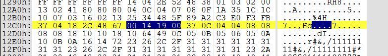
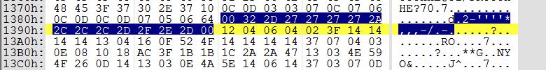
Here is the what the output of the knock sensor looks like on a spectrogram, I used my laptops sound card hooked directly up to the knock sensor to capture it using microsoft sound recorder.

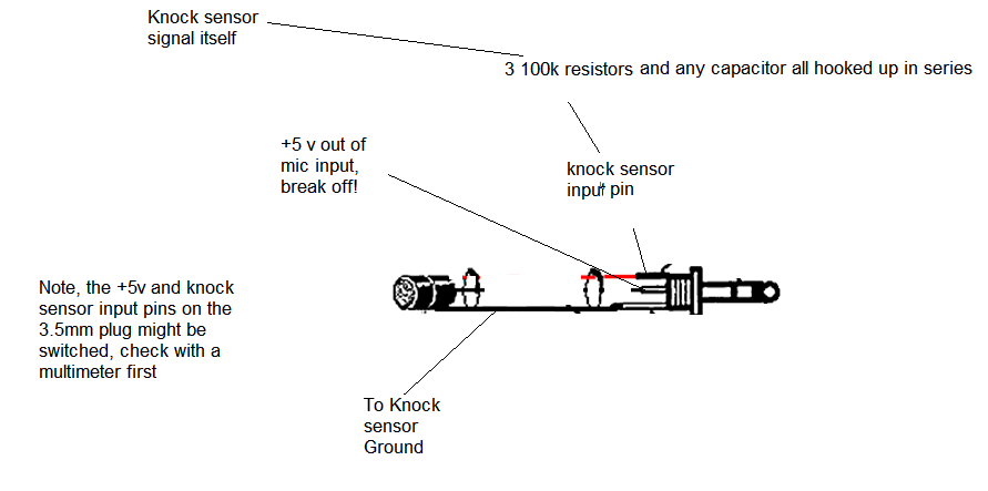
You can use this system I developed to listen to the output with a pair of headphones as you drive, as long as your soundcard has a mic input.
Here is the circuit I used.

And a sound file during some full throttle. If you can find some free spectrogram software it would be interesting to look at, my free trial ran out. Warning, watch your ears.
sound file
I am working on a light that will indicate a filtered knock using this circuit.

Here is a camshaft diagram for each cylinder, for reference.

<
|
|
|
|
| sponsor |