|
|
|
Above: Pelican Flintstone's Simplified Wiring
|
|
|
|
|
|
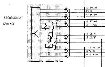
Above: A more detailed diagram. Note all of the connections to the controller/relay.
|
|
|
|
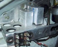
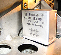
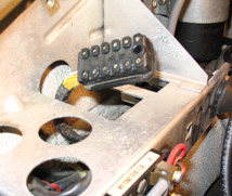
The fuse & relay panel in the engine compartment. Heater relay is the smaller box in the middle at left. Relay close-up - bottom left. Relay socket below. |
|
|
|
|
|
|
|
|
|
Above: A flow chart of the innards.
|
|
|
|
|
|
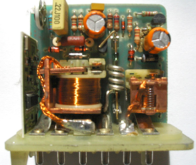
Above: Here is an inside view.
|
|
|
|
|
|
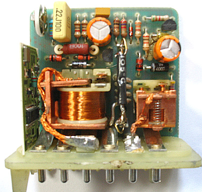
Above: Here is the modded relay - black wire is the jumper.
|
|
|
The Mod "You can open the Control module and jumper around the reed switch (silver coil in inside view above) or you can modify the module socket connections by removing the green/red wires from terminals 5 and 6. Then remove and relocate the black wire from terminal 4 to the 5 or 6 terminal. The first relay will now switch on the footwell blowers and will be controlled by all the sensors in the system. Be sure to tape the unused wires. The down side to changing the socket wiring is that the next owner will be totally confused by the mod if they reinstall the rear blower. Secondly, the engine overtemp sensor might want to turn the footwell blowers since the system still thinks the rear blower is still there. You would need to defeat that function too, although it appears that the stock system operated in the same half assed way. I guess the factory figured that in the summer the footwell blowers would be switched to the off position, if and when the rear blower came on". "The control module has 12 connections. From what I gather the module appears on Carrera cars with manual heat and AutoHeat. The AutoHeat systems have the additional circuits in the console between the seats for the interior and exterior duct sensors. The control module alone has the oddball speedometer sensor on terminal 1, Terminals 9 & 11 to the starter that defeat the system during cranking and terminal 10 that goes to the blower temperature switch, which I have been told uses the rear blower to flow air thru the heat exchangers when the engine gets too hot. The other connections bring power in or out to control the blowers." "What is happening with the mod is you are removing the reed switch ( the permissive element ie: rear blower works, then footwells work) from the circuit. The rear blower is fused from fuse 1 on the rear panel and the footwells from fuse 2. The OEM wiring has the rear blower and the footwell relay solenoid on the same circuit and this doesn't change with the use of the jumper." - all from Pelican mysterytrain on Pelican thread here |
|