1988 911 Nippondenso A/C Compressor Rebuild
OK, earlier 911 air conditioning won’t ever remind you of being above the Arctic
Circle. And because
of its design, the system has a lot of places in which leaks can develop. One of the more
common points
for a refrigerant leak is at the shaft seal of the compressor. You may notice some oil on
the compressor
mount or on the underside of the decklid in a line from left to right above the
compressor. Many folks
decide to buy a new compressor to solve this problem. But if you’ve priced new or
rebuilt A/C
compressors you know that they can be quite expensive. However, with about $25 in parts, a
three
out of 10 skill level and 3 beers worth of time you can reseal your own compressor.
Tools you will need:
Supplies and parts you will need:
The compressor that I rebuilt is a Nippondenso model 10P15C and
the system is still using Freon
(R-12). Make sure that you have the same compressor by looking at the model number
on the
small plate on the back of the compressor.
I ordered both a shaft seal kit and a gasket set so that I would end up with a totally
rebuilt
compressor. You can, though, choose to replace only the shaft seal. The shaft seal kit
has:
1) a new spring-loaded, carbon shaft seal, 2) a metal seal retaining ring/seat, 3) the
o-ring for the
seal seat/retainer, 4) a new circlip to hold the assembly in, and 5) new washers for the
head bolts
(these are the long bolts that hold the compressor sections together).
The compressor gasket set contains mostly o-rings: 1) three large o-rings for resealing
the case
sections, 2) four small o-rings for resealing the suction and discharge fittings - where
the schraeder
(sp?) valves are located (you know, like the valves on a bicycle tire/inner tube), 3) one
small o-ring
for the shaft seal seat (a duplicate for the one in the shaft seal kit), and 4) five
washers to use with
the head bolts (again, duplicates for the ones in the shaft seal kit).
Before beginning you should have any Freon that’s left removed from the system by an
A/C shop -
it shouldn’t cost much and with Freon at $50+ per lb. they should give you some sort
of credit for
when you have it refilled. Discharging Freon (R-12) into the atmosphere contributes to the
destruction
of the earth’s ozone layer and is prohibited by U.S. EPA regulations.
Now you are ready for the rebuild. Begin by removing the compressor from the car and the
clutch
assembly from the compressor.
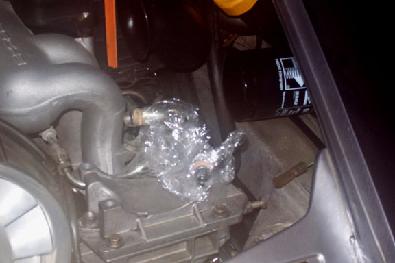
1. Undo the two hoses from the compressor - the smaller fitting uses a 7/8" or 22mm
wrench and the
larger fitting uses a 1 and 1/8" or 27mm
wrench but I carefully used a big pair of channel lock pliers
since I didn’t have an open-ended wrench that large. Secure
plastic wrap with rubber bands
around the hose fitting ends to prevent system contamination.
Don’t lose the o-rings on the hose fittings.
Picture 1 Compressor removed, hoses wrapped
2. Remove the three bolts that hold the compressor to its mounting plate, using a
1/2" socket. Now you
can tilt the compressor forward and take off the belt. Also disconnect
the clutch wire.
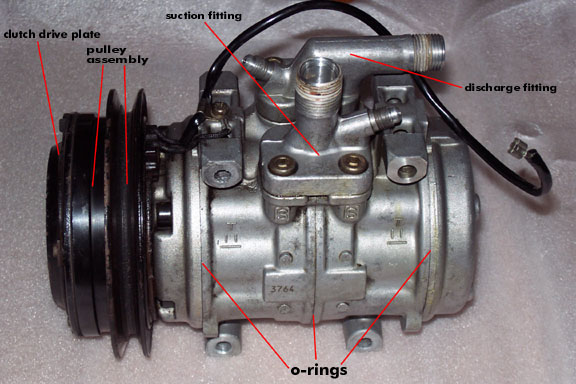
Picture 2 Compressor overview
3. At the bench, kitchen table, or wherever (but probably not at the local tavern), remove
the 12mm nut
that is exposed at the nose of the compressor/clutch assembly. You need
to hold the clutch drive plate
in place to get the nut off or the assembly will just spin. This is the
outermost piece of the clutch that has
the rivets showing. It’s only about 3/8" or ½ " thick and is separate from the pulley. Again, I carefully
used a large pair of channel locks but the proper tool is a strap
wrench. Once the nut and lock washer
are off, the plate just pulls off. You can help it by carefully prying
between the plate and the pulley
assembly behind it. Watch for the spacers between the drive plate and
the pulley and set them aside for
reuse.
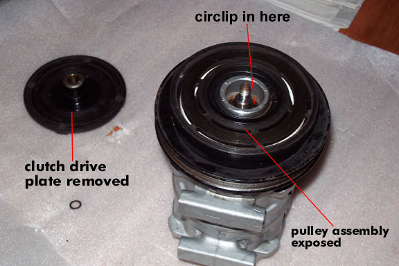
Picture 3 Clutch drive plate removed
4. The pulley is held in place with a 37 mm circlip. It doesn’t come with the kit
so try to remove it carefully
enough that you can reuse it unless you have a good local source for
such things. I don’t. The pulley may
be somewhat difficult to take off but you should not need anything like
a gear puller. If you look inside
the pulley’s shaft tube you can see the bearing that carries the
pulley held in by a retaining spring. This
may need to be replaced at some point. Mine did not require
replacement.
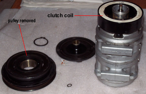
Picture 4 Clutch pulley removed, exposing coil
5. The ground for the clutch and a clip for the clutch wire are attached to the
compressor by a phillips head
screw. Remove it now. I had to slot the screw head with a Dremel tool
and use a large flat-bladed
screw driver because the screw was too tight.
6. The magnetic coil is held on with a 46mm or so circlip. Remove it and, again, set it
aside for reuse if
possible. Pull the coil off. Notice that there is a locating pin on the
compressor that mates with a hole
in the coil for reinstallation. My coil had three holes but only one is
in the right place.
7. Take the woodruff key from the compressor shaft and set it aside so that you don’t
lose it.
Now for the actual compressor stuff. The compressor consists of four sections: two end
caps and two
thicker middle sections with the pistons, cylinders and wobble plate (on the compressor
shaft).
1. Remove the five compressor head bolts using a 6mm hex socket or key. Each has a washer
and you
can discard them since you have new ones from either kit.
2. If you are going to reseal the compressor take off the suction and discharge fittings,
noting their
placement. They will go on the wrong way (ask me how I know) and if you
do happen to get them
on wrong during reassembly just remove and switch them. Don’t
remove these if you are not going to
reseal the case.
3. Once the head bolts and the suction and discharge fittings are removed the case
sections will just split
apart under hand pressure. To replace the shaft seal only, pull off
just the front section of the compressor.
You will be able to see the tops of the compressor pistons and one of
the large o-rings for the case.
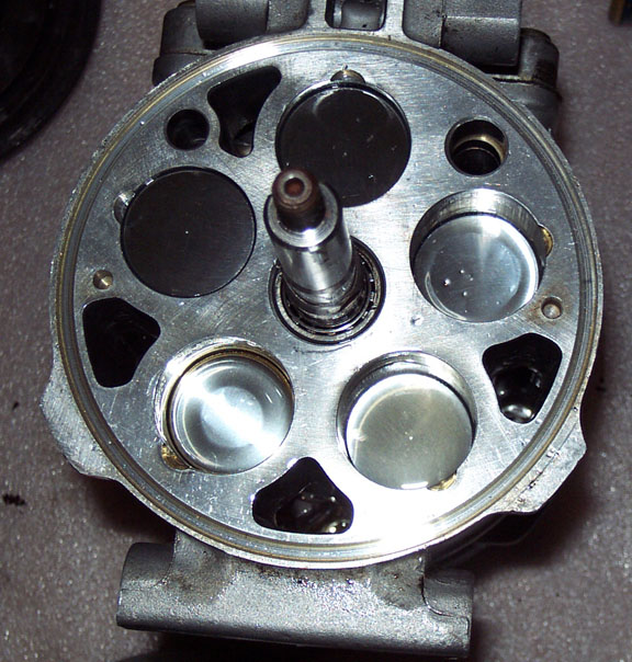
Picture 5 Pistons exposed with front compressor section off
4. The front piece of the compressor with the "nose" is where the shaft seal
is located. Look inside the nose,
find the felt seal and its brass retainer and remove them. They are to
be reused. Remove the circlip from
inside the nose. You do have a replacement for this so don’t worry
about ruining it.
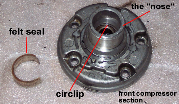
Picture 6 Front compressor section containing the shaft seal
5. From the inside (compressor side) of the nose drive out the seal and its retaining
ring with a 10mm or
11mm deep socket and a hammer. Go carefully so that the seal and ring
don’t "cock" in the housing.
You will destroy the old seal - when you see pieces of carbon
don’t worry about it. The retaining ring
is held in place with a friction fit using an o-ring. It may help you
to remove the seal if you lubricate the
nose with some of your refrigerant oil. The seal itself sits loosely
inside the shaft housing (nose); it’s not
pressed against the sides. Once the seal is out, clean the shaft
housing so that you don’t have bits of
carbon in there.
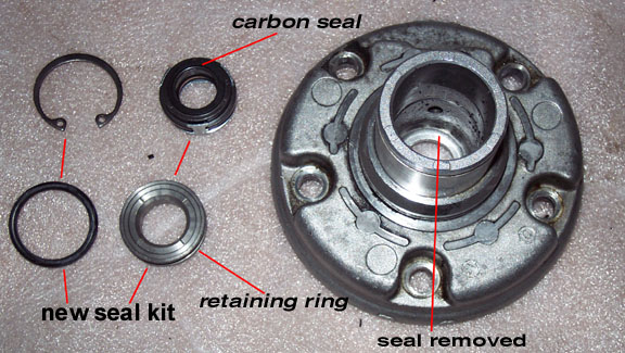
Picture 7 New seal kit, old seal removed
6. Install the new seal. The spring-loaded carbon assembly drops in first, the carbon
facing out and the
spring toward the rest of the compressor. You should avoid touching the
carbon itself. Now, you may
notice that the retaining ring is different than the one you removed.
One side of the new ring has a flat
surface - put the retainer in with this flat surface facing the carbon
seal after lubricating the new o-ring
with refrigerant oil. Now here I made a judgement call. The new
retainer will not take up the whole space
between the seal and the circlip that you removed . I drove the
retainer (with a 13mm deep socket) to
a point just below the groove for the circlip. If you study the
assembly, the actual seal is formed by the
carbon piece pressed against the retainer’s flat surface and the
circlip just prevents the pieces from
working their way out along the shaft. When you place the compressor
nose back on the compressor
the seal will be spring loaded against the retainer creating the seal.
I suppose that you could drive the
retainer all the way to the seal but I chose not to.
7. Install the new circlip in its groove.
8. Allow as much of the old refrigerant oil to drip out of the compressor as you can and
put 2 oz.
(Porsche's spec) of new oil in the compressor. Where you add it
doesn’t matter - it just circulates
throughout and is carried by the refrigerant around the system.
Just be certain that none of the cylinders
are completely dry. If you are concerned, rotate the compressor
by hand a few times after reassembly
to lubricate it.
9. If you are not resealing the case you are finished and can begin reassembly. When
replacing the
compressor nose piece be careful to avoid nicking the carbon - just put
the shaft through the seal as
straight as you can.
10. If you do reseal the case simply separate the sections, replace the large o-rings and
put it back together.
All of the components are constructed in such a way that proper
reassembly is made obvious with pin
locations and non-symmetrical parts. Also replace the four
o-rings at the hose fittings. Hint: separate
the two large case sections, replace that o-ring (lubricate with
refrigerant oil), replace the four hose
fitting o-rings, put the fittings back on and only then remove
the rearmost case section to replace its
o-ring. This will make sure that the pistons and wobble plate
don’t wander out of the compressor
while you are working. They are a royal PITA to put back
together.
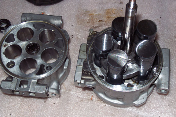
Picture 8 Main case halves separated
11. Using the new washers, reinstall the five compressor head bolts. If not yet
reinstalled, replace the hose
fittings.
12. Replace the clutch assembly. Make certain that you reinstall the spacers between the
pulley and the
clutch drive plate.
13. Remount the compressor, hook up the clutch wire and reattach the hoses, lubricating
(and replacing,
if necessary) the hose o-rings.
14. Take the car to an A/C shop and have it refilled. To be secure and happy you may want
the technician
to put a leak detector near the compressor shaft to check
your work.
15. You’re done!
If you use this article to rebuild your compressor and find that I’ve forgotten
something or have been unclear,
please e-mail me with feedback. Good luck!
Rod Walter
PCA Lincoln Trail Region
rwalter@winco.net