Intro
First we start with the obligatory joke: Electrical theory by Lucas--manufacturer of "quality" electrical systems for fine British automobiles.
The Lucas Theory of electricity: Electricity is actually Magic Smoke. This is obvious, because when you let the Magic Smoke out of the electrical parts, they don't work any more! The battery is a box with lots of Magic Smoke in it, and the smoke is used to power everything on the car. It takes a lot of Magic Smoke to run the starter, which is why the cable from the battery to the starter is so big. (There are about a million other Lucas jokes--in many places--to choose from, if you don't like that one!!)
Then again, the 914 has a Bosch-designed electrical system. So
perhaps I should describe how electricity works for the rest of us.
Volts, Amps, Ohms
You can think of electricity as a fluid, like the water in the pipes in your house. It flows from one place to another, and along the way it can do things for you. It always flows from a source to a ground (as long as you ignore some of the complexities about what is "really happening", where phrases like "the flow of holes" abound). This path of flow is called a "circuit", because the source and the ground are often close to each other. In an automobile, in fact, both are contained in one box--the battery.
There are three interrelated numbers that can be used to describe the electricity in some part of any given circuit. The first number is Voltage.
If you think back to our plumbing analogy, you can think of Voltage as being analagous to the pressure of the water in the pipes. Actually, it is a pressure differential between two parts of a circuit. Voltage is always measured from one spot in a circuit to another spot in that same circuit. You are said to be measuring the voltage "across" that part of the circuit. The units of this measurement are, unsurprisingly, Volts.
The next number describing the electricity in a circuit is the Current. In our plumbing analogy, current would be the flow of water through a particular section of pipe. You are said to be measuring current through that one spot in the circuit. The units of this measurement are Amperes, also known as Amps. (Sometimes current is called "amperage" because of this, but that usage is considered a bit sloppy.)
The third number of interest in the circuit is Resistance. In the plumbing analogy, this would be a restriction in the plumbing that water cannot flow through easily. You measure the resistance from one part of a circuit to another. The units for this measure are Ohms, also represented by the Greek letter Omega. Sometimes resistance is called "Impedance", though this is uncommon. It is even called "Ohmage" at times, but that is incorrect and a little bit silly.
These three quantities are related together by Ohm's Law--formulated by the same guy the resistance units are named for. This law consists of a simple equation:
V = I x R
That is, the voltage across a part of a circuit is equal to the current
flowing through that part of the circuit times the resistance through that
part of the circuit. The "I" above stands for current; I'm not sure
why it isn't an "A"... Regardless, the equation means that for a
given voltage, as the resistance in a part of a circuit goes down, the
current flowing through it goes up. Likewise, as the resistance in
a part of a circuit goes up, the current flowing through it goes down.
Measuring these Quantities
You measure one or more of these quantities to find out what is "going on" in some part of an electric circuit. You measure these quantities with a multi-meter, sometimes known as a Volt-Ohm-Amp meter. One example of multi-meter can be seen in Fig. 1. This is a relatively expensive Fluke meter, but even the $20 meters you can buy at Radio Shack and other electronics stores are good enough for most automotive work.
To measure the voltage across a part of a circuit, you set your multi-meter to "Volts" and the appropriate range (almost always the 20V range when working on cars), and plug in the probes to "common" and "Volt/Ohm" on the meter (see Fig. 2). Then you put one probe at one side of whatever you are measuring across, and the other probe on the other side. Make sure the ends of the probe are touching something conductive.
To measure the current flowing through one spot in a circuit, you set your multi-meter to "Amps" and the appropriate range (which can vary a whole lot, so start with the maximum range). Plug the probes in to "common" and "Amp" (see Fig. 3)--if you leave them in "Volt/Ohm" you can burn out the meter!! Then you break the circuit at the point you wish to take the measurement--e.g., you unplug a wire connector. You hook one end of the broken circuit to one probe of the meter, and the other end of the broken circuit to the other probe. Again, make sure that the probes are touching the conductive parts of the broken circuit. Note that all of the current in that circuit is now flowing through the meter, so if you are trying to measure very high currents you may burn out your meter anyway...
To measure the resistance of some part of a circuit, you set your multi-meter
to "Ohms". Plug the probes into "common" and "Volt/Ohm" (see Fig.
2 again). Then put one probe onto one end of what you are measuring
the resistance of, and the other probe on the other end of what you are
measuring. It is best to make sure that no electricity is flowing
through the circuit already, and that there is no other way for power to
get from the one probe to the other. So is is often the best policy
to break the circuit on one side or the other of the part that you are
measuring. Again, this can be done by un-plugging a connector.
Gauges and Senders
One of the "nice things" that we do with electricity in the 914 is that we use it to run gauges. A good number of the gauges in the 914 use Ohm's law.
Most of the electrical gauges in the car use the current flowing through part of the gauge to run an electromagnet. The magnet pulls on something connected to the needle of the gauge, which pulls against a spring that is trying to push the needle to zero. The more current flows through the electromagnet, the stronger the magnet's pull on the needle--and the further the needle deflects.
The oil temperature gauge works this way. It puts out a constant voltage on the "signal" wire that is connected to the temperature sender. The sender is a thermistor, a resistor that changes its resistance with temperature. In fact, it is a Negative Temperature Coefficient (NTC) thermistor--its resistance goes down when the temperature goes up, and goes up as temperature goes down. Ohm's law tells us that the sender, when cold, will let less current flow through it than it does when it is warm. (Remember, the voltage remains constant.) The current flowing through the sender is the same as the current flowing through the electromagnet in the gauge, so a cold sender will produce less magnetic force in the magnet, and so less deflection of the needle. A warm sender is low resistance, so it lets more current flow through it and through the electromagnet. The result is the needle in the gauge moves more.
The fuel gauge works in a similar way. The difference is that its sender is not a thermistor, it is a component that changes resistance as a float inside the fuel tank slides up and down. A lower float level will produce a higher resistance in the sender, so less current will flow through the magnet and the needle will move less. A higher float level will produce a lower resistance in the sender, so more current will flow and the needle will move more. (Yes, there is electricity flowing inside your fuel tank. That's not a problem--it is sparks that are a problem, and sparks require high voltage and a gap.)
The low-fuel warning light works in a slightly different way. The light is supplied with current when the ignition is on. The ground path for the light goes through the sender in the fuel tank. When the sender is low enough in the tank, a metal contact on the bottom connects the wire from the bulb to a ground. This completes the circuit, electricity flows through the bulb, and the light comes on.
The oil pressure warning light works in a similar fashion. However,
the sender in this case uses a spring-loaded plunger. The spring
pushes this plunger so that the wire plugged into it gets connected to
ground. This lets the current flow and the light comes on.
The oil presses against the plunger, and when it presses hard enough to
overcome the spring pressure (at about 5 PSI), the contact is broken and
electricity can no longer flow--so the light goes out. The sender,
in this case, works a lot like a switch.
Relays
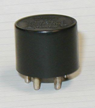
There are more switches than that in the 914, of course. Some of them look like Fig. 4--you're probably familiar with them if you've done much poking around your car.
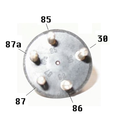
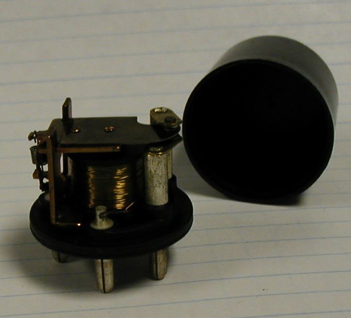
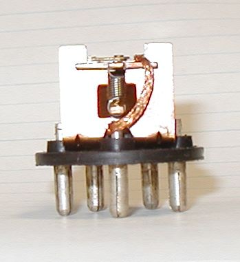
This is a relay. A relay is an electrically-operated switch. You'll notice the five pins on the bottom (Fig. 5). Two of them, labeled 85 and 86, are the ends of the coil of an electromagnet. When current flows through that coil, the magnet is turned on, and it pulls the switch inside the relay closed. The switch is spring-loaded, so that when the current does not flow, the switch is pulled open. Actually, on this particular style of relay, the spring holds the switch so that the #30 pin is connected to the #87a pin. When the relay is pulled closed (when current flows through the coil of the magnet), the #30 pin is connected to the #87 pin. Sometimes you can pull the plastic cover off of the relay, such as in Fig. 6. You can see a schematic diagram of the insides of a relay in Fig 7, which is from the relay board diagram from the factory and Haynes manuals. (Also available on our site.)
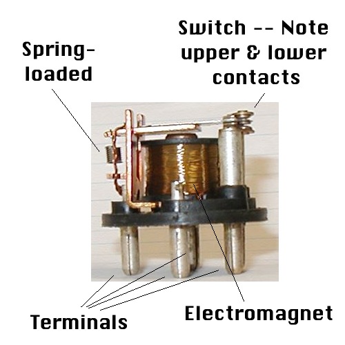
If you look at Fig. 8, you can see the coils of the electromagnet, the large copper mass in the middle. You can see the contacts of the switch at the upper-right. In Fig. 9, you can see the spring that pulls the switch part open.
Relays are used to "isolate" particular circuits. When something requires a lot of current to operate, and you don't want to have all of that current go through a switch, you can use the switch to send power through the coil of a relay. That lets you connect power directly from the battery to whatever requires lots of current--the switch is merely passing enough current to work the relay.
One example is the heater blower in the engine bay. It takes a
lot of current to run the blower motor. In this setup (and in most
places in the 914 where the round relays are used), pin #87a doesn't get
hooked to anything. The output, pin #87, gets hooked to the blower
motor. Pin #30 gets hooked to the battery (by way of a fuse).
Pin #85 is hooked up to something that has power when the ignition switch
is on, and pin #86 is hooked up to the switch on the heater control lever
in the cockpit. When the switch on the heater control lever is closed,
the wire to it gets shorted to ground. This completes a circuit through
pins #85 and #86 of the relay, which pulls the relay closed and connects
#30 to #87. Current flows from the battery, through the relay, to
the blower motor--and the fan runs.
Tracing Wiring Diagrams
The first thing most of us think when we look at a wiring diagram (like this one) is, "I see the spaghetti; where's the sauce?" Hopefully I can give you some pointers on how to trace the circuits. Note that Haynes has black & white repros of the color factory wiring diagrams. The fine print can be easier to read on them than it is on the JPEG diagrams on the Pelican site.
Some generalities: I think of circuits as being made up of "components", which are the parts that "do interesting stuff" for us, and "wires" which run between components. The wires are assumed to have a negligible resistance. This is a simplification which makes tracing the diagrams easier, but it isn't actually quite true--wires do have some resistance. The smaller the wire, and the longer the run of wire, the more resistance it will have. Long wires that need to pass a lot of current need to be very thick--which explains the big honkin' wire from the battery to the starter, the starter needs a whole lot of current and the wire is not very short. Note that all wires which are connected directly together (i.e., crimped into the same connector) are electrically "the same", they will always be at the same voltage.
You can think of the battery as something that always tries to maintain a constant 12V, and will put out whatever current it has to in order to keep its output at 12V. (Again, this is a simplification, but it is close enough for our purposes here.) In this view, the alternator is simply a "pump" that re-fills the battery with electricity.
Wiring colors tend to be pretty consistent on the 914. Brown,
you will notice, is always connected to ground. Solid red is usually
power, and is connected either directly to the battery, or possibly through
the ignition switch and maybe a relay as well. Ditto solid black.
Terminal numbers on the various components tend to be fairly consistent
as well--in fact (a web page exists) which mentions some of the Bosch numbering
conventions.
Tracing the 70-73 Wiring Diagram
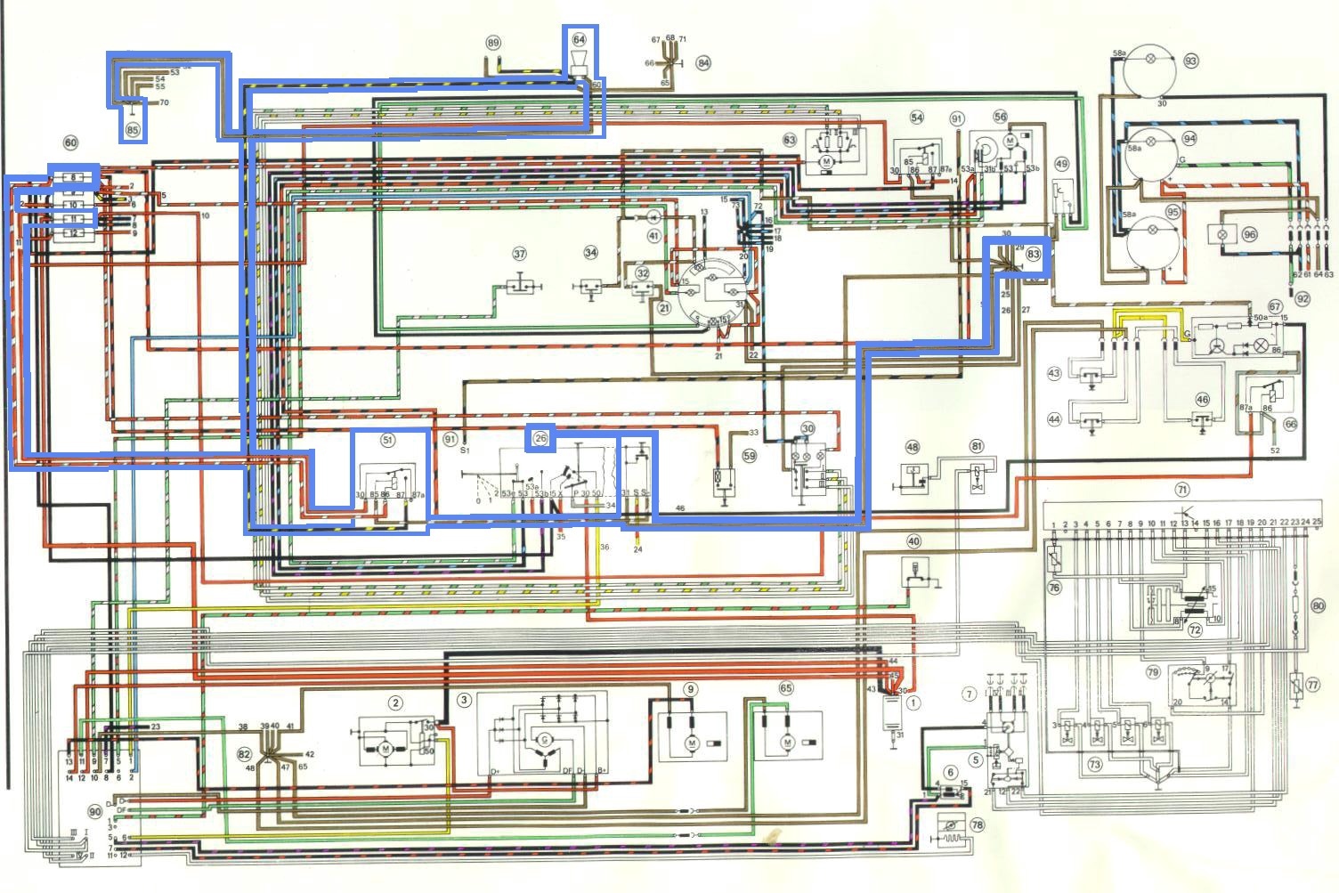
OK, now let's start tracing one circuit on Part 1 of the 1973 914 wiring diagram (Fig. 10). I will trace out the horn circuit verbally here, and you can follow on the diagram--I have highlighted the relevant wires to help you out, but obviously that won't help if you're looking at some other circuit... Now, the horn (look on the legend and you'll see it is listed as component 64) is something that makes noise when current goes through it. There is a little icon up at the top of the page that is labeled "64", and it even sort-of looks like a horn. (That's a bonus, they don't always look like what you think they should.) The horn icon is located at the top of the page because the actual horn is at the front of the car--if the horn were in the rear bumper, the icon would have been at the bottom of the page. If you look at the brown line on the right side of the horn, you can see that it goes over to the upper-left corner to #85, which is a ground point. Assume that this ground point is equivalent to the battery ground post; so you've found one end of this circuit.
The wire on the other side of the horn (black with a yellow stripe) runs down to component 51. This is listed on the legend as the Horn Relay. Note that it is connected to pin #87 of the relay, which as we've already seen is the "output" of the relay. So we have to figure out what it is that gets connected to #87 when the relay is triggered, and also what triggers the relay. We can trace the wire back from #30 to fuse #11 on the fuse panel. You can either take my word that fuse #11 is connected directly to the battery (+) terminal, or you can flip to (Part 1 of the diagram) and see that another wire runs from the left-hand side of fuse 11 to the battery. This wire is connected to the same connector as the wire to #30 of our relay, so you can think of it as being the same as connected to the battery. (Note that power can go from the battery to the relay without going through the fuse--not the greatest idea...) Anyway, we seem to have figured out that pin #30 is always "hot", so when the relay is triggered it will let current flow to the horn. Current will flow through the horn, and the horn will make noise. (With me so far??)
Next we have to figure out what triggers the relay. Terminal #86 is connected to a red-with-white-stripe wire that goes to the left-hand side of fuse #8. Fuse #8 is fed by another relay (component #54) which feeds power to fuse #8 when the ignition key is turned to "on". You can either take my word for that too, or trace the circuitry out for yourself. Anyway, if you can believe me then terminal #86 of the horn relay is connected to power whenever the ignition key is "on".
So that leaves terminal #85 on the horn relay. This has a brown and yellow wire that goes over to component #26, which is called "Steering column switch" in the diagram legend. It connects to terminal "S" on this component. Now if you look up above that connection, you can see little lines inside the switch. Note the small black circle, and the line going across to the black circle on the next line. This is actually showing you a switch which can connect those two circuits together. So when this switch is closed, our wire gets connected to the part of the switch that runs to terminal 31 on the switch. A brown wire connects to this terminal, and the brown wire runs to #83, which is the ground up behind the dashboard. So we've found what happens to terminal #85 on our relay. When a switch is closed, terminal #85 gets connected to ground.
So, what happens is that when the ignition key is on, #86 gets power from the battery. When a switch is closed, #85 is connected to ground. Current flows through the electromagnet of the relay, and the relay is triggered and so #30 gets connected to #87. #30 is connected to the battery, and #87 is connected to the horn. Current flows to the horn, and since the other end of the horn is connected to ground, current flows through the horn. "BEEP!"
Note that there are a few places here and there you will see wires ending
with nothing connected to them except a small number. Those are a
challenge... What that generally means is that this wire is continued
on the other page of the diagram. So if you look at the tach icon
(#22) on Part 1 of the 73 diagram, you'll see three wires coming off the
bottom of it that run to little numbers, 22, 21, and 23. To trace
those, you have to turn to Part 2 and look for those numbers. 21
and 22 connect to the bottom of the combo gauge (component #21), and I
still
can't find where 23 goes...
Tracing the 74+ WiringDiagram
The later diagrams are called "current flow diagrams" and they are laid out differently than the early ones. In these, current almost always comes into the circuit up at the top, and ground is always at the bottom. Circuits are laid out according to their functions, not necessarily according to their location in the car. I like my boss Wayne's description of these as "waterfall diagrams", where the water comes in at the top and falls through all the bits down to the bottom--that is in general the flow of current. It can be a bit of a pain locating some components, but I prefer the later diagrams because I feel it is easier to trace the circuits on them.
On the 1975 wiring diagram (Fig. 11), I will trace out the oil temperature gauge circuit. Note that the oil temp gauge has a light in it that comes on when the headlights or parking lights are on; that is a separate circuit and is not part of this description. Now if you look in the legend for the 75 diagram (on Page 6 of the diagram), the oil temp gauge is listed as "G9 - Oil Temperature Indicator", and is listed as being on track 54. Track 54 is on Page 4 the way we split up the diagram originally. (If you're following along in Haynes, note that Pages 1, 2, and 3 are Part 1; Pages 4 and 5 are Part 2.) Looking up from the "54" at the bottom of the page, you will find "Y", "G14", and "G9". Note the circle-with-arrow icon which looks a bit like a gauge.
The bottom connection of the gauge is hooked to a red-with-white-stripe wire. This wire goes through a connector (labeled "T1a"), and joins with two more wires, one grey-with-brown-stripe and one black-with-yellow-stripe. The latter wire goes up to "S9", which is fuse #9 on the fuse panel. The other side of fuse S9 is connected to the ignition switch ("D"), and any time the key is not "off" that wire (terminal #15 on the switch) is connected to terminal #30 on the switch. Note the small line across the top of the switch; that means a connection inside the component. Terminal #30 goes directly to the battery, component "A". So we know one connector on the gauge has power any time the ignition is on, and that the power comes through the ignition switch and goes through a fuse.
The other end of the gauge is connected to a green-with-black-stripe wire. This wire goes through another connector ("T1a"), and connects to G8, which the legend tells us is the "Oil temperature sender unit". The icon is a little block with an arrow, which means "resistor that can change resistance". The other end of this component is connected by a thin line directly down to the ground--which means that this component is grounded directly, not through a wire. In the case of the temp sender, it screws into a plate that is attached to the crankcase with a metal-to-metal contact, so it is screwed into a ground. So we know that the other end of the gauge connects to the sender, which itself is grounded.
We now have our circuit, and if you think back to the "Gauge theory"
section above, you can see how this gauge works.
Other Things to Think About
Hopefully you now have a general idea of how to read an electrical diagram, and some idea of what some of the components in the car actually do and how they work. With luck, you now have enough tools and information that you can start trying to figure out what is actually going on with the help of your multi-meter and your wiring diagrams.
There are a lot more things to consider, before you start tearing into the wiring of your car.
First on the list are fuses. Fuses are a Very Good Thing. They are things that don't have significant resistance, but can only cope with a certain amount of current flowing through them. After that level is reached, they melt down and don't conduct anything any more. When this happens, when the fuse "blows" or "pops", this means that some part of the circuit that is "downstream" of that fuse has shorted to ground. This can happen when a connector becomes disconnected and flops onto the chassis, or when the insulation on a wire fails, or someone gets too near the wire with sheet-metal screws, or... Fuses are very important, because without them all the current from a short circuit (remember, V = I x R; a short circuit has just about zero resistance so the current gets very large) goes through a component, or just through the wires. Enough current will "fry" a component or a wire. At best, the wire acts as a fuse and you have to find a way to replace one wire in the wiring harness. At worst, the wire heats up to the point where things around it catch fire. Not good.... So you can see how it is important to have fuses--and to have them sized appropriately so that they will pop before the wires burn up.
Next on the list are connections in general, and grounds in particular. I mentioned above that we assume wires don't have any resistance, because it makes tracing the diagrams simpler. It is true enough for appropriately-sized wires in good condition, but very much not true for connections that are dirty. Not only do dirty connections have some resistance, but their resistance can change depending on external factors like heat. So you can get some very strange effects when you have dirty connections in a circuit. So it is almost always a good idea to clean up every connection you can reasonably get to--or at least every connection you find yourself messing with anyway. Electronic stores sell "Contact cleaner" (Radio Shack calls theirs "TV Tuner Cleaner", Wuerth calls theirs "Contact OL") which you can spray onto the metal contacts of a connection. It is not a bad idea to plug and un-plug the connection a couple of times to rub the metal parts of the connection together to try scrubbing off dirt. And finally, an eraser that is intended for ink--the one with grit in it--can also be useful if you can get to the metal parts that actually make contact. Grounds are often exposed to the elements and are often not very well protected, so they are extra likely to need some cleaning. If you can keep dirt and water (most especially water!) out of the connection, you should be able to keep it cleaner. Dielectric grease can come in handy for that. But more importantly is cleaning up the metal at the connection--a wire brush can be your friend here! And since 914s do tend to rust, you ought to know that rusty metal does not conduct very well. So any ground point that is rusty and doesn't have a "clean" path to solid metal is very suspect, and you should consider moving it.
Third on the list are mixed-up connections. I often lump this in with "grounds" above, but it is only partly related. When power and grounds get mixed up, sometimes you get very unpredictable results. Sometimes, if you're lucky, you simply pop a fuse. If you're unlucky, there are extra components in between the fuse and the mis-wire, so there is no immediate obvious result. Not only do things get mis-connected from people unplugging things and plugging them in wrong, but even putting the wrong light bulb in can have that effect.
My story: One of my brake lights went out. I replaced the
bulb (a dual-filament bulb, though I didn't realize it) with a single-filament
bulb. It turns out that you can make the single-filament bulb
fit in the dual-filament socket, but the power and ground are in different
spots. So one of the power connections is actually connected directly
to the other one. Nothing bad happened immediately, but the car started
behaving very oddly. The strangest behavior was that the engine would
stay running even after I turned the key off--but only if the left turn
signal was on!! When I installed the correct brake light bulb, all
the weird problems went away. I finally figured out that the left
"parking light" function (where part of one taillight stays lit with the
ignition off when the turn signal is on) was feeding power back through
the brake light circuit into the ignition switch, and enough power was
going through it to actually let the engine continue to run. Very
very strange...
More Sources
Let me conclude with a few more sources of electrical troubleshooting
information for you.
Jim Thorusen has written some very thorough articles for Pelican's
web site. If you are having any problems with these systems, you
can't do better than start with his troubleshooting procedures.
Ignition System Troubleshooting: http://www.pelicanparts.com/techarticles/914_ignition_troubleshoot/914_ignition_troubleshoot.htm
Charging System Troubleshooting: http://www.pelicanparts.com/techarticles/914_alternator_troubleshoot/914_alternator_troubleshoot.htm
Starting System Troubleshooting: http://www.pelicanparts.com/techarticles/mult_starter_diag/mult_starter_diag.htm
Headlamp Motor Troubleshooting: http://www.pelicanparts.com/techarticles/914_headlamp_motor/914_headlamp_motor.htm
Fluke Autotools has a whole lot of info about using their tools to troubleshoot
various things on your car. A surprising amount of things can be
checked with a simple Volt/Ohm meter. A small-capacity Ammeter can
check a bunch more.
http://www.fluke.com/application_notes/automotive/beatbook.asp?AGID=1&SID=103
Brad Anders has posted a wealth of information on his Rennlist Member
web site. Among other things, he has dissected the headlight switch
and figured out what makes it tick:
http://members.rennlist.com/pbanders/headlight_switch_internals.htm
He has put together a troubleshooting flow-chart for the fuel pump
control system on D-jet (stock 1.7, 2.0) cars:
http://members.rennlist.com/pbanders/FPChecklist.htm
And he has gathered together as much D-jet EFI info as I have seen
anywhere:
http://members.rennlist.com/pbanders/DJetParts.htm
There are a lot more sources out there, I am just listing the ones that occurred to me first. Good luck!!